Simultaneous recording of front view with Full HD resolution
(1920x1080, 25fps) and rear view with HD resolution (1280x720,
25fps) provides super high quality videos.
USER MANUAL
www.blacksys.co.kr/en
02
Notice
Notice
This product helps you to use the recorded video as a reference in case of car accident. The recorded video by this product carries no legal binding force.
CammSys will not be responsible for any legal conict and damage caused by recorded or non-recorded video.
• For safety, do not operate this product while driving such action may result in injury or accident.
• An accident at very low speed or impact may not trigger emergency recording and could be recorded as a normal file.
• Recording may not be executed in case the product is defect caused by car accident or other reason.
• Recording can be distorted under the condition where brightness suddenly changes like passing through a tunnel,
direct sunlight reflection during the day time or where light is not available at night time.
• All right to hardware, software and relevant data are reserved by CammSys Corp. and protected under copyright law.
In case of illegal copy and process, not only civil compensation but also criminal punishment based on protection of intellectual property
rights can be engaged.
• Do not use the product for other purpose rather than Car DVR.
• In case of recording other’s voice without permission, you will be liable for legal responsibility.
(In case that you save other person’s voice without any permission, be cautious that you may have legal liability)
• CammSys will not be held responsible for any damage caused by negligence, careless and improper management of user.
• Cammsys do not ensure that record all the accidents in case of not operating 3D G-Sensor with subtle impact.
• Cammsys will not be held responsible for any loss caused by malfunctions or loss of recorded image from external influences or accidents.
03
Table of contents
Table of contents
02
Notice
04Caution
04 … Installation and Maintenance
06 … SD Card Use
06 … Use of Power
07 … OBD Management
08Main features
13Components
13 … Standard Components
14 … Front
14 … Rear
15 … Upper Side
15 … Right Side
16 … Components of OBD Device
17 … OBD product specification
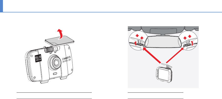
18Installation Method
18 … Front Camera Installation
42… Screen saver
43… Initialization
44… SD card format
45PC Viewer instructions
45 … Software installation & uninstallation
46 … PC Viewer Layout
47 … Basic use
48 … Configuration
50Firmware Update
51How to format SD card
52Technical Specification
53Customer Service
54Warranty
55Product Warranty
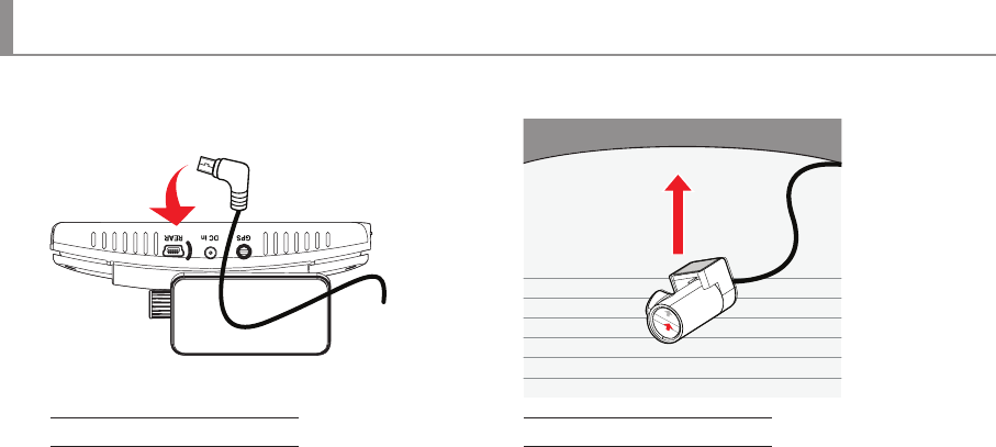
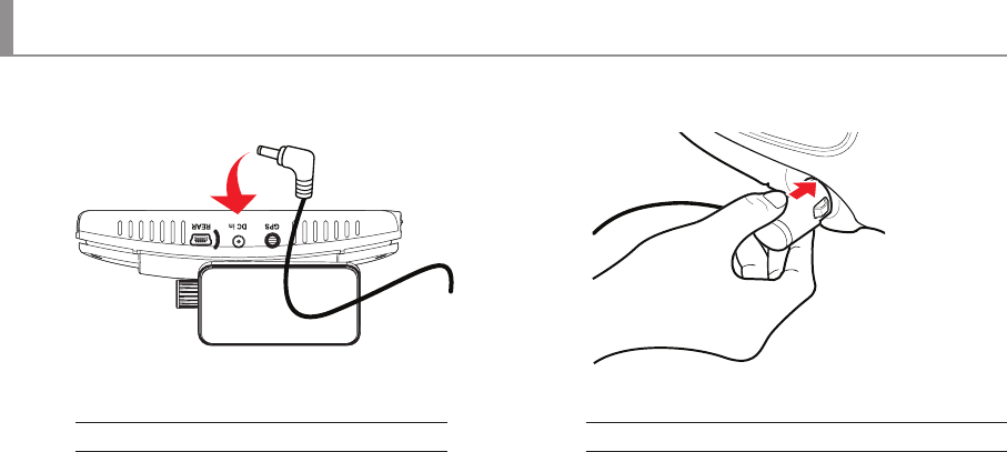
19 … Rear Camera Installation
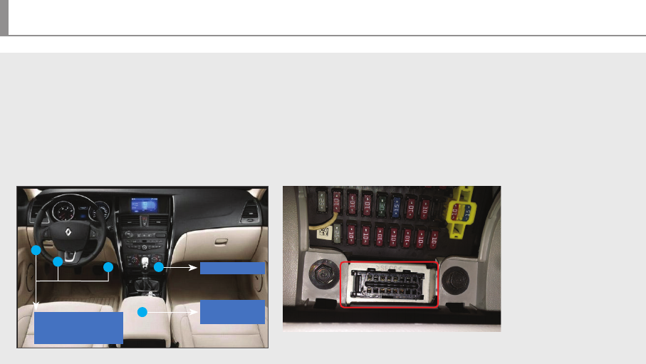
21 … OBD Terminal Installation
24Operating device & instructions
24 … Details on Video Record
25 … LED indicator and Voice guide
27LCD GUI
27… LCD preview screen instruction
28… LCD main menu
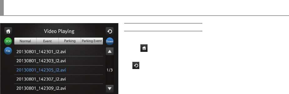
30… Video recording
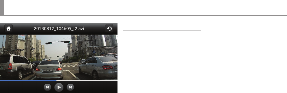
31… Video Playing
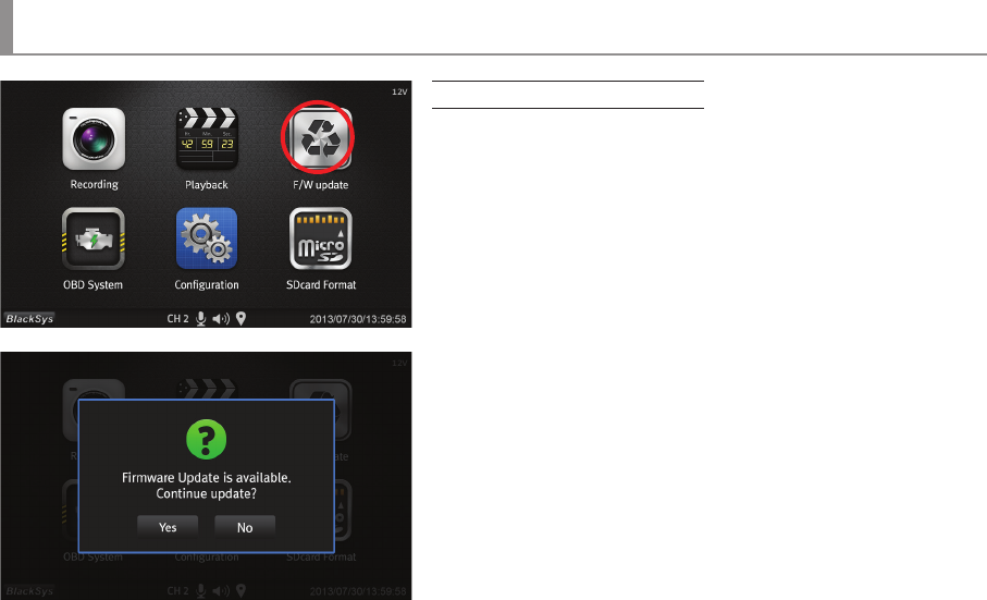
33… Firmware Update
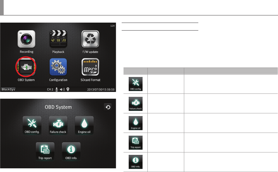
34… OBD main
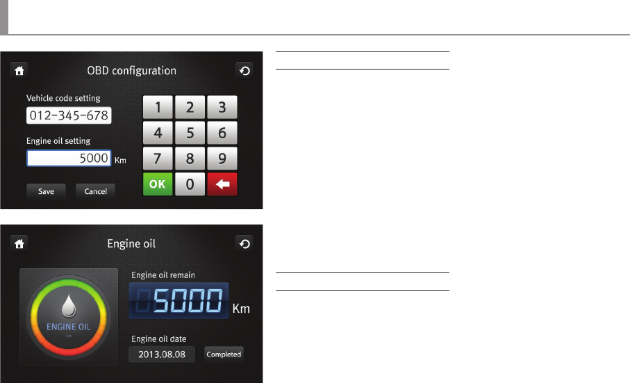
35… Setup and engine oil information screen
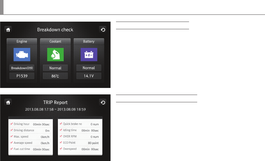
36… Screen for Malfunction Diagnosis & Trip Report
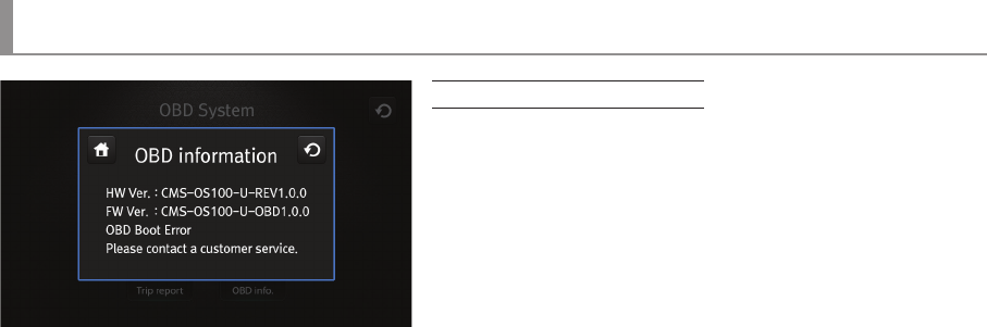
37… OBD Information
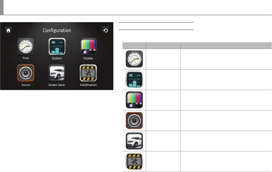
38… Configuration main menu
39… Time & System Setup
40… Display
41… Sound
04
Caution
Caution
Before use the product, check if operation and video recording goes well.
Installation and Product Management
• Keep the camera lens clean by preventing dust or foreign substance from coming into contact with the lens. Otherwise, this may result in video
distortion. So keep the area clear around the installed camera. If another object is placed around, it can be reflected from the window.
So do not put another object around the installed product.
• If installation location of the product is changed, it may not record properly even if it worked after initial installation.
Therefore, install the product firmly and do not give an excessive shock or force to move the product.
• Continuous removal of the bracket from the windshield may cause weakening of the adhesive strength
and new adhesive pads should be used to prevent damage. Please be cautious when install the product.
• Please check the position of SD card before inserting.
• In the case of using the power from the vehicle
(DC fused power), please disconnect the power cable if you do not use the product for a long time.
(It may cause discharge the battery.)
• Do not switch power off while firmware is upgrading. It may cause malfunctioning.
• Long term use of this product or in case of severe vibration may cause change in angle or location of product.
Correct the angle or location of product while stop on a flat location.
05
Caution
Caution
• Do not use chemicals or detergents to clean the product. This can result in a malfunction.
• Never cause excessive shock to or inject a foreign substance into the product.
Causing excessive force or shock or injecting a foreign substance into this product can cause malfunction.
• Avoid high temperature (direct sunlight) or high humidity for normal operation of product. If it has to be parked for a long period in summer,
we recommend that park in the shadow or indoor.
• Do not disassemble or repair this product. It can cause malfunction and such action will result in the product being void of all warranty
/service provisions.
• Do not use a sharp object on the LCD screen or touch screen. It may cause of screen damage.
• If power is supplied constantly, it may damage the vehicle battery efficiency. So it is recommended that raise the cut-off voltage.
(If it has to be parked for long hours, power cable should be separated.)
• Electric connection should be made either at cigar jack power or OBD power, but not both at the same time.
When electric connection is made both at cigar jack power and OBD power at the same time, it would damage the OBD module.
• Be cautious when connecting OBD cable with rear camera terminal to avoid product damage.
06
Caution
Caution
SD Card Use
Be sure to turn OFF the power and the LED is OFF before removing or inserting the SD card. Removing the SD card while product is in use can cause a malfunction.
• Use the authorized SD card which the manufacturer/distributor provided. If unauthorized SD cards are used, it may cause malfunctioning and loss
of recorded data.
• Do not disassemble or repair this product. It can cause malfunctioning and will void warrantee.
• SD card is an expendable supply. After a period of use, it may not able to record data correctly. Please change the SD card to a new one.
Data can be lost and damaged if data is kept in SD card for a long time.
• If you want to keep the videos, back up the data onto other storage devices such as HDD, CD and USB. Keeping the data in SD the card only,
may cause data loss and damage.
• Check the recorded data of SD card regularly to make sure that recording is working well
• Recommend to format SD card at least once in 15 days for stable operation.
• As SD card is expendable supply, manufacturer is not responsible for any data loss and damage caused by not using for a long time.
Cammsys will not be held responsible for it
Use of Power
• This product is designed to be plugged into a cigar jack power only. In the case of using any other power source from the vehicle,
consult with your local vehicle dealer. Please note this method is outside of manufacturer’s responsibility under any circumstances
and cannot be held liable for damage or injury.
• Do not remove or insert SD card while power is turned on, it can cause serious error of the product.
Make sure to turn OFF the power and LED is OFF before removing or inserting the SD card. Removing the SD card while product is
in use can cause damage of video file.
07
Caution
Caution
OBD Management
• In case of any vehicle malfunctions when connecting OBD, separate device immediately and call Customer Service Center.
It can be caused by product defect or careless mounting.
• OBD will operate to detect motion in parking mode even if it turns off ignition.
Decrepit car battery can be cause of discharge. So recommend do disconnect power cable or replace to new battery.
• Installation of OBD may cause some confliction messages between auto care services and car diagnosis on Hyundai/Kia car original navigation
functions. This is due to the duplication of car diagnosis. Please try to follow the installation manual.
• Please check the model supporting list before install the product.
There are some vehicles that are not supported and some features not supported models.
• Model supporting list and functions are updating consecutively, so please check through our website or Customer Service Center.
• Do not remodel OBD or amputate cable. It can bring vehicle damage and the user has responsibility for any loss.
• Installing OBD may differ from the type of vehicle, so recommend to install at professional vehicle shop.
Installation at discretion may cause the damage.
• Average fuel efficiency can vary with actual fuel expenses, and our product does not assure this. Use only for reference.
• Eco-Driving information may different depending on the vehicle and individual.
• Driving distance and speed information may differ from dashboard due to the vehicle manufacturer self-calibration.
• Diagnostics of vehicle diagnose errors of Engine sensor (ECU) which is controlled electronically.
Does not diagnose mechanical failure (puncture of tire, expendables, external damage)
• In terms of vehicle maintenance, its point of view can vary, please use it for reference only.
08
Main features
Main features
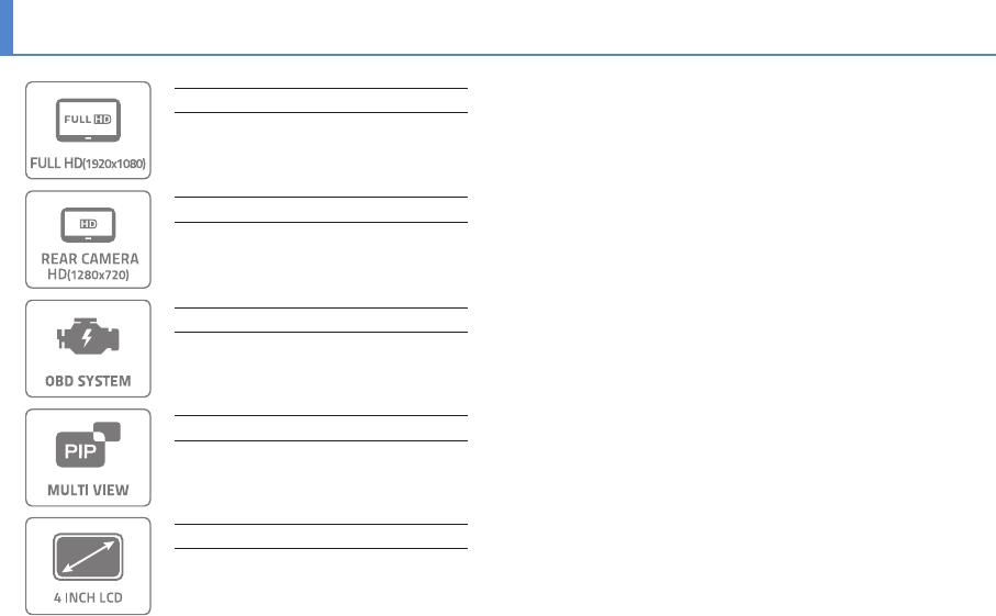
Full HD resolution for high quality video
F1.8 Lens with Sony Exmor sensor provides brighter and clear high quality Full HD images.
High quality HD rear camera recording
720P HD resolution with 25fps
4.0 inch wide viewing angle LCD
With the wide screen of 4.0 inch Full Touch High Denition LCD, it is possible to set the menu and check images.
OBD SYSTEM (Optional)
It is possible to check the information about the accident situation, malfunction diagnosis, eco-driving, automotive service
information in real time. So it is possible to make an accurate decision in regarding of accidents and support the maintenance
of a vehicle.
PIP Multi Viewer Function
It is possible to divide a screen as the front screen and the rear screen upon recording and they could be watched concurrently.
Also, it is possible to move the screen.
09
Main features
Main features
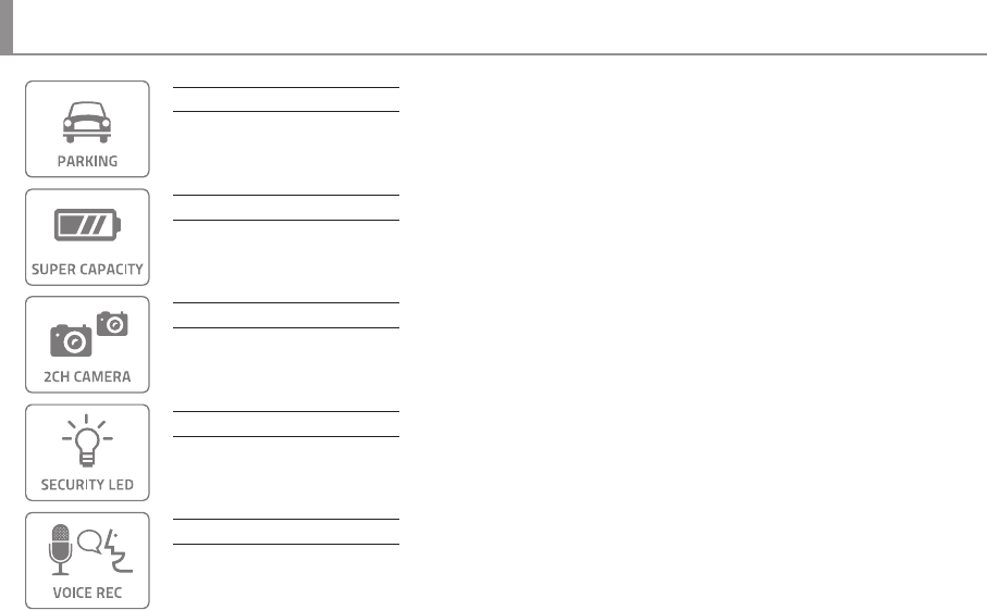
Parking Mode Recording
Parking mode activates automatically when vehicle stops for a certain amount of time if DC fuse power cable is connected
and any damage of vehicle can be recorded.
Super Capacity (Backup Battery)
Built-in super capacity secures safe storage of recorded data even when power supply is disconnected caused by unexpected
accident or impact.
Front and Rear recording
Front with Full HD, Rear with HD resolution at 25 fps respectively.
LED Lighting
Security LED in front indicates that Car DVR is installed in this vehicle and it is always operating while Car DVR is powered on.
Rear LED with blue color indicates state of each function such as recording and GPS reception.
Voice Guide/Recording
Voice guide announces each action and state. Built-in microphone records voice and surround sound which helps situation
analysis in case of accident.
10
Main features
Main features
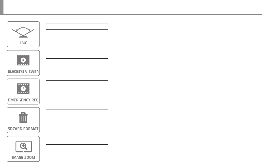
130° Angle of View
130° Diagonal angle lens can record wider angle of view.
Dedicated PC viewer
BlackSys PC viewer provides not only video playback and but also video analysis.
Emergency Button Recording
User can record event manually with emergency button during driving, parking and accident. Recording total 30 sec. including
10 sec. before and 20 sec. after from the time of pressing emergency button is performed. The recorded video at the moment is
stored in event folder
Manual Format
Manual format is available without PC.
Zoom function using PC viewer
Zoom-in the important points of video through PC viewer.
11
Main features
Main features
Location and driving information (Optional GPS)
Optional high-sensitive GPS(SiRF 4) records vehicle speed, route and location information. It is synchronized with Google Map
and displays the driving path. It is easy to trace back to the location of the accident using Blacksys PC Viewer.
Video Out (Optional Cable)
If DC fuse power cable is connected, recording is available during parking mode.
Normal Recording
All the images in the driving are recorded continuously as 1 minute le.
If memory is full, recording starts overwriting from the oldest le by deleting them in order.
Motion Detection in Parking Mode
When motion is detected during parking or stopping, recording get started for a certain time and if motion is not detected,
recording is put on standby without recording. This mode stores only necessary videos, SD card memory is managed eciently.
3D G-Sensor
3-axis G-Sensor detects impact, brake, acceleration of vehicle and automatically records video images. To avoid overwriting,
it stores les in a separated folder.
12
Main features
Main features
Real-time check and indication of vehicle voltage / Low voltage protection
Since it is possible to check voltage patterns of a vehicle in real time, a user can set up voltage to be suitable for a situation as
well as battery discharge prevention method.
High Temperature Prevention Function
It is a system of which shuts o the black box automatically if the main unit device reaches the temperature which can be strain
to the system and then turns on the black box when temperature decreases to a safe level.
13
Components
Components
Actual components may be dierent from pictures and some components can be changed in case.
If package doesn’t include below components, please contact a retail shop or company where product was sold.
Standard Components
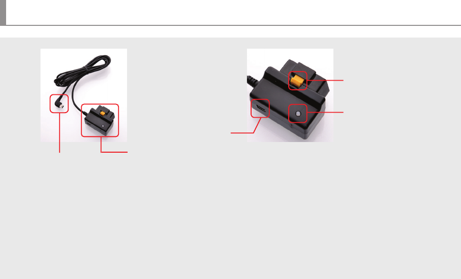
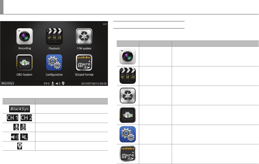
Main Unit (Device)User ManualCable HolderMicro SD Memory
Cigar Jack Cable
(Excluded if OBD is selected)
Option
External GPS modul
OBD terminal
DC Fuse Power Cable
Rear CameraHolder
U
S
E
R
G
U
I
D
E
14
Front & Rear
Components
Speaker
Action state, Voice guide
Emergency Recording Button
For manual Recording
Camera lens
For video recording
Parking Mode LED
LED indicator for parking or
video recording
Holder
Attach the Car DVR to the front window
15
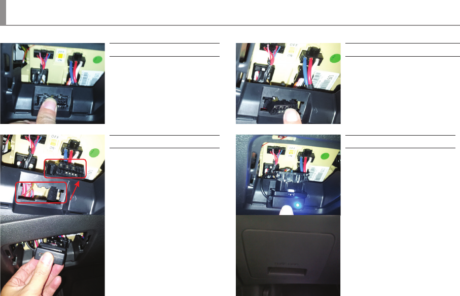
Up & Right side
OBD Connection Terminal
Check driving information by
connecting OBD cables
OBD LED
Connecting status indicator
Power Terminal
For supplying power
to the main unit using
cigar jack
Clamping lever
For xing holder to product
and adjustment available on
up/down, left/right side
Rear Camera connection port
Mini USB port for HD Rear Camera
Micro SD card slot
External Micro SD card port
REAR LED
Connecting status indicator
REC LED
Recording status indicator
GPS Port
For checking location and
speed of vehicle through
dedicated PC viewer
① GND
② GPS Data
③ Power
Components
OBD
REAR
GPS
REC
OBD
GPS LED
Connecting status indicator
16
Components of OBD Device
Components of OBD Device(※OBD Optional Components)
• Black Box Connection Jack : Connection jack which connect with function of OBD terminal (CarNSys) and permanent power.
• Fixed device : A device for fixing a vehicle OBD terminal and an OBD terminal (CarNSys) main device.
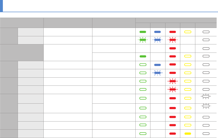
• Operation Status LED :
- Blue lighting : Vehicle identification and normal operation status - Blue blinking : Unidentified vehicle
- Red blinking : Defective terminal - Pink blinking : Detection of vehicle malfunction
• Terminal for connecting PCs : Currently disabled
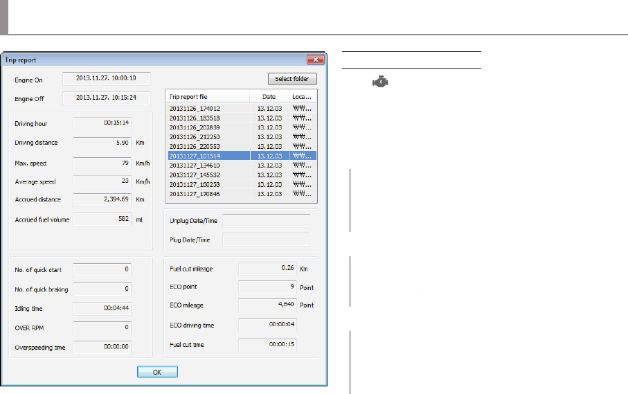
- Fuel cut millage : Accumulated distance in inertia driving
caused by discontinuance of fuel supply
- ECO point : ECO driving score based on report value
- ECO millage: ECO driving accumulated score
- Eco driving time : No. of hours in economic driving
- Fuel cut time : Hours in inertia driving caused by discontinuance of fuel
PC Viewer instructions
50
Firmware Update
Firmware Update
Firmware Update
Please follow the below process in case of updating rmware.
① Remove SD card from the unit.
• Turn off the ignition first and remove cigar jack cable from the unit.
② Access our webpage(www.blacksys.co.kr > Support > Download) and download the latest update file.
③ Connect SD card to PC and paste downloaded latest update file(CF100update.tar) to the root of removable disk.
④ Insert SD card which contains latest update file to the unit.
• Turn on the ignition and connect cigar jack cable to the unit.
⑤ Touch the LCD screen and enter a main menu mode, and then click a firmware update button to upgrade.
• Do not disconnect power cable while update is in process. It can cause malfunctioning.
※ Please check notice before upgrading firmware as firmware upgrade may change some functions of the product.
51
How to format SD card
How to format SD card
PC format
① Insert or connect SD card to PC.
② Click [Start]→[My Computer]
③ Place mouse pointer on[Portable USB drive]SD card and click the right button of mouse. then click the[Format].
④ Once click the[Start]button, format is started.
• FAT 32 format is required if SD card recognition and record error happen.
• Change SD card if PC doesn’t recognize SD card or format is not able to be completed.
• If SD card contains other data, it can cause malfunctioning. Therefore, please remove it.
※ As SD card is expendable supply, manufacturer is not responsible for any data loss and damage. Also, manufacturer cannot guarantee the recorded data in SD card.
Check the virus and format the SD card in a regular basis (twice a month at least) to avoid disadvantage caused by storage error such as non-recording and abnormal recording.
52
Technical Specication
Technical Specication
※ Technical Specication can be changed without prior notice for product improvement..
Model NameCL-100B
Camera
Lens (Pixel)Front : 2M Pixels, Rear: 1M Pixels
Angle of ViewFront : 130° / Rear: 120°
Sensitivity (Intensity of Illumination)1.0 LUX
Function
Video Encoding / Voice EncodingH.264(AVI) / PCM
ResolutionFront : 1920(H)x1080(V) Full HD, Rear : 1280(H)x720(V) HD
Normal RecordingNORMAL (70% of memory space, 1min./le, 30 frame/s)
Recording Options
EVENT (20% of memory space, 30sec./le, 30 frame/s)
Auto Parking Mode (1min./le, 30frame/s)
Rec. Method (Video Recording)In case SD Card is full, it deletes the oldest les (automatically) in order
Voice RecordingBuilt-in MIC records voice and surround sound
If you come to customer service center, service personnel will care for the service timely and properly.
For further information regarding customer service, please refer to www.blacksys.co.kr/en.
54
Warranty
Warranty
We provide product repair and replacement services within the warranty period
in accordance with the consumer protection regulations(the Korea Fair Trade Commission Directive 2008-3)
Warranty period
•Product(main unit): 12 months from the purchase date(But, if purchase date is not clear, it can be applying 3 months warranty after manufacturing date)
• Accessory(expendable supply) : 6 months including SD card.(In case of using DC fuse power cable, memory card life can be shorter than general use)
• Service parts holding period: 5 years after stopping sales
※Warranty period is 12 months after purchase.
※We provide product repair and replacement services within the warranty period in accordance with the consumer protection regulations.
(the Korea Fair Trade Commission Directive 2008-3)
Claim a service for trouble
caused in a normal use
condition
Type of Damage
Compensation standard
Within Warranty PeriodAfter Warranty Period
Claim a service for a main part within 10 days after purchaseReplacement or refundNot applicable
Claim a service for a main part within 1 month after purchaseReplacement or Free repairNot applicable
Claim a service for faulty unitFree repairRepair at cost
Repair is not availableReplacement or refundReplacement or refund after depreciation
Replacement is not available Refund at costApplicable by bylaw
Claim a service for a main part within 1 month after unit exchangeRefund at costApplicable by bylaw
Same defect over 3 timesReplacement or refundNot applicable
Multi defect over 5 timesReplacement or refundNot applicable
Lost by service center during repair serviceReplacement or refundApplicable by by law
Claim a service for not
holding service parts within
service parts holding period
Trouble caused in a normal use conditionReplacement or refund
Not applicable
Customer’s negligence or fault, functional defectRepair at cost
Damaged unit from distribution ReplacementNot applicable
Damaged unit from installation ReplacementNot applicable
Customer’s negligence or
fault, Functional defect
Repair is availableReplacement at costApplicable by bylaw
Repair is not availableRepair at costRepair at cost
55
Product Warranty
Product Warranty
※ The warranty for the product is beneted by the details on the warranty card.
※ Warranty period is counted from the purchase date. So get the purchase date.
※ This warranty card is not reproduced.
Model NameCL-100B
ManufacturerCammsys Co.,Ltd
Serial No.
Purchase Date
Warranty Period12 months from the purchase date
(But, if purchase date is not clear, it can be applying 3 months after manufacturing date)
Customer Information
NameTel.
Address
Assembler informationShop nameTel.
Daeil Bldg 3F, 681-17, Yeoksam-dong, Gangnam-gu, Seoul, Korea
Gebruikershandleiding.com neemt misbruik van zijn services uitermate serieus. U kunt hieronder aangeven waarom deze vraag ongepast is. Wij controleren de vraag en zonodig wordt deze verwijderd.
Product:
Spelregels forum
Om tot zinvolle vragen te komen hanteren wij de volgende spelregels:
lees eerst de handleiding door;
controleer of uw vraag al eerder door iemand anders is gesteld;
probeer uw vraag zo duidelijk mogelijk te stellen;
heeft u een probleem en al geprobeerd om dit op te lossen, vermeld dit erbij aub;
heeft u een oplossing gekregen van een bezoeker dan horen wij dat graag in dit forum;
wilt u een reactie geven op een vraag of antwoord, gebruik dan niet dit formulier maar klik op de knop 'reageer op deze vraag';
uw vraag wordt direct op de website gezet; vermijd daarom persoonlijke gegevens in te vullen;
Belangrijk! Als er een antwoord wordt gegeven op uw vraag, dan is het voor de gever van het antwoord nuttig om te weten als u er wel (of niet) mee geholpen bent! Wij vragen u dus ook te reageren op een antwoord.
Belangrijk! Antwoorden worden ook per e-mail naar abonnees gestuurd. Laat uw emailadres achter op deze site, zodat u op de hoogte blijft. U krijgt dan ook andere vragen en antwoorden te zien.
Abonneren
Abonneer u voor het ontvangen van emails voor uw Cammsys BLACKSYS CL-100B bij:
nieuwe vragen en antwoorden
nieuwe handleidingen
U ontvangt een email met instructies om u voor één of beide opties in te schrijven.
Ontvang uw handleiding per email
Vul uw emailadres in en ontvang de handleiding van Cammsys BLACKSYS CL-100B in de taal/talen: Engels als bijlage per email.
De handleiding is 6,74 mb groot.
U ontvangt de handleiding per email binnen enkele minuten. Als u geen email heeft ontvangen, dan heeft u waarschijnlijk een verkeerd emailadres ingevuld of is uw mailbox te vol. Daarnaast kan het zijn dat uw internetprovider een maximum heeft aan de grootte per email. Omdat hier een handleiding wordt meegestuurd, kan het voorkomen dat de email groter is dan toegestaan bij uw provider.
Stel vragen via chat aan uw handleiding
Stel uw vraag over deze PDF
Uw handleiding is per email verstuurd. Controleer uw email
Als u niet binnen een kwartier uw email met handleiding ontvangen heeft, kan het zijn dat u een verkeerd emailadres heeft ingevuld of dat uw emailprovider een maximum grootte per email heeft ingesteld die kleiner is dan de grootte van de handleiding.
Er is een email naar u verstuurd om uw inschrijving definitief te maken.
Controleer uw email en volg de aanwijzingen op om uw inschrijving definitief te maken
U heeft geen emailadres opgegeven
Als u de handleiding per email wilt ontvangen, vul dan een geldig emailadres in.
Uw vraag is op deze pagina toegevoegd
Wilt u een email ontvangen bij een antwoord en/of nieuwe vragen? Vul dan hier uw emailadres in.