Output Wiring...............................................................................................................................Designed for using four speakers only
RCA line out.....................................................................................................................................................low-level outputs - 1000MV
Output Impedance................................................................................................................................Compatible 4 to 8 Ohm Speakers
Dimensions.......................................................................................................................................128mm(W) x 125mm(D) x 100mm (H)
Weight.....................................................................................................................................................................................................2.8 Kg
TFT/SYSTEM
Resolution.....................................................................................................................................................................800RGB(H) X 480(V)
FM Sensitivity......................................................................................................................................................................................12dBu
AM Sensitivity......................................................................................................................................................................................30dBu
Specifications
8
BASIC OPERATION
1. Tuning the unit On / Off
Press the Power Button to turn the unit on. The opening screen of the unit will be showing on the TFT monitor. Press and hold the
POWER button again to turn the unit off.
2. Turning the TFT On / Off
During any play mode, press the Power Button once to turn the TFT screen off for screen saving and avoid distraction while driving. The
sound will continue to play. Press the Power Button again to turn the TFT screen back on.
3 HOME Button
In Radio and Aux modes, press the HOME button to go back to the home screen. You can select different play modes by turning and pressing the volume
knob. Also you can enter the setup menu in the home screen.
In USB and SD modes, during music or video playback, press the HOME button once to go back to the directory page, in which you can choose the desired
file by pressing and turning the volume knob. Press again the HOME button to go back to the home screen.
4. Wall Paper Selection
Tap the Wall button on the right bottom corner of the OSD. You will enter the wall paper selection screen. Select the image by tapping
on the image name then tap OK. The selected image will become the new wall paper on the OSD. You can put more images (BMP files:
720x480) in the map SD card (path: \data\wallpaper) for more selection.
5. Day Light Saving
Tap the Day button on the OSD to increase brightness. Tap again to reduce brightness during night time. Tap again for black out the screen.
9
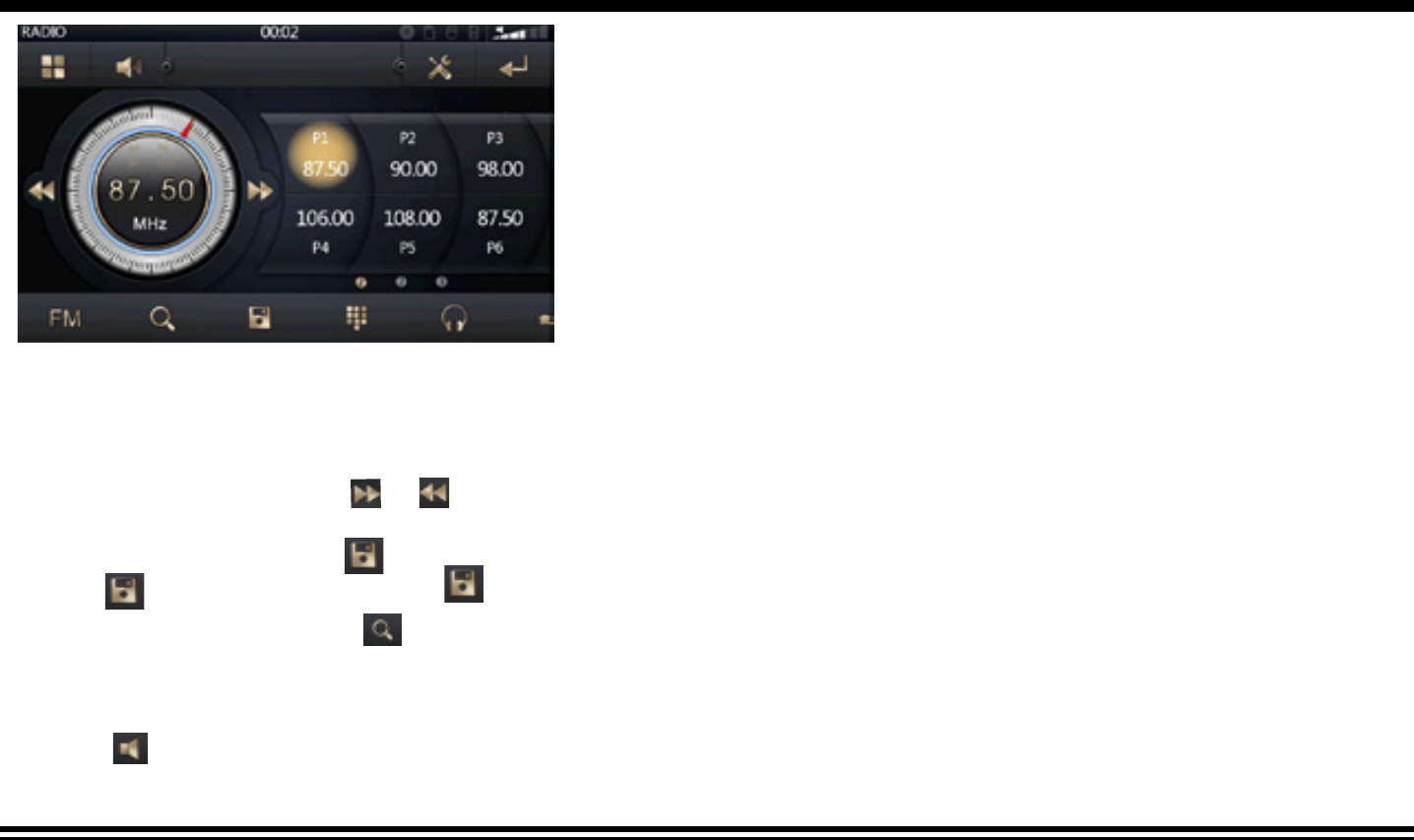
1. Choose Radio Band
Touch the AM button on screen to choose among the five radio bands - three FM Bands (FM1, FM2, and FM3) and two AM Bands (AM1,
and AM2). Each of the five bands can store up to six preset stations, for a total of 30 preset memory stations.
2. Radio Seek Function
In Radio Mode, touch and hold or Button to adjust the radio frequency automatically. Press the button once to adjust the radio
frequency manually.
3. Save Your Preset Stations
Press the button and then press the from P1 to P6 to save a preset station.
4. Automatic Store/Preset Scan
While listening to the FM Radio, touch and hold the AMS Button. The receiver will automatically scan and save stations for all the 3 FM
Bands, whichever band (FM1, 2 or 3) you are listening to. Touch the AMS button again to scan and listen to the stations you have saved.
Repeat the same steps for AM Bands.
5. Mute
Touch the mute button to mute the unit. Touch again to disable the mute.
Radio Operation
10
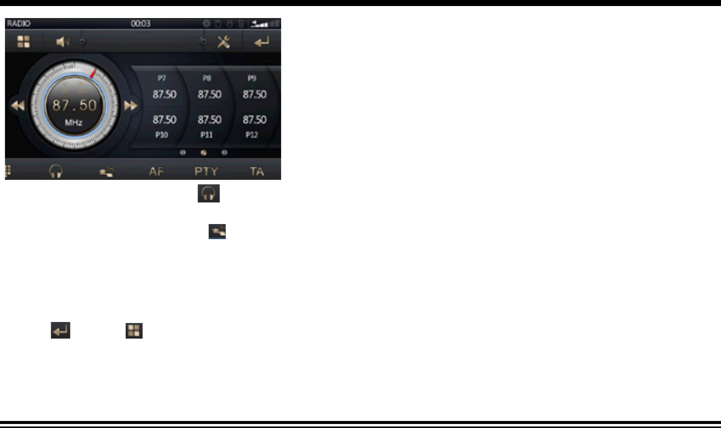
Radio Operation (Con’d)
6. Mono/Stereo Reception Control
In FM radio mode, touch the ST button to select stereo or mono reception.
7. Local/Distance Reception Control
In radio mode, touch the LOC button to select local or distance reception.
9. RDS Control (Optional)
AF, TA, PTY are the RDS functions. They are applicable to certain countries only. For countries when RDS is not available. The touch
sensitivity of the button will be disabled.
10. Returning to Main User Interface
Touch the button or button to return to the main user interface.
11
Bluetooth Operation
PAIRING
At BT mode, search bluetooth device by the phone and “RMN575BT Caliber” will appear in your phone. Input “0000” as password to
establish connection.
DIAL PAD
Touch the dial pad to dial the number you would like to call. Touch the CALL (green) button to send the number.
CONTACT
Press the CONTACT button to enter phone book function. Press the button to download the phone list. Press the button
to search the contact person. Press the button to delete the phone list.
CALL RECORD
Press the HISTORY button to enter the phone book page to view received, missed and dialed calls. More details in the next page.
A2DP
Press the MUSIC button to enter the A2DP page to control playing music of your cellphone. More details in the next page.
REJECT CALL
Press the REJECT (red) button to end the call or to reject an incoming call.
RETURN TO USER MANUAL
Touch the button or button to return to the main user interface.
12
Bluetooth Operation (Con’d)
View Received Calls
Touch the RECEIVED CALLS button, the received calls will be displayed.
View Missed Calls
Touch the MISSED CALLS button, the missed calls will be displayed.
View Dialed Calls
Touch the DIALED CALLS button, the dialed calls will be displayed.
Playing Music on your cellphone
After activating music player in the cellphone and it will play automatically, touch to play or pause the music. Touch and
to select uo or down one song in your song list.
13
Plug the USB device into the USB port. The unit will play the contents automatically.
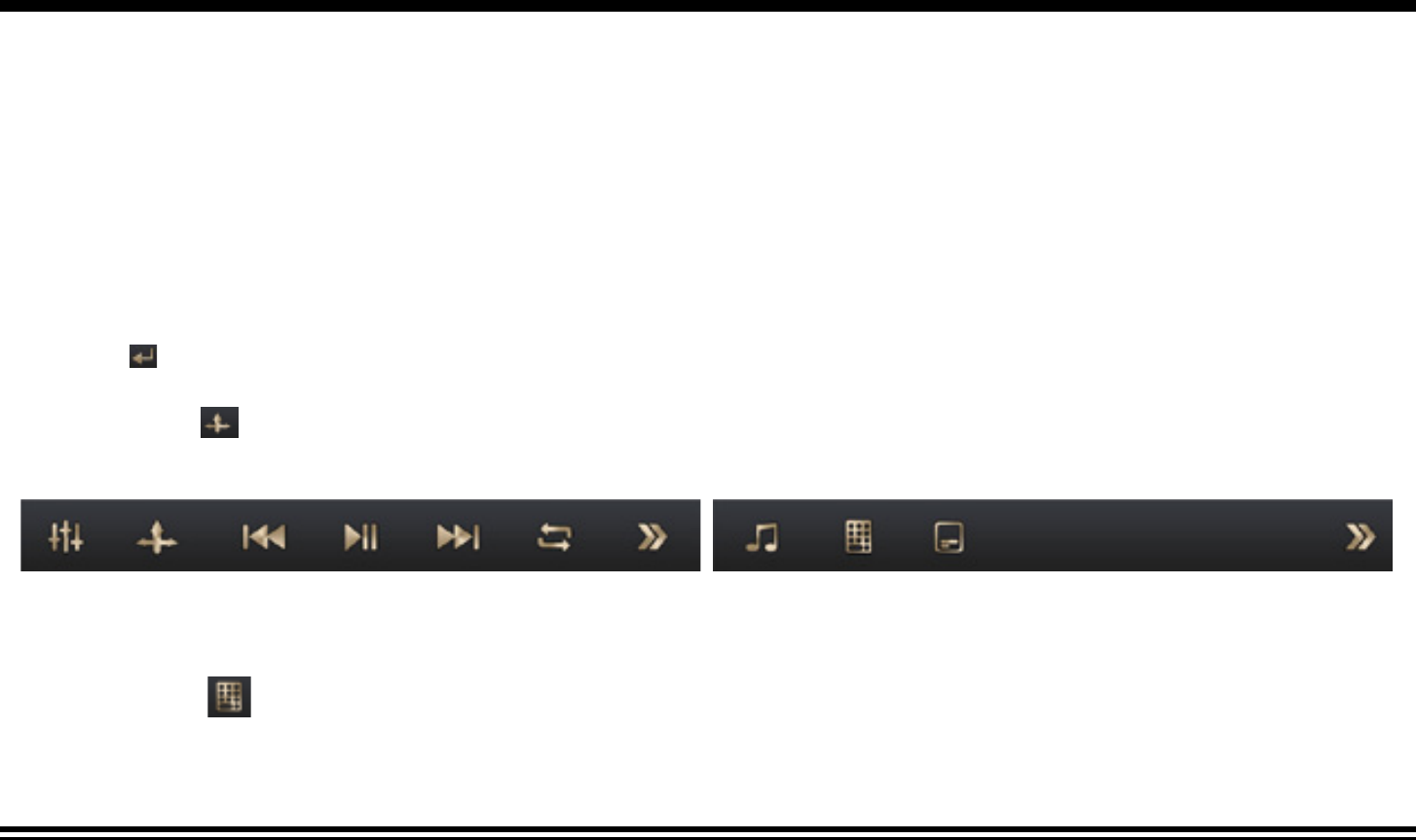
1. Advance / Go Back
Advance to the next track or go back to the previous track by pressing the forward or rewind buttons on the front panel or touch
screen.
2. Play/Pause
Press the play/pause button to pause the playback or resume.
3. Fast Forward/Fast Rewind
Press and drag the proceeding bar during media playback. The unit will fast forward/rewind the song/video until you release.
4.Directory page
Press the button during playback in order to see the full list of files along with file types. All the file names are displayed for your
easy reference. Select the desired file types and file names by tapping on the screen.
5. Aspect Ratio
During video playback, tap the screen in order to switch the aspect ratio of the video. On the menu you can select full screen, 16:9,
and 4:3 accordingly. The viewing effect will depend on the video file so it may vary.
Play
Pause
Track
Down
Track
Up
Repeat
Next
Page
Audio
Selection
RandomRatioEQSubtitle
6. Track Search
Press the GOTO button to search the desired track to play the Vedio. Press the ENTER button to confirm your selection.
USB Operation
14
7. Repeat Function
Press the Repeat button to toggle between repeat chapter, repeat single, repeat all and repeat off.
8. Subtitle Selection
Press the Sub-T button to choose the sub-title you want. The sub-title languages available differ from Disc to Disc. You can also
use the setup menu to confirm. Refer to the packing of the Disc for details.
9. Electronic Skip Protection
This unit is programmed with Electronic Shock Protection (ESP) so that the video will be protected against rough roads for 5
seconds.
10. Returning to Main User Interface
Press the button or button to return to the main user interface.
USB Operation
15
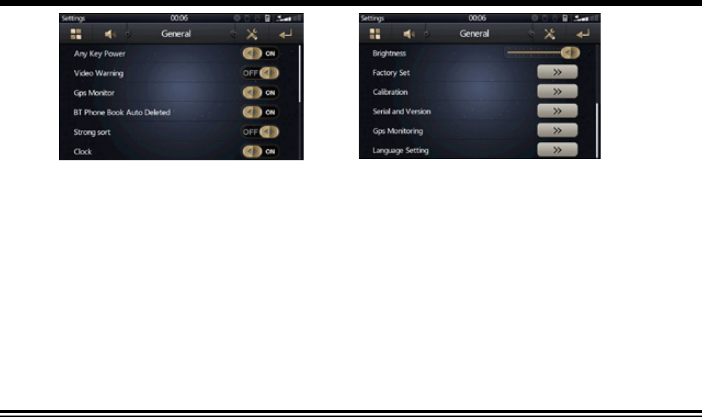
Settings
General Setting
The general setting menu includes any key power, video warning, GPS monitor, BT phone book auto deleted, strong sort, brightness,
Screen reguate, factory set, calibration, serial and version, GPS monitoring, language setting, reset factory.
16
Settings
EQ Setting
You may set EQ, touch sound, back car vol, user def vol, GPS
You can select Date, Time, Time mode and Time zone by
tapping directly on the options .
Tap after the setting to take effect.
17
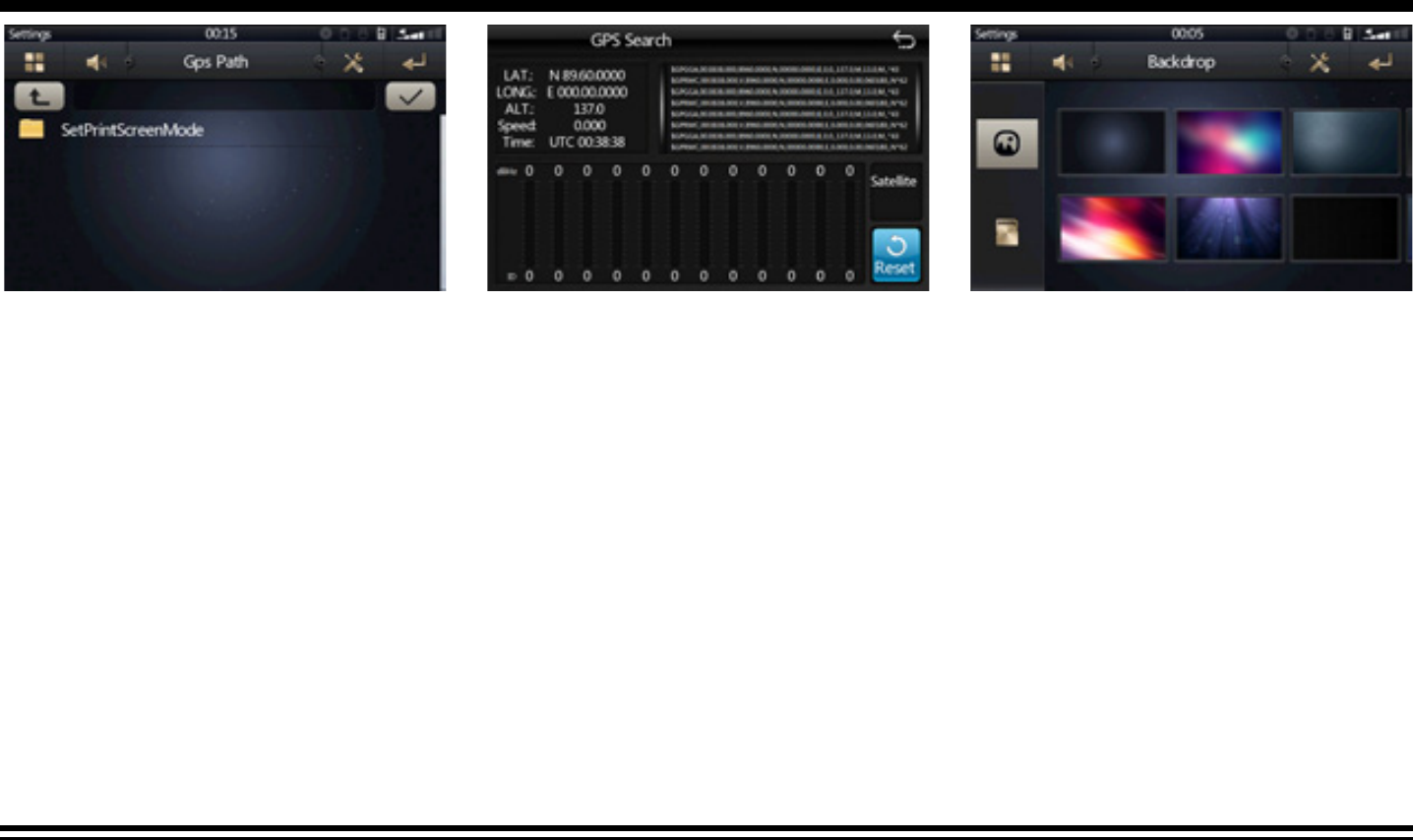
GPS Setting
Enter the GPS setting to define the link of the execution file
of your GPS program. Consult the installer if you are not
familiar with the setting. Tap OK after the full path is insert-
ed. Now you can enter the Navigation mode in the OSD.
Make sure you have inserted the GPS map card properly
(the lower micro SD card slot of the front panel) before the
settings.
Settings
Wall Paper Selection
Tap the Wall button on the right bottom corner of the OSD.
You will enter the wall paper selection screen. Select the
image by tapping on the image . The selected image will
become the new wall paper on the OSD. You can put more
images (BMP files: 720x480) in the map SD card (path: \
data\wallpaper) for more selection.
18
Steering Wheel Control (Optional)
Refer to the wiring diagram for connection. The brown wire (SWC 1) must be connected, then the white or grey (SWC 2A and 2B) will
be connected depending on the total number of the wire from the steering wheel remote control of your vehicle.
TAB STEERING WHEEL LOGO in the OSD. Press before the set up. Select from the 10 functions according to the number of
available keys on the steering wheel of your vehicle. Press any key on your steering wheel, then tab the function key you would
like to assign. The frequency of the function will be shown on the display. Repeat the step for other keys on the steering wheel. Tab
after your set up is complete and then you can operate the unit by your steering wheel.
19
Other Operations
1. GPS Navigation If GPS navigation is available with the system, Tap the GPS logo on the OSD to enter GPS navigation. Follow the on screen instruc-
tion to input destination and start navigation. The operation varies from software to software.
2. AV Input
The AV Input Jack is a set of composite input on the rear of the unit. Press the Mode button to choose AUX. Connect any portable audio/video device
such as a DVD player. Use the volume control to adjust volume.
3. Backup Camera Input
The backup camera input is on the back of the unit. (refer to wiring diagram). This input (in yellow) is for connecting backup camera for parking. You
must connect the VCC wire (in pink color) to the reverse gear switch in order to activate this video input mode when you switch the reverse gear of your
car. Please refer to the wiring diagram for more details.
4. Video Output
The Video Output Jack is on the back of the unit. (Refer to Wiring Diagram) This output (in yellow) is for connecting monitor(s). You must connect a moni
-
tor for car in order to play this unit in another monitor. Consult your dealer for any kinds of monitors that are suitable to use in car. Press the “BND/SYS
” button to choose between PAL and NTSC mode.
5. RCA Outputs
The RCA Output Jack is on the back of the unit. (Refer to Wiring Diagram) This output is for connecting amplifier, equalizer, or other audio component that
requires a pre-amp out connection. (Red=Right, White=Left) Follow the manufactures instructions for the audio component that you are connecting.
6. Subwoofer Output
The Subwoofer Output Jack is on the output wire harness. (Refer to Wiring Diagram) This output is for connecting up to 2 subwoofer amplifier to the
Subwoofer Output Jack to drive a subwoofer. Follow the amplifier’s installation instructions. Press and hold the BND/NP/SUB button to activate or
deactivate this function.
21
INFRA RED REMOTE CONTROL
1.Power on/off
2. Mode Select Key
3.Play / Pause Function
4.Mute Sound Function
5.Band Select
6/7/10/21.Cursor Button in Menu Mode
8.Confirm The Track/Chapter Selected
or Select Item In SETUP Menu
9. Stop Playback
11. Repeat Play Function
12.Program The Tracks To Be Played/Stereo Selection
13.Random Play Function
14/26. Track Up / Down or Fast Forward / Backward
15. PBC Play Mode
OSD
PBC
12
3
4
5
678
90
GOTO
10
VOL
A
UDIO
VOL
SELECT
ST
PROG
AMS
RPT
SEEK
LOC
RDM
SEEK
MUTE
SUB-T
ZOOM
SLOW
SETUP
ENTER
TITLE
MOD
BAND
ANGLE
1
2
3
4
5
6
7
8
9
10
11
12
13
14
15
16
17
18
19
20
21
22
23
24
25
26
27
28
29
30
16. Statistical Disc Information Display Button
17. Number Select Key
18.Subtitle Language Switching Key
19. Show All Track's Title (for DVD units only)
20. Display SETUP Menu
22. Play DVD in Slow Advance
23. Watch The DVD Content From Different Angle
24. Zoom In and Zoom Out Function
25/29. Adjust Volume Level
27. Sound Select Button
28. Change The Audio Output Method
30. Track Time Serach
22
SIMPLE TROUBLESHOOTING GUIDE
PROBLEMCAUSE / SOLUTION
No PowerCheck whether the fuse is blown, replace with fuse of proper value
if necessary.
Unit stops responding or shows errorPress the RESET button.
in display
Unable to receive radio stationsCheck whether the antenna is inserted or the antenna is properly
connected; if not, insert the antenna or connect it properly.
Poor effect on receiving a station-Antenna may not be of the proper length. Make sure the antenna is
fully extended. If broken, replace the antenna with a new one.
-The broadcasting signal is weak.
-The antenna is poorly grounded; check and make sure the antenna is
properly grounded at its mounting location.
Discs cannot be loadedDisc already loaded in the mechanism.
No pictures-The video line from main unit to monitor is not connected properly.
(for external monitor)
-The purple brake wire is not grounded or connected to brake properly.
The picture appears grainy-Check the color system. (PAL or NTSC)
Gebruikershandleiding.com neemt misbruik van zijn services uitermate serieus. U kunt hieronder aangeven waarom deze vraag ongepast is. Wij controleren de vraag en zonodig wordt deze verwijderd.
Product:
Spelregels forum
Om tot zinvolle vragen te komen hanteren wij de volgende spelregels:
lees eerst de handleiding door;
controleer of uw vraag al eerder door iemand anders is gesteld;
probeer uw vraag zo duidelijk mogelijk te stellen;
heeft u een probleem en al geprobeerd om dit op te lossen, vermeld dit erbij aub;
heeft u een oplossing gekregen van een bezoeker dan horen wij dat graag in dit forum;
wilt u een reactie geven op een vraag of antwoord, gebruik dan niet dit formulier maar klik op de knop 'reageer op deze vraag';
uw vraag wordt direct op de website gezet; vermijd daarom persoonlijke gegevens in te vullen;
Belangrijk! Als er een antwoord wordt gegeven op uw vraag, dan is het voor de gever van het antwoord nuttig om te weten als u er wel (of niet) mee geholpen bent! Wij vragen u dus ook te reageren op een antwoord.
Belangrijk! Antwoorden worden ook per e-mail naar abonnees gestuurd. Laat uw emailadres achter op deze site, zodat u op de hoogte blijft. U krijgt dan ook andere vragen en antwoorden te zien.
Abonneren
Abonneer u voor het ontvangen van emails voor uw Caliber RMN801BT NAVI bij:
nieuwe vragen en antwoorden
nieuwe handleidingen
U ontvangt een email met instructies om u voor één of beide opties in te schrijven.
Ontvang uw handleiding per email
Vul uw emailadres in en ontvang de handleiding van Caliber RMN801BT NAVI in de taal/talen: Engels als bijlage per email.
De handleiding is 2,59 mb groot.
U ontvangt de handleiding per email binnen enkele minuten. Als u geen email heeft ontvangen, dan heeft u waarschijnlijk een verkeerd emailadres ingevuld of is uw mailbox te vol. Daarnaast kan het zijn dat uw internetprovider een maximum heeft aan de grootte per email. Omdat hier een handleiding wordt meegestuurd, kan het voorkomen dat de email groter is dan toegestaan bij uw provider.
Uw handleiding is per email verstuurd. Controleer uw email
Als u niet binnen een kwartier uw email met handleiding ontvangen heeft, kan het zijn dat u een verkeerd emailadres heeft ingevuld of dat uw emailprovider een maximum grootte per email heeft ingesteld die kleiner is dan de grootte van de handleiding.
Er is een email naar u verstuurd om uw inschrijving definitief te maken.
Controleer uw email en volg de aanwijzingen op om uw inschrijving definitief te maken
U heeft geen emailadres opgegeven
Als u de handleiding per email wilt ontvangen, vul dan een geldig emailadres in.
Uw vraag is op deze pagina toegevoegd
Wilt u een email ontvangen bij een antwoord en/of nieuwe vragen? Vul dan hier uw emailadres in.