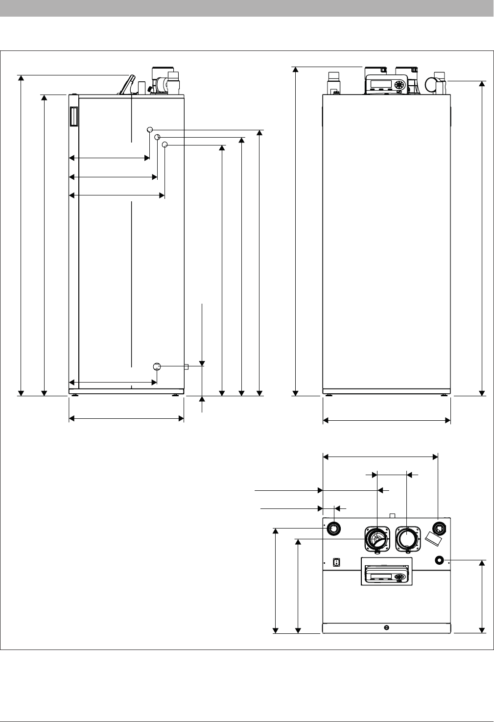
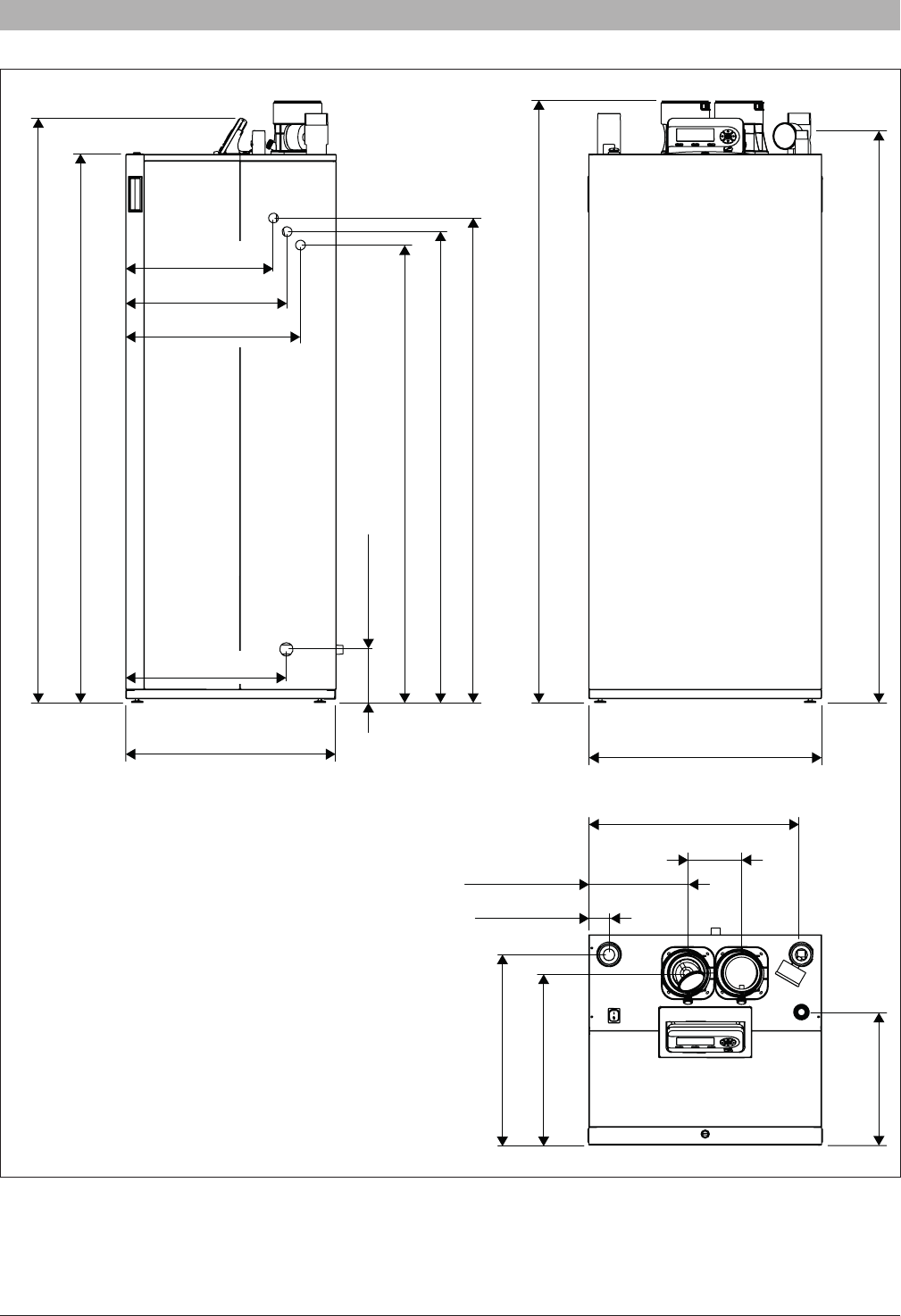
Min. clearance to combustibles ***Inch (mm)2” (50.8)2” (50.8)2” (50.8)
Dimension WxHxD
Inch
(mm)
23 31/32” x 61 9/16” x 21 21/32”
(609x1564x550)
23 31/32” x 61 9/16” x 21 21/32”
(609x1564x550)
23 31/32” x 61 9/16” x 21 21/32”
(609x1564x550)
AHRI certied ratings
UnitSSB255SSB399SSB512
InputMBH255399511.8
Heating CapacityMBH237.0n/an/a
Gross OutputMBHn/a386.0495.0
AFUE%96n/an/a
Combustion Efciency%n/a97.695.4
Thermal efciency%n/a96.996.8
Net ratingMBH206.0336.0430.0
CO
2%10.210.19.5
(*) With conversion.
(**) FLA (Full Load Amperage) - maximum current drawn by the boiler without pumps.
(***) The 2” minimum clearance is required for all sides of the boiler. The boiler may be installed on combustible (wood) oors excluding carpets.
See Fig. 9 for minimum clearance recommendation for serviceability.
SSB6720818454 (2016/02) US
Product description | 11
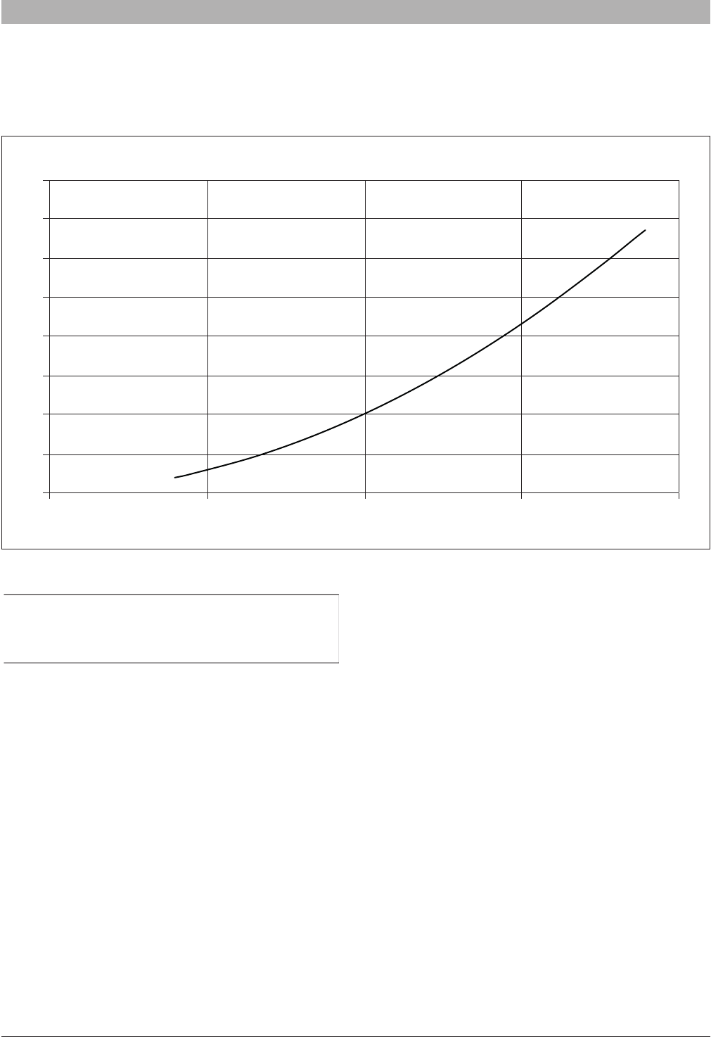
2.8 Efciency Curves
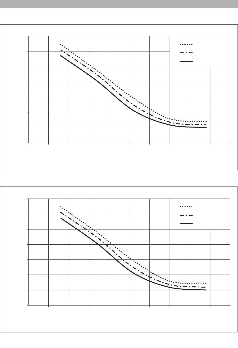
Fig. 6 Thermal Efciency Curves SSB255*
* Thermal Efciency curve is for reference only as this is a residential boiler
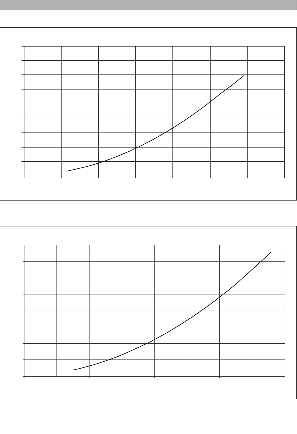
Fig. 7 Thermal Efciency Curves SSB399
Thermal Efficiency
Return Water Temperature (°F) @ 36 Degree Rise
86%
88%
90%
92%
94%
96%
98%
100%
70 80 90 100 110 120 130 140 150 160 170
100% input
30% input
20% input
Thermal Efficiency
Return Water Temperature (°F) @ 36 Degree Rise
86%
88%
90%
92%
94%
96%
98%
100%
70 80 90 100 110 120 130 140 150 160 170
100% input
30% input
20% input
6720818454 (2016/02) USSSB
12 | Product description
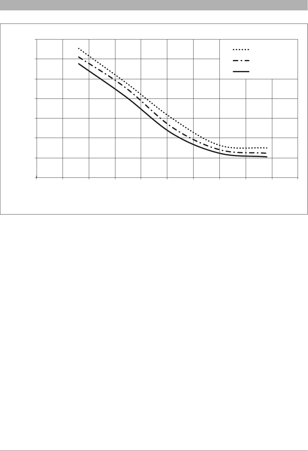
Fig. 8 Thermal Efciency Curves SSB512
Thermal Efficiency
Return Water Temperature (°F) @ 36 Degree Rise
86%
88%
90%
92%
94%
96%
98%
100%
70 80 90 100 110 120 130 140 150 160 170
100% input
30% input
20% input
SSB6720818454 (2016/02) US
Regulations | 13
3 Regulations
Observe all rules, regulations, standards and guidelines
applicable to the installation and operation of this appliance
in your country.
In the Commonwealth of Massachusetts, this appliance
must be installed by a licensed plumber or gas tter. Valves
external to the boiler must be tted with T-handles and
condensate piping must be installed in accordance with the
State Plumbing Code.
3.1 Compliance with standards and regulations
The installation must conform to the requirements of the authority having
jurisdiction or, in the absence of such requirements, to the latest edition
of the National Fuel Gas Code, ANSI Z223.1./NFPA 54. In Canada,
installation must be in accordance with the requirements of CAN/CSA
B149.1, Natural Gas and Propane Installation Code.
This condensing gas boiler complies in its design and mode of operation
with the American National Standard ANSI Z21.13/CSA4.9, latest edition
for Gas Fired Low Pressure Steam and Hot Water Boilers.
Other conrmed approvals and certications are indicated by labels on
the boiler.
Where required by the authority having jurisdiction, the installation
must conform to the Standard for Controls and Safety Devices for
Automatically Fired Boilers, ANSI/ASME CSD-1.
Install CO detectors per local regulations. Boiler requires yearly
maintenance (see section “7 Maintenance”).
3.2 Operating limits of the boiler
The heat exchanger has been designed and certied in accordance with
the ASME Boiler and Pressure Vessel Code, Section IV.
The hot water distribution system must comply with all applicable codes
and regulations. When replacing an existing boiler, it is important to
check the condition of the entire hot water distribution system to ensure
safe operation. Common practice calls for inspecting an existing system
in its entirety and bringing it up to code. All pipework should be properly
cleaned and ushed.
3.3 Additional regulations for installation in
Massachusetts
(a) For all side wall horizontally vented gas fueled equipment installed in
every dwelling, building or structure used in whole or in part for residential
purposes, including those owned or operated by the Commonwealth and
where the side wall exhaust vent termination is less than seven (7) feet
[2150 mm] above nished grade in the area of the venting, including but
not limited to decks and porches, the following requirements shall be
satised:
• INSTALLATION OF CARBON MONOXIDE DETECTORS. At the
time of installation of the side wall horizontal vented gas fueled
equipment, the installing plumber or gastter shall observe that a hard
wired carbon monoxide detector with an alarm and battery back-
up is installed on the oor level where the gas equipment is to be
installed. In addition, the installing plumber or gastter shall observe
that a battery operated or hard wired carbon monoxide detector
with an alarm is installed on each additional level of the dwelling,
building or structure served by the side wall horizontal vented gas
fueled equipment. It shall be the responsibility of the property owner
to secure the services of qualied licensed professionals for the
installation of hard wired carbon monoxide detectors.
-In the event that the side wall horizontally vented gas fueled
equipment is installed in a crawl space or an attic, the hard wired
carbon monoxide detector with alarm and battery back-up may be
installed on the next adjacent oor level.
-In the event that the requirements of this subdivision can not be
met at the time of completion of installation, the owner shall have
a period of thirty (30) days to comply with the above requirements;
provided, however, that during said thirty (30) day period, a
battery operated carbon monoxide detector with an alarm shall be
installed.
• APPROVED CARBON MONOXIDE DETECTORS. Each carbon
monoxide detector as required in accordance with the above
provisions shall comply with NPA 720 and be ANSI/UL 2034 listed and
IAS certied.
• SIGNAGE. A metal or plastic identication plate shall be permanently
mounted to the exterior of the building at a minimum height of eight (8)
feet above grade directly in line with the exhaust vent terminal for the
horizontally vented gas fueled heating appliance or equipment. The
sign shall read, in print size no less than one-half (.) inch in size, “GAS
VENT DIRECTLY BELOW. KEEP CLEAR OF ALL OBSTRUCTIONS”.
• INSPECTION. The state or local gas inspector of the side wall
horizontally vented gas fueled equipment shall not approve the
installation unless, upon inspections, the inspector observes carbon
monoxide detectors and signage installed in accordance with the
provisions of 248 CRM 5.08(2)(a) 1 through 4.
(b) EXEMPTIONS: The following equipment is exempt from 248 CRM
5.08(2)(a) 1 through 4:
• The equipment listed in Chapter 10 entitled “Equipment Not Required
To Be Vented” in the most current edition of NFPA 54 as adopted by
the board; and
• Product Approved side wall horizontally vented gas fueled equipment
installed in a room or structure separate from the dwelling, building or
structure used in whole or in part for residential purposes.
(c) MANUFACTURERS REQUIREMENTS - GAS EQUIPMENT
VENTING SYSTEM REQUIRED. When the manufacturer of Product
Approved side wall horizontally mounted gas equipment provides a
venting system design or venting system components with the equipment,
the instructions provided by the manufacturer for the installation of the
equipment and venting shall include:
• Detailed instructions for the installation of the venting system or the
venting system components; and
• A complete parts list for the venting system design or venting system.
(d) MANUFACTURERS REQUIREMENTS - GAS EQUIPMENT
VENTING SYSTEM NOT PROVIDED. When the manufacturer of Product
Approved side wall horizontally vented gas fueled equipment does not
provide the parts for the venting of ue gases, but identies special
venting systems, the following requirements shall be satised by the
manufacturer:
• The referenced special venting systems shall be included with the
appliance or equipment installation instructions; and
• The special venting systems shall be Product Approved by the Board,
and the instructions for that system shall include a parts list and
detailed installation instructions.
(e) A copy of all instructions for all Product Approved side wall horizontally
vented gas fueled equipment, all venting instructions, all parts lists for
venting instructions, and/or venting design instructions shall remain with
the appliance or equipment at the completion of the installation.
6720818454 (2016/02) USSSB
14 | Installation
4 Installation
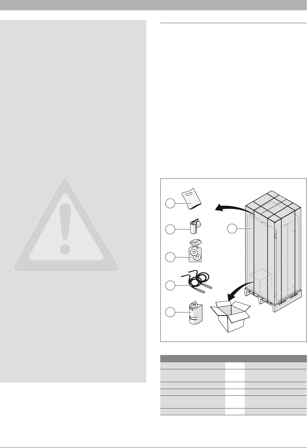
4.1 Packaging and product identication
The SSB is delivered strapped to a pallet, packed and protected in a
cardboard carton.
NOTICE: The packaging shows the characteristics of the
product: model, power, fuel type and version. In case of
deviation from the order, contact your local dealer.
After removing the packaging check the condition and
completeness of delivery.
WARNING: Keep the packing material out of reach of
children as it may be dangerous.
Dispose of packaging in an environmentally responsible
manner.
In order to ensure proper product identication do not
remove or tamper with any product identication tags or
labels.
4.2 Installation room
The boiler must be installed in rooms that comply with all local, state and
federal codes and laws. Before commissioning the boiler verify exhaust
ue and terminations are properly sealed and secured.
• Adequate combustion air and ventilation is required for safe and
proper installation of the boiler, regardless whether the combustion air
is taken from the outside (Direct Vent, sealed combustion) or inside
(room air for combustion).
WARNING: Insufcient ventilation of the boiler room can
lead to high air temperatures and lead to risk of personal
injury or death from ue gas poisoning!
• Make sure that intake and exhaust openings are sufciently sized and no
reduction or closure of openings takes place. If these are not provided, do
not operate the boiler (see section “4.7.2 Connecting ue gas systems”).
• The heating units cannot be installed outdoors. NEVER place this
appliance in a location that would subject it to temperatures at or near
freezing or temperature that exceed 120°F (49°C) while in operation.
Failure to properly locate this unit can result in premature failure.
• This appliance must be installed in a location so that any water
leaking from the unit or piping connections or relief valve openings
will not cause damage to the area surrounding the unit or any lower
oors in the structure. When such locations cannot be avoided, it
is recommended that a suitable drain pan, adequately drained, be
installed under the boiler. The pan must not restrict combustion air ow.
• When installed in a room with thin ooring, resonating noises may
occur. Isolate the boiler from direct contact with the oor to minimize
noise transmission.
• Do not allow excessive dust to collect on the appliance.
WARNING: If the information in these instructions is not
followed exactly, a re or explosion may result causing
property damage, personal injury or death.
• Do not store or use gasoline or other ammable vapors and liquids in
the proximity of this or any other appliance.
• Installation and service must be performed by a qualied installer,
service agency or the gas supplier.
• Please consider the space needed for accessibility to safety and
control devices and for performing maintenance operations.
The recommended clearance for ease of installation and service are
illustrated in the following picture:
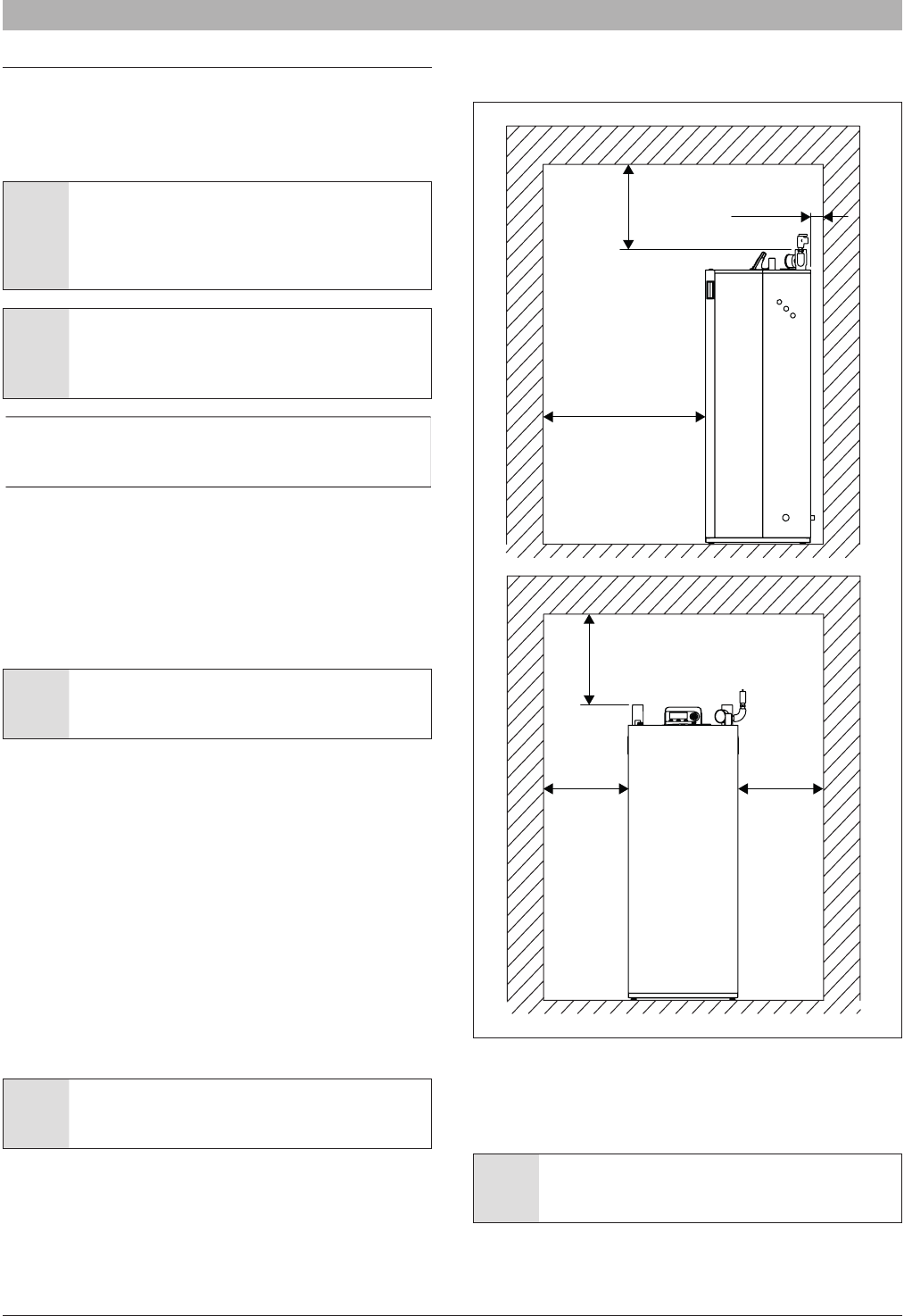
Fig. 9 Recommended minimum clearances for installation and
servicing (dimension in inches [mm])
2” (50.8 mm) clearance from combustibles is permitted, but respect the
clearance in Fig. 9 for serviceability”. The boiler can be installed on a
combustible (wood) oor excluding carpets.
NOTICE: This device is equipped with a freeze protection
function. For further information see section “5.8 Setting
frost protection”.
20” (500mm)
20” (500mm)
40” (1000mm)
2” (50mm)
4” (100mm)4” (100mm)
SSB6720818454 (2016/02) US
Installation | 15
4.3 Water Chemistry Guidelines
NOTICE: If using anti-freeze:
►Follow the boiler manufacturer’s instructions on
antifreeze concentration.
►Frost protection and inhibitor level has to be checked
annually during the regular scheduled maintenance of
the condensing boiler.
NOTICE: System damage!
►It is the installer’s responsibility to ensure that the
heating system is compatible with the boiler type and
size installed.
►pH-value of the heating water to be kept between 6.5
and 9.
To avoid any presence of oxygen in the system, it is advised to prevent as
little as possible air during installation. Usual spots where air is most likely
to seep in are: gaskets, pumps, air vents and O-rings gaskets. Using
an automatic water ll system exposes the system to fresh oxygenated
water. In commercial applications it is recommended to install a water
meter to measure the introduction of fresh water into the system.
A minimum water pressure is required for optimum performance.
Minimum water pressure required: 7.25 psi (0.5 bar).
Before and during assembly, the system must be kept free of impurities,
construction dust, sand, copper dust, grease, carbon deposits, etc., as
well as welding ux residue. In any of these instances, the old system
must be rinsed with clear water mixed with a highly concentrated rinse
agent.
For freeze protection use only propylene glycol, with scale inhibitors, with
a maximum volume [concentration] of 40% of glycol.
NOTICE: DO NOT use PVC for exhaust venting when using
anti-freeze in the primary circuit of the boiler. Use CPVC, PP
or stainless steel only!
Water hardness must fall within the following limits:
50 ppm of CaCO
3
< (alkali strength) < 150 ppm of CaCO
3
.
►Use only untreated water to ll the system.
►Do not use TSP (tri-sodium phosphate).
►Do not use ll water treated with salt bedding type exchangers (ion
exchanger).
►Never introduce non-approved boiler treatment or similar additives.
►Only use ll water with a hardness below 7 grains.
►Filling with chlorinated water is acceptable if chlorine levels are below
100 ppm.
►Consult a local water treatment specialist for recommendations if any
of the above is outside the stated ranges.
►When using oxygen permeable PEX, the system must be separated
from the boiler by a heat exchanger.
►A correctly sized and working expansion vessel must be installed.
►Do not exceed the maximum permissible ow rate through the boiler.
►Excessive ow can cause erosion damage to the heat exchanger.
►Eliminate System Leaks:
Continuous addition of make-up water will constantly add oxygen to
the system and lead to corrosion. All system leaks must be repaired.
In the following table are listed the chemical water specications.
ParametersUnitsValue
General feature-Colorless, no sediment
Dissolved Oxygenmg/l< 0,05
Total iron (Fe)mg/l< 0,3
Total copper (Cu)mg/l< 0,1
Na
2
SO
3
mg/l< 10
N
2
H
4
mg/l< 3
PO
4
mg/l< 15
Tab. 1 Water specication
4.4 Hydraulic connection
Hydraulic connection are shown in Fig. 2, Fig. 3 and Fig. 4. In the
following table are listed the pipe dimension for each model:
Model
Ø Water supply
connection
Ø Water return
connection
SSB2551-1/2” NPT male1-1/2” NPT male
SSB3991-1/2” NPT male1-1/2” NPT male
SSB5122” NPT male2” NPT male
NOTICE: Before connecting the boiler to the heating
system, ush the heating system to remove sediment, ux,
dirt, and other foreign matter. The heat exchanger may be
damaged by sediment or corrosion.
• Do not use cleaning uids that are not compatible with the boiler
materials, including acids (e.g. hydrochloric acid and similar ones) at
any concentration
• Introducing fresh water to the system increases the oxygen presence
and can cause corrosion of metallic components. Immediately repair
any drips or leaks in the system to avoid constant introduction of air
into the system.
• Do not use the water contained in the boiler for domestic use or as
drinking water or within swimming pools.
• Excessive uctuation in pressure changes in the system can cause
fatigue and stress on the heat exchanger. This is detrimental to the
integrity of the boiler and system components, it is mandatory to
maintain a constant operating pressure.
6720818454 (2016/02) USSSB
16 | Installation
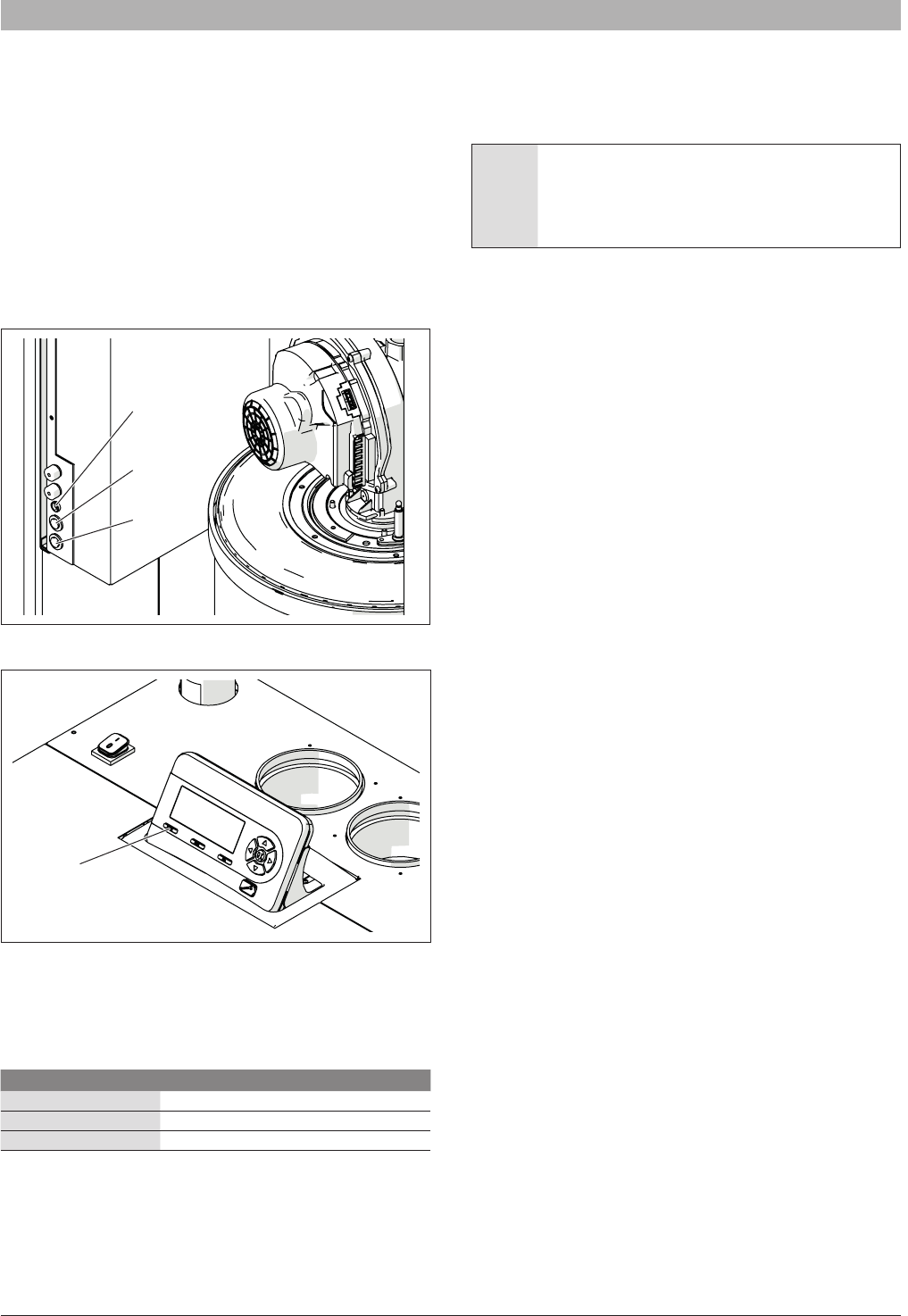
4.4.1 Low water cut off
A low water cut off (LWCO) is installed in the boiler, the manual reset
button is located on the front of the internal sliding wiring center.
To check the functionality of LWCO press the test button (the top button
shown in Fig. 10). The LED on the block will light and in the screen will
appear the error “MN: Low Water Cutoff Error”. At this point press the
reset button (the bottom button). The LED will turn off.
4.4.2 High limit safety switch
A high limit safety switch is installed in the boiler. To simulate a high limit
lockout at 208°F press the “MENU” and “OK” buttons simultaneously for
10 seconds. The control will display “MN: Max. Thermostat Lock Error”.
At this point press the reset button on the removable display to restart the
boiler.
Fig. 10
Fig. 11
4.4.3 Pressure relief valve (PRV)
The boiler is supplied with a pressure relief valve (PRV). The relief
pressure for each valve for each model of the boiler is shown in the
following table:
Boiler modelRelief Pressure
SSB25530 psi (2.07 bar)
SSB39930 psi (2.07 bar)
SSB51275 psi (5.17 bar)
A 75psi pressure relief valve can be purchased separately and eld
installed.
The pressure relief valve (PRV) must be piped to a suitable drain to
prevent injury if the valve releases. Use a pipe of the same diameter of
the outlet of the valve
4.4.4 Expansion tank
An expansion tank must be installed in the hydraulic system. The
expansion tank must be properly sized for the boiler and the system
volume, temperature and pressure.
WARNING: An undersized expansion tank will cause
leakage of water from the pressure relief valve and
introduce fresh water into the system. Excessive addition of
makeup water can cause corrosion of metallic components
and compromise the functionality of the boiler.
Refer to instructions provided by the manufacturer of the expansion tank
for details on its installation and sizing.
LED
Test
Reset
Reset
SSB6720818454 (2016/02) US
Installation | 17
4.4.5 Pump
SSB boilers must be tted with a circulator pump. The graph in the following gure shows the pressure drop through the boiler circuit depending on the
ow rate.
SSB255
0
1
2
3
4
5
6
7
8
05101520
∆ p/ Feet of Head
Flowrate / GPM
Fig. 12 SSB255 Pressure drop
It is important to ensure the pump has the correct ow rate
for the system to avoid a low water circulation situation. In
event of an inadequate ow rate, the safety devices of the
boiler will automatically stop the burner.
6720818454 (2016/02) USSSB
18 | Installation
SSB399
0
2
4
6
8
10
12
14
16
18
05101520253035
∆ p/ Feet of Head
Flowrate / GPM
Fig. 13 SSB399 Pressure drop
SSB512
0
5
10
15
20
25
30
35
40
0510152025303540
∆ p/ Feet of Head
Flowrate / GPM
Fig. 14 SSB512 Pressure drop
SSB6720818454 (2016/02) US
Installation | 19
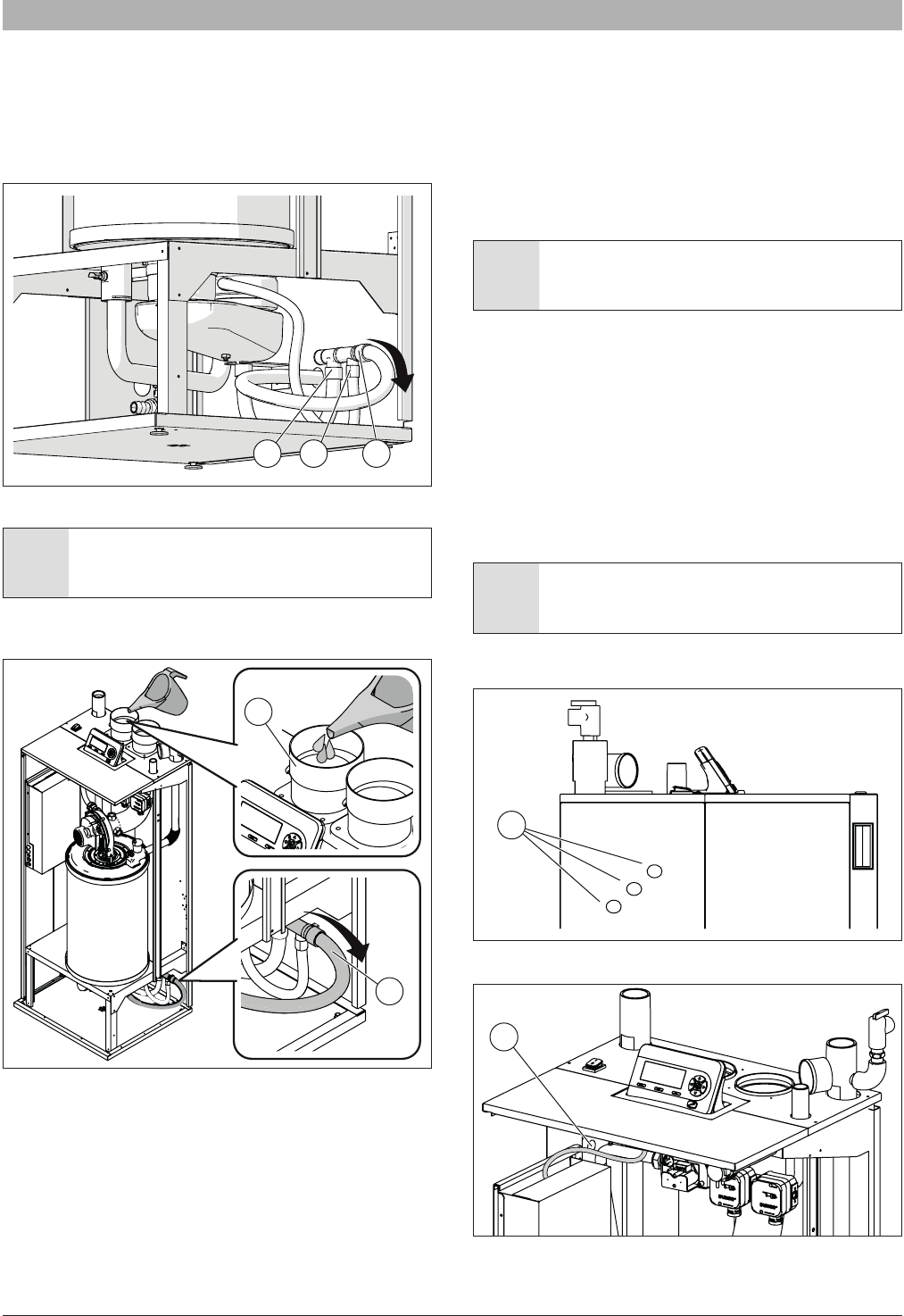
4.4.6 Condensate removal
The condensate water produced by the boiler during its normal operation
is collected by two plastic pipes (A and B) provided with the boiler and
connected with a plastic collector inside the case. A third tube (C) collects
the condensate output from the collector [Arrow is the direction of ow of
condensate].
Fig. 15
DANGER: The condensate pipe A and B, shown in Fig. 15,
must be lled with water or combustion gases will enter the
room with a risk of an excessive level of carbon monoxide.
To ll the condensate discharge add water from the vent (1) until you see
water come out of the condensate discharge pipe (2).
Fig. 16
The condensate water shall be discharged at atmospheric pressure,
i.e. by dripping into a siphon-shaped container connected to the home
sewage system or suitable drain, and shall be neutralized prior to draining
per local codes.
The boiler is equipped with three holes (in the right, left and back side) to
carry the condensate out the condensate drain tube.
Install the condensate drain tube through the appropriate hole and be
sure to pitch away from the boiler.
• Do not reduce the diameter of the condensate drain pipe down
stream.
• Never use copper pipes or of other material not intended for the
specic purpose, because the action of condensate will cause a rapid
deterioration.
• Check that the condensate drain pipe is adequately sloping towards
the discharge point avoiding high points, which can inhibit the ow of
condensate.
• Install the condensate pipe in such a way so as to avoid the freezing
of the liquid.
NOTICE: Verify condensate disposal / neutralization is in
accordance with local, state and federal regulations.
A condensate removal pump is required if the boiler is below the drain.
When installing a condensate pump, select one approved for use with
condensing boilers and furnaces. The pump should have an overow
switch to prevent property damage from condensate leakage.
4.5 Electrical connection
4.5.1 Power supply cable connection
To connect the boiler to the electrical supply, as required by local, state
and federal codes, provide and install a service switch (15 amp is
recommended).
The power supply cable can be inserted into the boiler using one of the
six knock out holes (A) on the sides as shown in Fig. 17.
WARNING: All the electrical wiring must be secured by
appropriate strain reliefs.
To secure the supply cable inside of the boiler use the cable clamp shown
in position B shown in Fig. 18.
Fig. 17
Fig. 18
ABC
H
2
O
1
H
2
O
2
A
B
6720818454 (2016/02) USSSB
20 | Installation
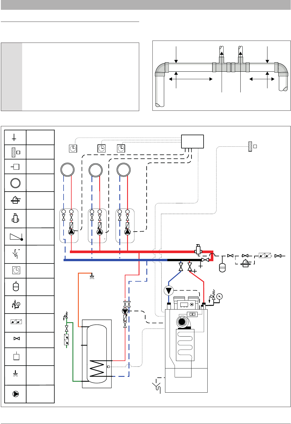
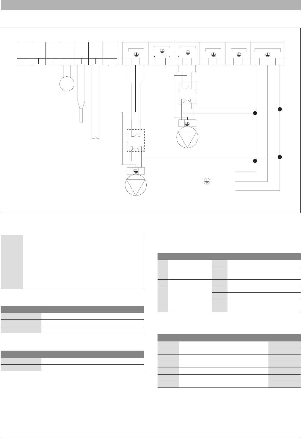
The general electrical connection is shown in the following diagram :
Fig. 19
(*) NOTICE: The maximum amp load for each pump is 1 A
when 2 or 3 pumps are connected. For this reason, if the
power consumption of each pump is higher than 84 watt,
use a relay as shown in gure.
If just one pump is connected, the maximum amp load
of this single pump is 2 A. For this reason if the power
consumption of the pump is higher than 168 watt, use a
relay as shown in gure Fig. 19.
(**) NOTICE: line voltage.
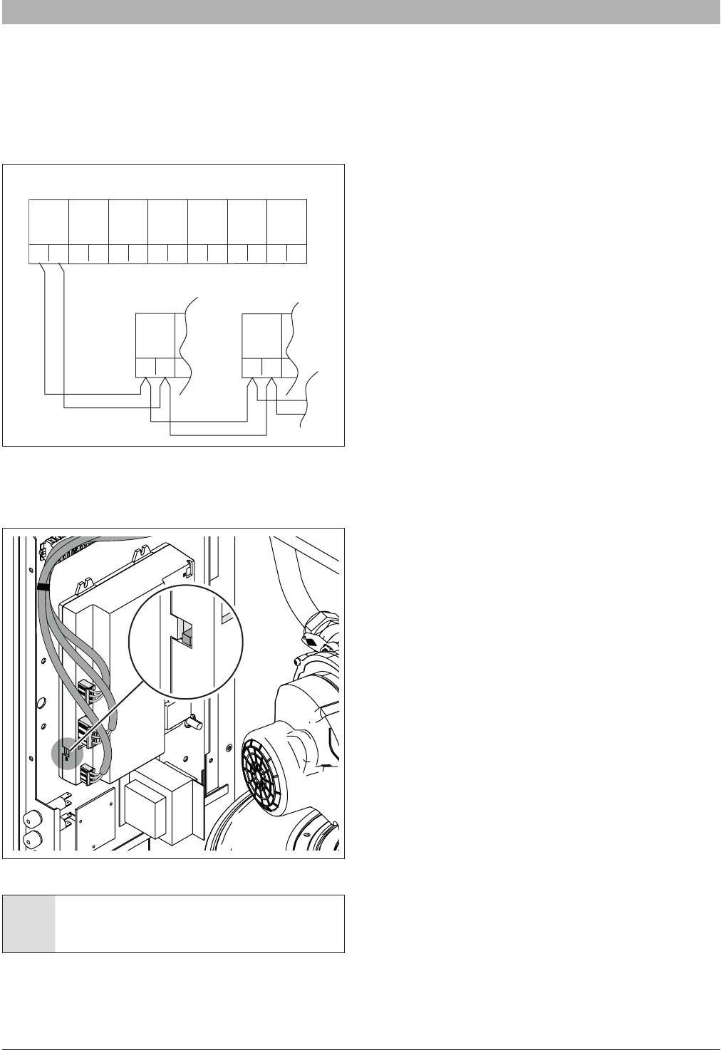
4.5.2 Access to the electrical terminal strip
To have access to the internal terminal strip of the boiler follow the steps
below (see Fig. 20).
►Rotate the lock at the top on the front panel and remove the front
panel as shown.
►Slide out the electrical box and remove the two screw from the front.
►Remove the box cover to have access to the terminal strip.
Fig. 20
4.5.3 Room thermostat connection
Connect the thermostat to terminals 11 and 12 as shown in Fig. 19.
4.5.4 Outside temperature sensor
If outside temperature control is to be used, the outside probe needs
to be connected to terminals 7 and 8 as shown in Fig. 19. The outside
probe shall be installed on an outer wall, North or North/East, away from
windows, door, and ventilation grids. Never install the probe in a position
exposed to the sun.
The maximum length is 300’ (100 meter), if the cable length exceeds
32’ (10 meters) a shielded cable is required and shall be connected to
chassis ground.
NOTICE: All Sensors and low voltage wiring shall not be
routed in direct contact or near high voltage power.
123
45
6
7
89
1011121314
101102103104105106107108109
116118117
L
N
L
N
L
N
CASCADE
LINK
MOD
BUS
Gas
Switch
Out
Door
DHW Tank
Sensor
Room
Thermostat
Supply
Sensor
Boiler
Pump
Pump DHW
120 V Main in
N
L
Boiler pump
DHW tank pump
Room thermostat
DHW tank sensor
or aquastat
Outdoor sensor
110111112
L
N
Alarm
113114115
L
N
120 V Aux
L
N
Pump CH
N
L
3 Way
120 V Neutral
Ground
120 V Line
Supply sensor
N
L
Relay (*)
Furnished and
Installed by others
Relay (*)
Furnished and
Installed by others
(**)
Relay (*)
Furnished
and
Installed
by others
System pump
SSB6720818454 (2016/02) US
Installation | 21
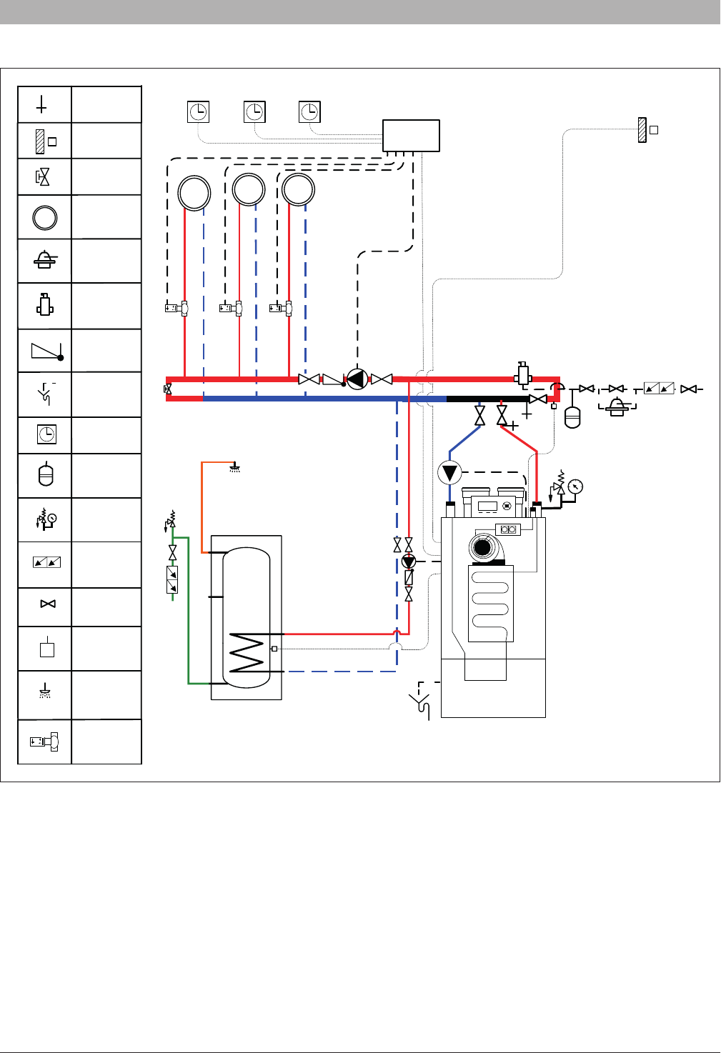
4.5.5 Electrical wiring diagram
Fig. 21 Wiring diagram
bl
24 V
24V
L
N
brn
brn
brn
brn
brn
blu
w
blu
blu
brn
blu
brn
blu
bl
bl
brn
w
w
w
9
7
8
CASCADE
LINK
65
12
10
1112
Room
brn
blu
brn
blu
brn
blu
brn
blu
N
118
L
116
117
13
14
brn
blu
w
bl
N
L
103101102
106104105
115113114
NL
113114115
SSB512 ONLY
SSB255 ONLY - SSB399 ONLY
NL
brn
w
bl
w
w
bl
w
bl
brn
blu
NLNL
NLL
109107108
112
110
111
GND
GND
GND
blw
bl
w
w
bl
blw
w
w
w
bl
bl
w
bl
bl
w
bl
blubrn
blblugbrn
34
bl
bl
blu
brn
o
blu
GND
Ther-
mostat
Manual Reset Switch
(Normally Closed,
Opens to Reset)
Alternate Chassis
Ground Connection
External Test Switch
(Normally Closed,
Opens to Test)
RESET
GND
AC COMMON
TEST
24 VAC HOT
PROBE
P
CHASSIS
GROUND
(Via Boiler / Piping)
AR1
AR1
120V
24V
210
210
210
208
208
208
209
209
209
214
214
214
HIGH VOLTAGE
LOW VOLTAGE
IN / OUT
HIGH
Tank
Sensor
OUT
DOOR
MOD
BUS
GAS
SWITCH
120 V
MAIN IN
Supply
Sensor
HIGH VOLTAGE
OUT
MAIN PUMP
120 V AUX
PRESSURE
SWITCH
MIN
PRESSURE
SWITCH
MAX
ALLARM
VOLTAGE
PRESSURE
SWITCH
FLUE
PUMP CH
3 WAY
PUMP DHW
DHW
brn= CABLE BROWN
blu= CABLE BLUE
bl= CABLE BLACK
w= CABLE WHITE
o= CABLE ORANGE
g= CABLE GRAY
L= LINE
N= NEUTRAL
grn/yel = Ground
6720818454 (2016/02) USSSB
22 | Installation
4.6 Gas supply piping
Verify that the type and the pressure of the gas supplied correspond with
those required for the boiler. When eld converting the boiler from Natural
to LP gas be sure to adhere the new gas label on the boiler.
The minimum and maximum pressure for natural gas are 3.5” W.C. (8.72
mbar) and 10.5” W.C. (26.15 mbar) respectively.
The minimum and maximum pressure for LP gas are 8” W.C. (19.9 mbar)
and 13” W.C. (32.3 mbar) respectively.
4.6.1 Connection of gas supply piping
Connect the gas supply to the unit as follows:
►Install a ground joint union for servicing as required.
►Install a manual shutoff valve in the gas supply piping
►Install a sediment trap/ drip leg
►Purge all air from the gas supply piping.
►Before placing the appliance in operation, check the appliance and its
gas connection.
►Check the appliance and its gas connection with a leak test before
placing in operation.
WARNING: Gas piping must be supported with proper
hangers and not from the boiler itself or its devices and
accessories.
DANGER: Never use an open ame to test for gas leaks.
Always use an approved leak detection method.
WARNING: Failure to properly apply pipe sealing
compound can result in severe personal injury, death, or
substantial property damage.
The Commonwealth of Massachusettes prohibits the use of copper tubing
for the gas line.
4.6.2 Gas type conversion
DANGER: Personal injury and property damage.
►This conversion shall only be performed by a trained and
certied installer in accordance with the manufacturer‘s
instructions and all applicable codes and requirements
of the authority having jurisdiction.
►If the information in these instructions is not followed
exactly, or the installation, adjustment, modication,
operation or maintenance is carried out by an
unqualied person, a re, explosion or generation of
large amounts of carbon monoxide may result causing
property damage, personal injury or loss of life.
►Before carrying out electrical work: Disconnect the
appliance from the power supply at the emergency
shutoff switch or by disengaging the heating system
circuit breaker. Take appropriate measures to prevent
accidental reconnection.
►The installer is resp onsible for the proper conversion of
this appliance.
►The conversion is not complete until the operation of the
converted appliance is checked as specied in these
instructions.
The gas-air ratio must always be set on the basis of a CO
2
or O
2
reading taken at maximum nominal output and minimum nominal
output using an electronic ue gas analyzer.
LP conversion kit installation (SSB255)
Natural Gas to LP conversion
The heating unit is factory preset for operating with natural gas. This
set-up can be changed using the conversion kits supplied by the
manufacturer.
NOTICE: This change may only be performed by a qualied
installer or service technician, according to the following
procedure.
Switching from NATURAL GAS to LP
►Close the gas cock
►Disconnect the electric power supply from the boiler
WARNING: to avoid electrical shock, it is mandatory to
disconnect the boiler from the power supply using a service
disconnect external switch.
►Remove the front panel
►Unscrew the 3 screws ‘A’ and the swivel joint ‘B’ indicated in Fig. 22 to
separate the valve from the fan
►Separating the two components, you can see the hole where the gas
passes with its gasket
►Insert the provided metal orice ‘C’ into the gasket “D” without
removing the gasket itself
►Check the condition of the gasket ‘E’. Replace if necessary
►Tighten the swivel joint ‘B’
►Tighten the 3 screws ‘A’
►Switch the main power supply to ON
Fig. 22
NOTICE: Make sure there is no demand or call for heat.
►Use the control panel to enter in the parameter list and change the
parameter N° 98 (Gas Type) from “NG” to “LPG”
►Reopen the gas shut-off cock
►Adjust the CO
2
parameter as explained in chapter “5.7 Adjusting
and setting CO2 limits” (see “Tab. 17 Number of turns for gas valve
settings”)
►Afx the gas type label from the gas conversion kit to the appliance
(Fig. 24).
ABCED
SSB6720818454 (2016/02) US
Installation | 23
LP conversion kit installation (SSB399 - SSB512)
Natural Gas to LP conversion
The heating unit is factory preset for operating with natural gas. This
set-up can be changed using the conversion kits supplied by the
manufacturer.
NOTICE: This change may only be performed by a qualied
installer or service technician, according to the following
procedure.
Switching from NATURAL GAS to LP
►Close the gas cock
►Disconnect the electric power supply from the boiler
WARNING: to avoid electrical shock, it is mandatory to
disconnect the boiler from the power supply using a service
disconnect external switch.
►Remove the front panel
►Unscrew the swivel joint ‘A’ indicated in Fig. 23 to separate the valve
from the connection pipe with the fan
►Separating the two components, you can see the hole where the gas
passes with its gasket
►Place the provided metal orice ‘B’ (Fig. 23) between the two gaskets
►Tighten the swivel joint
►Switch the main power supply to ON
Fig. 23
(*) Balancing tube shown removed for clarity.
Boiler modelN° on orice
SSB2557.0
SSB39910.5
SSB5129.5
Tab. 2
F
NOTICE: Make sure there is no demand or call for heat.
►Use the control panel to enter in the parameter list and change the
parameter N° 98 (Gas Type) from “NG” to “LPG”
►Reopen the gas shut-off cock
►Adjust the CO
2
parameter as explained in chapter “5.7 Adjusting
and setting CO2 limits” (see “Tab. 17 Number of turns for gas valve
settings”)
►Afx the gas type label from the gas conversion kit to the appliance
(Fig. 24).
Fig. 24 Afxing the gas type label
4.7 Venting and air piping system
WARNING: Do not connect this gas appliance with any
other appliance unless approved by manufacturer.
Failure to comply with this WARNING could result in the
accumulation of carbon monoxide gas which can cause
severe personal injury or death.
DANGER: The condensate discharge must be lled with
water or combustion gases will enter the room with a risk of
an excessive level of carbon monoxide. For instruction see
par 4.4.6.
NOTICE: DO NOT use PVC for vent piping when using
anti-freeze in the primary circuit of the boiler. Use CPVC, PP
or stainless steel only!.
Make sure that the combustion air is not contaminated by:
• Permanent wave solutions;
• Chlorinated waxes/cleaners;
• Chlorine-based swimming pool chemicals;
• Calcium chloride
• Sodium chloride used for water softening;
• Refrigerant leaks;
• Paint or varnish removers;
• Hydrochloric acid/muriatic acid;
• Cements and glues;
• Antistatic fabric softeners used in clothes dryers;
• Chlorine-type bleaches, detergents, and cleaning solvents found in
household laundry rooms;
• Adhesives used to fasten building products and other similar products.
To prevent contamination do not connect the combustion ait inlet and
exhaust near:
• Dry cleaning/laundry areas and establishments;
• Swimming pools;
• Metal fabrication plants;
• Beauty shops;
• Refrigeration repair shops;
• Photo processing plants;
• Auto body shops;
• Plastic manufacturing plants;
• Furniture renishing areas and establishments;
A
B
(*)
DIRECT VENT BOILER FOR EITHER DIRECT VENT INSTALLATION OR FOR
INSTALLATION USING INDOOR COMBUSTION AIR
CHAUDIÈRE À ÉVENT DIRECT PUT INSTALLATION AVEC ÈVACUATION
DIRECTE OU AVEC AIR COMBURANT
Catégorie
Modèle
Référence
Category
Model
Model no.
IV
SSB-512
7 738 004 896
Converted to LPG (Propane) with conversion kit X XXX XXX XXX
CO
2 (max. rate/ min rate)
Min. inlet gas pressure
Max. inlet gas pressure
Mainfold pressure
Min. input rate
Max. input rate
Output rate
Minimun relief valve capacity
Altitude
10,7/10,3 %
8,0 in.W. C.1,99 kPa
3,23 kPa
30,0 kW
150,0kW
144,0 kW
13,0 in.W. C.
cfactory set - not adjustable
102,360 Btu/hr
511,800 Btu/hr
491,328 Btu/hr
0-2000 ft0-610 m
(Refer to installation instruction for higher altitudes)
This boiler was converted on(day - month - year)
(name and address of organization making this conversion), which accepts
the responsability that this conversion has been properly made.
togas. By
IV
SSB-512
7 738 004 896
Convertie vers LPG (Propane) a vec le kit de conversion X XXX XXX XXX
CO
2 ( max / min)
Min. pression d’alimentation en gaz
Max. pression d’alimentation en gaz
Pression à la conduite de gaz
Consommation calorifique min.
Consommation calorifique max.
Puissance utile nominal
Capacité minimale de la soupape de sécurité
Altitude
232,1 kg/hr511,8 lbs/hr
10,7/10,3 %
8,0 in.W. C.
150,0kW
144,0 kW
13,0 in.W. C.
cfactory set - not adjustable
102,360 Btu/hr
511,800 Btu/hr
491,328 Btu/hr
0-2000 ft0-610 m
232,1 kg/hr511,8 lbs/hr
(Se référ à la notice d’installtion en cas d’altitude plis élevée)
Ce appareil a été converti le(jour- mois- année) en
(nome ed adtrsse de l’organisme effectuant cette conversion), qui accepte la
responsabilité de la bonne execution de cette conversion.
gazpar
X XXX XXX XXX (2015/04)
6720818454 (2016/02) USSSB
24 | Installation
• Remodeling areas;
• Garages with workshops.
4.7.1 General venting and combustion air piping system
The SSB boilers require an approved vent system-designed for positive
pressure.
Vent connectors serving appliances vented by natural draft shall not be
connected to any portion of mechanical draft systems operating under
positive pressure.
Ensure that the ue pipes and seals are not damaged.
Use only primer and glue compounds approved for use with the vent
material used.
Never install a barometric or a thermally controlled vent damper with this boiler.
Do not route the ue system piping through or inside another duct that is
used for exhausting air or other ue gases.
The condensate trap must be primed at all times. Failure to do so may
allow combustion gases to escape into boiler room.
The unit is to be used for either direct vent installation or for installation
using room air for combustion. When room air is used, it is necessary to
provide an adequate opening for the fresh air intake.
You must use any of the vent/air piping methods shown in this manual.
Be sure to locate the unit such that the vent and combustion air piping
can be routed through the building and properly terminated.
The boiler / vent installation must be in accordance with Venting
of Appliances, of the latest edition of the National Fuel Gas Code,
ANSI Z223.1/NFPA 54 or section, Venting Systems and Air Supply
for Appliances, of the CAN/CSA B149.1, Natural Gas and Propane
Installation code or applicable provisions of the local, state and federal
building codes.
All vent pipes must be installed according to the vent manufacturer’s
instructions.
The exhaust vent and the combustion air inlet lines must be supported to
prevent sagging per the vent manufacturer’s instructions.
Do not mix components from different systems. The vent system could
fail, causing leakage of ue products into the living space. Use only
approved materials.
Use of cellular core PVC and CPVC for venting system is not allowed.
WARNING: Improper venting due to failure to comply with
the warnings above can result in excessive levels of carbon
monoxide!
The exhaust pipe must be pitched a minimum of a 1/4 inch per foot back
to the boiler (to allow drainage of condensate).
The vent system shall be installed so as to prevent the accumulation of
condensate.
Consult local and state codes pertaining to special building code and re
department requirements. Adhere to national code requirements.
Observe the listed maximum lengths of vent system, which are boiler
model dependent
To avoid moisture and frost build-up and to maintain clearances to openings
on adjacent structures, 45 ° and 90 ° elbows or tees may be attached to
the end of the vent termination pipe to direct exhaust plumes away from
the adjacent structure. The total allowable vent length, maximum number of
elbows and distance to air intake restrictions must be adhered to.
Due to the high efciency of the unit it may discharge what looks like
white smoke especially when the outside air temperature is cold. This
is due to the presence of water vapor, normally present in the exhaust
gases.
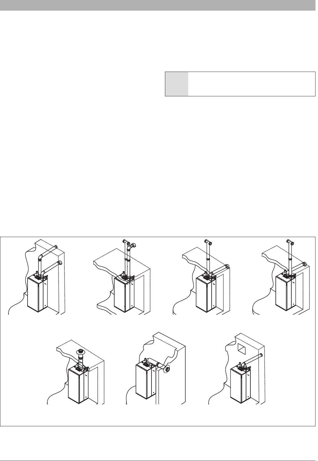
The following gure shows the acceptable piping installation for venting
and combustion air.
Fig. 25
Two pipes side wall
(Direct venting)
Two pipes vertical
(Direct venting)
Air intake side wall,
vent vertical
(Direct venting)
Air intake vertical,
vent side wall
(Direct venting)
Concentring
vertical pipe
(Direct venting)
Concentring side
wall pipe
(Direct venting)
One pipe venting
side wall (or vertical)
(Not direct venting)
SSB6720818454 (2016/02) US
Installation | 25
4.7.2 Connecting ue gas systems
Optional vent systems are:
• Twin pipe, concentric pipe and 1 pipe using room air
• Approved materials PVC, CPVC, Stainless Steel, PP and PP-Flex
(M&G Duravent PolyPro and Centrotherm InnoFlue)
• Sealed combustion or room air intake
• Terminations can be either horizontal or vertical
• The diameters of the ue outlet and combustion air intake inlet are
designed to t standard PP, PVC, CPVC and stainless steel pipes.
The following table gives the diameter of the ue adapter on the
boiler.
BoilerSSB255SSB399SSB512
Diameters3” - 80mm4” - 100mm4” - 100mm
Tab. 3
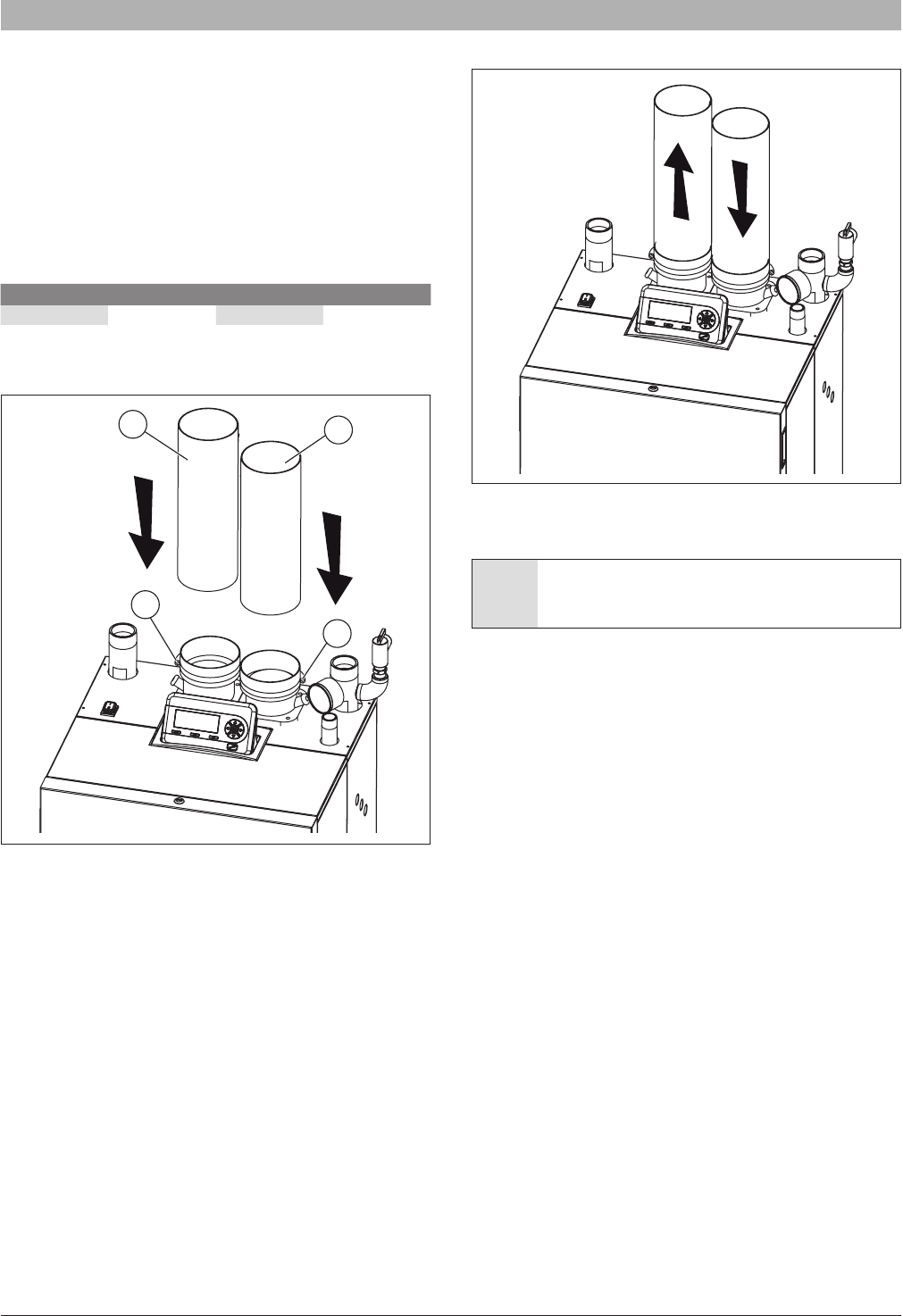
Insert the exhaust pipe and the air intake pipe as shown in the following
gure:
Fig. 26
Insert the ue exhaust pipe “A” completely into the adapter and tighten
the clamp “B” present in the ue exhaust adapter.
Insert the air intake pipe “C” completely into the adapter and tighten the
clamp “D” present in the air intake adapter.
The correct ow direction into two pipes is shown in Fig. 27.
Fig. 27
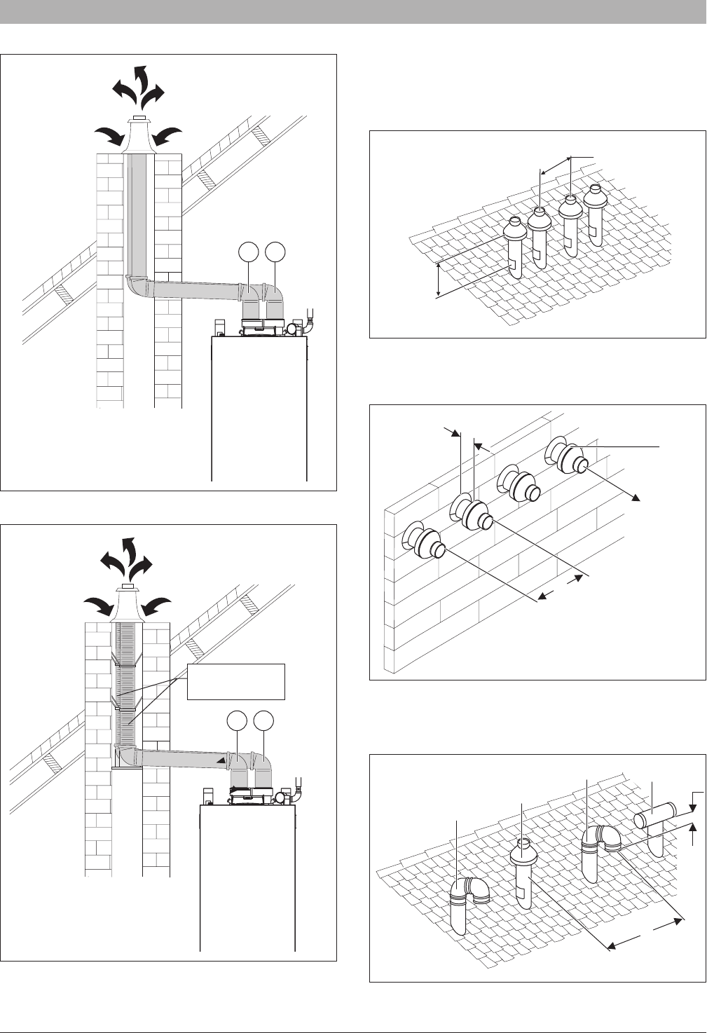
4.7.3 Installation of the exhaust and air intake system
NOTICE: Do not extend exposed vent pipe outside the
building beyond recommended distance of 39” or 1 meter.
Condensate could freeze and block vent pipe
Vent should terminate at least 3 feet (915 mm) away from adjacent walls,
inside corners and 5 feet (1525 mm) below roof overhang ( [X2], [X4], see
Fig. 28)
C
A
B
D
6720818454 (2016/02) USSSB
26 | Installation
Fig. 28
X
1
X
2
X
3
X
4
X
5
X
1
X
1
X
2
X
3
X
3
1
2
Y
A
Y
B
Y
A
3
3
3
3
Direct vent (sealed combustion)
[1] Forced air inlet
[2] Gravity air inlet
[3] Exhaust terminal
X1 1 foot (305 mm)
X2 See Note 1)
X3 1 foot (305 mm) USA
3 feet (915 mm) Canada
X4 See Note 1)
X5 7 feet (2135 mm) (see Note 2)
YA At least 1 foot (305 mm) above grade or snow line
YB Exhaust terminal must be at least:
3 feet (915 mm) above forced air inlet within
10 feet (3050 mm) horizontally – USA
6 feet (915 mm) above forced air inlet - Canada
Fan assisted appliance (Room air for combustion)
[1] Forced air inlet
[2] Gravity air inlet
[3] Exhaust terminal
X1 1 foot (305 mm)
X2 See Note 1)
X3 1 foot (305 mm) USA
3 feet (915 mm) Canada
X4 See Note 1)
X5 7 feet (2135 mm) (see Note 2)
YA At least 1 foot (305 mm) above grade or snow line
YB Exhaust terminal must be at least:
3 feet (915 mm) above forced air inlet within
10 feet (3050 mm) horizontally – USA
6 feet (915 mm) above forced air inlet - Canada
It is not recommended to terminate vent above any door or window,
condensate can freeze causing ice formations.
Do not use chimney as a raceway if another boiler or replace is vented
into or through chimney.
All PVC/CPVC vent pipes must be glued, except for the ue gas adapter
pipe connection.
DO NOT use PVC when using anti-freeze in the primary circuit of the
boiler. Use CPVC, PP or stainless steel only!
Vent terminations must keep the following minimum clearances from
electric meters, gas meters, regulators and relief equipment: 4 feet (1220
mm) [Canada 6 feet (1830 mm)] horizontally and in no case above and
below, unless a horizontal distance of 4 feet (1220 mm) [Canada 6 feet
(1830 mm)] is maintained.
NOTES:
1) For Clearances not specied in ANSI Z223.1 / NFPA
54 or CSA B149.1 Clearance in accordance with local
installation codes and the requirements of the gas supplier
including the Authority having jurisdiction.
2) A vent shall not terminate directly above a sidewalk or
paved driveway that is located between 2 single family
dwellings and serves both dwellings.
SSB6720818454 (2016/02) US
Installation | 27
Pipe diameter per boiler
MaterialItemStandard [USA]
Standard
[Canada]
SSB
255
SSB
399
SSB
512
PVC schedule 40,
80
1
Flue gas or
combustion air
ANSI/ASTM D1785
BH Gas venting
systems,
ULC S636
2
,
Class IIA - PVC,
Class IIB - CPVC,
Class IIC -
Polypropylene
3” (80mm)
4” (100mm)
3” (80mm)
4” (100mm)
4” (100mm)
PVC-DWV
Flue gas or
combustion air
ANSI/ASTM D2665
3” (80mm)
4” (100mm)
4” (100mm)4” (100mm)
CPVC schedule
40, 80
Flue gas or
combustion air
ANSI/ASTM F441
3” (80mm)
4” (100mm)
4” (100mm)4” (100mm)
PP
Flue gas or
combustion air
ANSI Cat IV
Approved
Polypropylene
3” (80mm)
4” (100mm)
4” (100mm)
5” (130mm)
4” (100mm)
5” (130mm)
PP-Flex
Flue gas or
combustion air
ANSI Cat IV
Approved
Polypropylene
3” (80mm)
4” (100mm)
4” (100mm)
5” (130mm)
4” (100mm)
5” (130mm)
Stainless Steel
AL29-4C
Flue gas or
combustion air
UL1738
3” (80mm)
4” (100mm)
4” (100mm)
5” (130mm)
4” (100mm)
5” (130mm)
PVC
Pipe cement/
primer
ANSI/ASTM D2564XXX
CPVC
Pipe cement/
primer
ANSI/ASTM F493XXX
Tab. 4 Approved Flue gas or combustion air materials and ttings per boiler
1 PVC must not be used for vent material when a glycol mixture is used in the boiler circuit.
2 Components of the certied vent systems must not be interchanged with other vent systems or unlisted pipe ttings. Plastic components, and specied
primers and glues of the certied vent system must be from a single system manufacturer and not intermixed with other system manufacturer’s vent
system parts. For installations in Canada, eld supplied plastic vent piping must comply with CAN/CSA B149.1 (latest edition) and be certied to the
Standard for Type BH Gas Venting systems. ULC S636.
The supplied vent connector and separate available vent terminations are certied as a part of the boiler.
Standard straight pipes, 90°-elbows or Tees are approved as roof or wall terminations in all the approved materials. Furthermore the following terminations
are approved. For details please refer to the supplier’s information.
Roof TerminalMaterialSupplierPart Number
3” (125 mm)
4” (100mm)
Concentric kits
PVC or CPVC
IPEX System 636
Type IIa & IIb
196006 (PVC), 197009 (CPVC)
196021 (PVC), 197021 (CPVC)
3” / 5” (80/125 mm)
concentric
PP
M&G Duravent PolyPro
or
Centrotherm InnoFlue
3PPS-VKL (M&G Duravent)
or
ICRT3539 (Centrotherm)
4”/6” (100/150 mm)
Concentric
PP
M&G Duravent PolyPro
or
Centrotherm InnoFlue
4PPK-VKL (M&G Duravent)
or
ICRT 4679 (Centrotherm)
3” (80 mm)
Chimney Cap
PP Flex
M&G Duravent PolyPro
or
Centrotherm InnoFlue
3PPS-FKL (M&G Duravent)
or
ISCP03 (Centrotherm)
4” (100 mm)
Chimney Cap
PP Flex
M&G Duravent - PolyPro
Centrotherm - Innoue
SW Flex
4PPS-FKL (M&G Duravent)
or
ISCP04 (Centrotherm)
5” (130 mm)
6” (150 mm)
8” (200 mm)
Vertical termination for commercial
systems
PPM&G Duravent - PolyPro
5PPS-VTM
6PPS-VTM
8PPS-VTM
Tab. 5 Roof terminals
6720818454 (2016/02) USSSB
28 | Installation
Wall TerminalMaterialSupplierPart Number
3" (80 mm)parallel stainless steelFlex-L46546901
3” (125 mm)
4” (100mm)
Concentric kits
PVC or CPVCIPEX IIa
196006 (PVC), 197009 (CPVC)
196021 (PVC), 197021 (CPVC)
3” (125mm)
Wall termination kit
PVCIPEX IIa081219
3” (125 mm)
4” (100mm)
Low prole termination kit
PVCIPEX IIa
196985
196986
3” (80 mm)
twin pipe termination
PVC/parallel stainless steelANSI/ASTM D1785 or Field Controls46600203
4” (100 mm)
twin pipe termination
PVC/parallel stainless steelANSI/ASTM D1785 or Field Controls46600204
38 | Commissioning (for single boiler application)
NumberDescriptionUnitDefaultMinMaxStep
93Fan Speed MinimumRPM***60
94Fan Speed IgnitionRPM***60
97Appliance Model **-*161
98Gas Type -NGNGLPG
99Flue length range-1141
Tab. 15 Level 2 parameters
(*) Depend on appliance type
(**) The value for this parameter is:
• 1 for SSB512
• 2 for SSB399
• 3 for SSB225
SSB6720818454 (2016/02) US
Commissioning (for single boiler application) | 39
5.7 Adjusting and setting CO
2
limits
NOTICE:
Please verify parameter 99 is to be set rst.
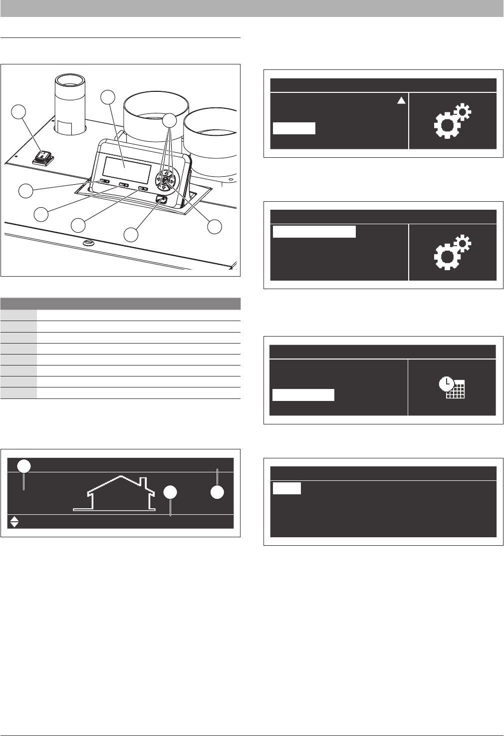
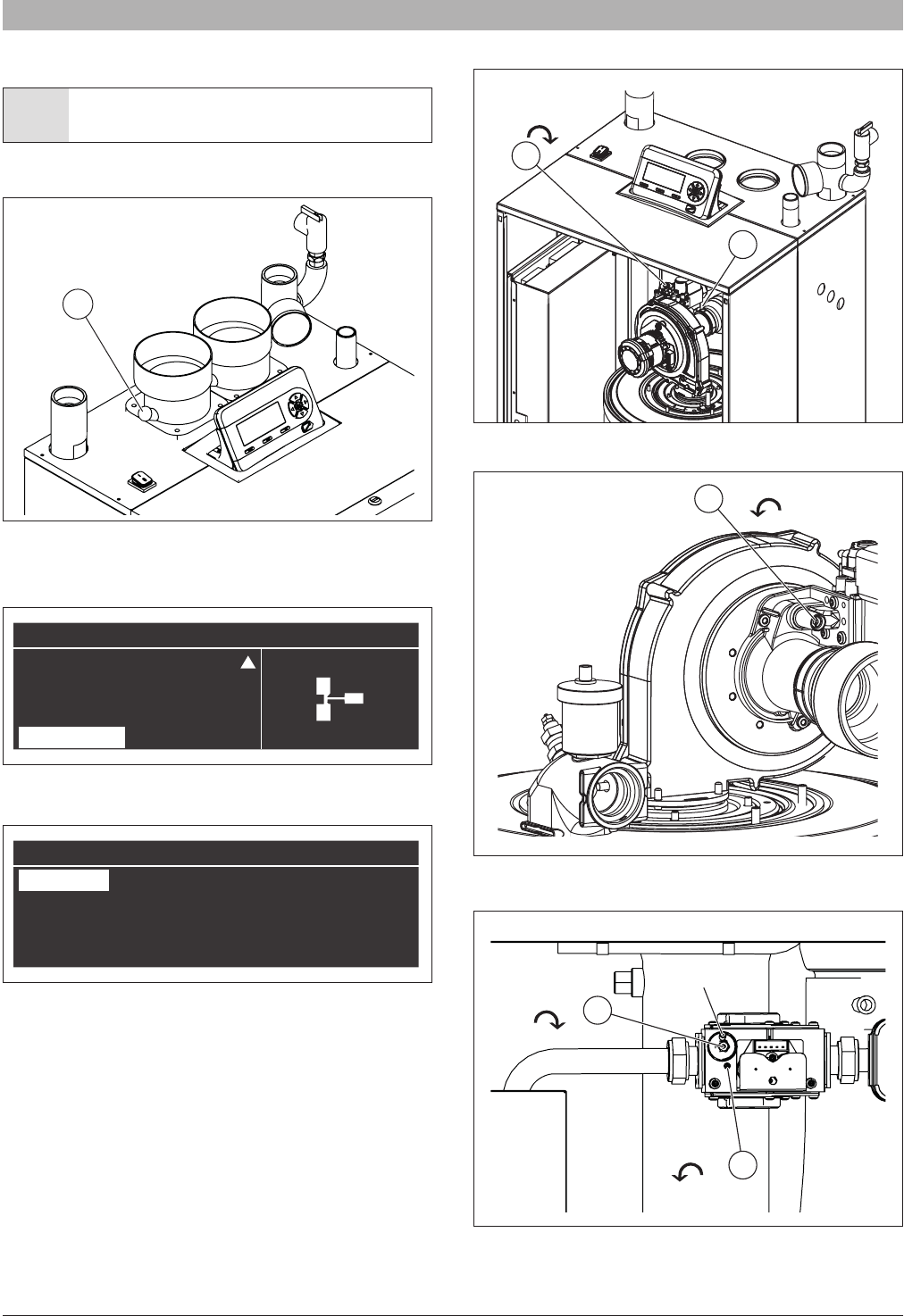
Insert a combustion analyzer probe into the test port “A” as shown in Fig.
67.
Fig. 67
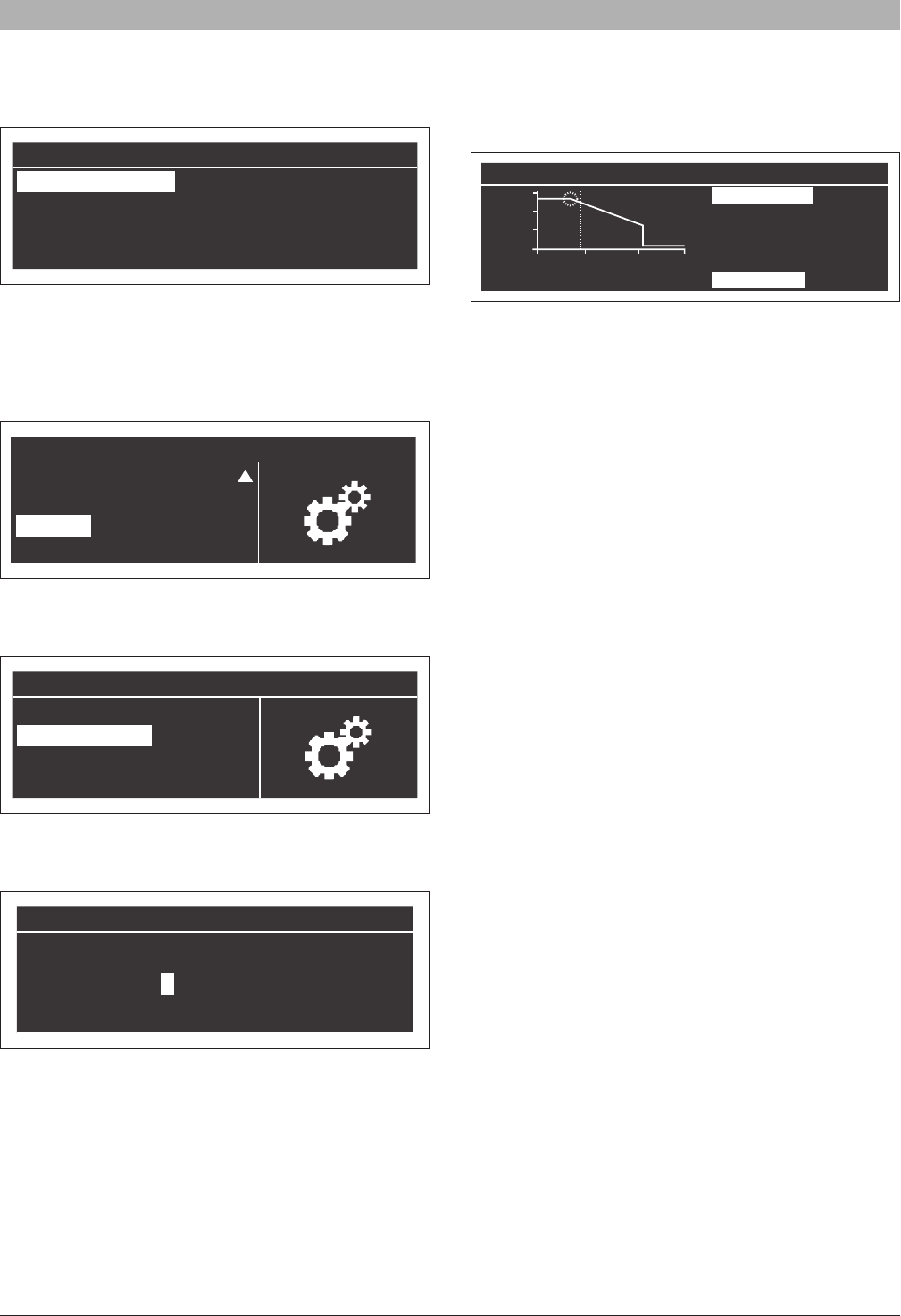
►Press “Menu” key.
►Select “System Test”:
►In “System test” menu select “High Power” using “Up/Down” keys and
press “OK”:
ù
e “Test Status” switches to “on” and in the display will appear the fan speed. Wait 2 or 3 minutes to to reach steady state conditions and record the CO2 value.
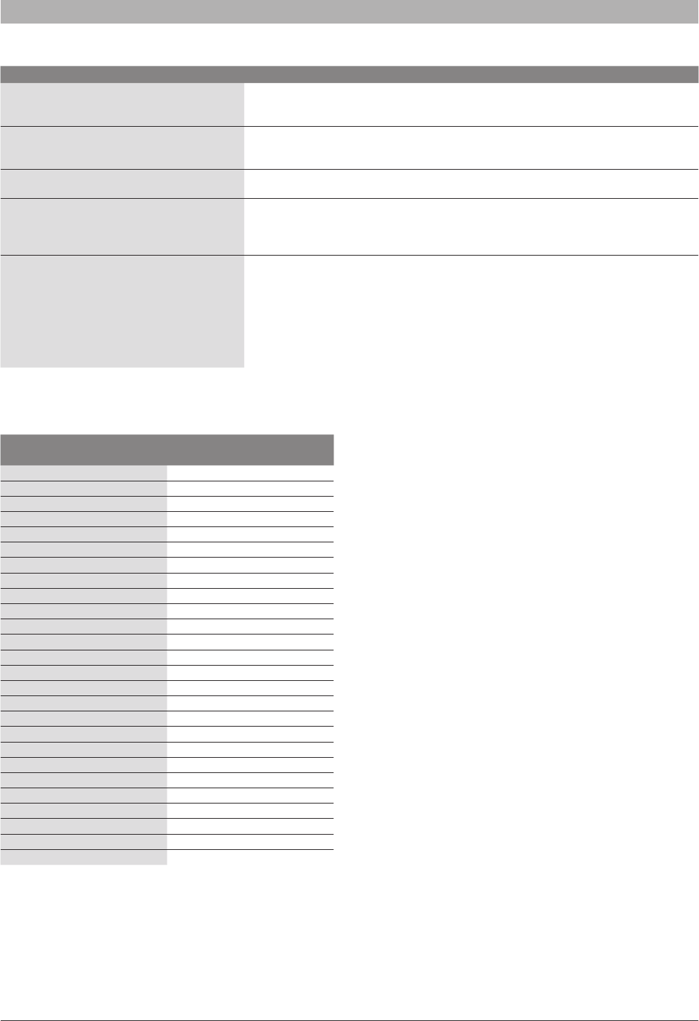
To adjust the CO2 value at the maximum power turn the screw “A” shown
in Fig. 69 (for SSB255) and in Fig. 70 (for SSB399 and SSB512), allen
type wrench is necessary for this adjustment.
Fig. 68 Gas valve screw regulation for SSB255
Fig. 69 Gas valve screw regulation for SSB255
Fig. 70 Gas valve screw regulation for SSB399 and SSB512
(*) Balancing tube shown removed for clarity.
A
Menu
Domestic Hot Water
Information
Settings
System Test
System Test
Test StateHigh Power
Fan Speed0 rpm
Ionisation0.0 μA
A
CO2 +
B
A
CO2 +
A
CO2 +
CO2 +
CO2 +
B
A
(*)
6720818454 (2016/02) USSSB
40 | Troubleshooting
Verify that the value of CO2 is stable and is within the range indicated in
the following table (be careful to make small changes and conrm that the
value is stable before making additional adjustment).
Select “Low Power” using “UP/Down” button and press “OK”:
The fan will run at the minimum speed.
To adjust the CO2 value at the minimum power turn the screw “B” shown
in Fig. 68 and in Fig. 70.
Verify that the value of CO2 is stable and is within the range indicated in
the following table (be careful to make small changes and conrm that the
value is stable before making additional adjustment).
Select “OFF” using “UP/Down” button and press “OK”:
The “Test State” switches to OFF and the boiler return to the “stand by”
mode.
Gas TypeMax. power CO2%Min. power CO2%
Natural gas8.8-9.28.8-9.2
LP gas10.3-10.710.3-10.7
Tab. 16 CO2 value for gas valve calibration
Tab. 17 indicates the approximate number of turns required to start the
boiler when when LPG conversion kit has been installed. [refer to section
4.6.2 for NG to LPG conversion instructions].
The number of turns has been counted from when the maximum and
minimum adjustment has been wound fully closed.
This procedure is not applicable to the minimum setting of SSB399 and
SSB512 valve [see Tab. 17].
These are approximate gures for LPG gas appliances. A combustion
analyzer must be used to set maximum and minimum CO2 as listed in
table Tab. 16.
Appliance
Maximum settingMinimum setting
Number of turns from gas
valve fully wound home
Number of turns from gas
valve fully wound home
SSB25510 turns2 and ¼ turns
SSB3997 turnsNA
SSB5127 turnsNA
Tab. 17 Number of turns for gas valve settings
5.8 Setting frost protection
The boiler is equipped with a system frost protection function, see section
“5.5 Parameters list” for a list of all parameters and settings.
The factory default setting Frost Protection (parameter # 89) is
“DISABLED”. To enable frost protection simply adjust parameter # 89 to
“ENABLE”. When the frost protection is enabled, Parameter #90 (Frost
Protection Setpoint) has to be set. Parameter #90 has a default setting of
50°F and can be adjusted from 33-68 °F.
When the supply temperature falls below the value set by the parameter
#90, the boiler pump starts.
If the supply temperature continues to fall and reaches 9 °F (5 °C) below the
value set by the parameter #90 the burner will switch on at minimum power.
When the supply temperature increases to a temperature of 9 °F (5°C)
greater than the value of the parameter # 90 the burner will switch off.
Then after the post circulation time has elapsed the pump will stop
(parameter #5 adjustable from 300-900 seconds. Default is 300 seconds).
For example, parameter #90 is set at 50 °F (10 °C), when the Supply
temperature is lower than 50 °F (10 °C) the pump starts. If the supply
temperature is lower than 41 °F (5 °C) the burner starts at the minimum power.
The burner switches off when a temperature of 59 °F (15 °C) is achieved.
NOTICE: This sequence protects the boiler only from
freezing. Be sure adequate measures are in place to protect
the system.
6 Troubleshooting
WARNING: Close the gas cock prior to working on the gas
train or “boiler”.
WARNING: Check for gas leaks after carrying out work on
the gas train.
WARNING: Check for leaks after carrying out work on the
venting system.
DANGER: Always disconnect the appliance from the
main power before performing any work. Disconnect the
emergency shutoff switch or disengage the heating system
circuit breaker. Take measures to prevent accidental
reconnection.
WARNING: Hot water can scald. Drain the appliance before
working on components that are lled with water.
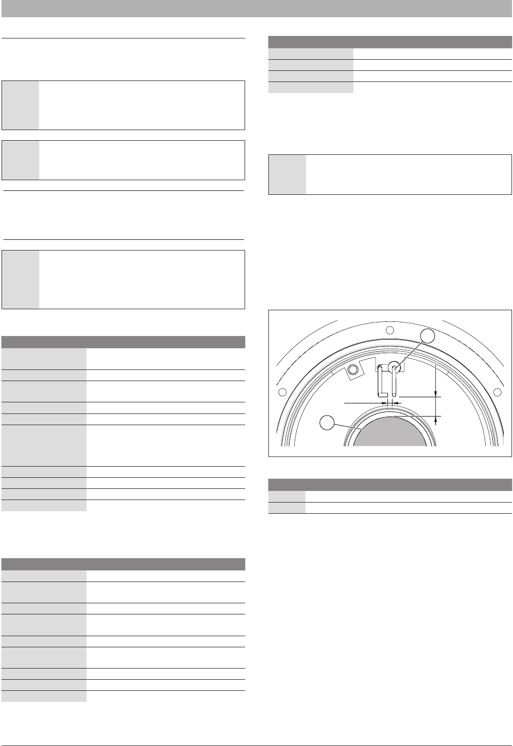
6.1 Error codes are shown on the display
If the symbol appears on the screen as follow:
Fig. 71
an error has occurred in the system that is displayed on the screen. The
bottom row in the display will show the description of the error occurred.
System Test
Test StateLow Power
Fan Speed0 rpm
Ionisation0.0 μA
System Test
Test StateOff
Fan Speed0 rpm
Ionisation0.0 μA
04:29 pm
70.0°F
SSB6720818454 (2016/02) US
Troubleshooting | 41
6.1.1 Lockout errors
If an error is a “Lockout” error, it is necessary to press “RESET” button (after eliminating the reason for the failure) to restart the boiler.
In the following table the “Lockout” errors are listed:
ErrorInt. nr.DescriptionChecksSolutions
"Ignit Error"1
Three unsuccessful ignition attempts in
a row
a- Check gas supply
pressure;
b- Check ignition spark
c- Correct amount of gas;
d-Check for120VAC at the
gas valve;
a- If the gas supply pressure is
incorrect, it must be adjusted to the
correct pressure;
b- If spark is not present check for
correct ignition electrode position;
c- If the combustion air pressure is
incorrect, inspect the vent system
and eliminate any obstructions;
d- If the voltage to the gas valve is
not 120Vac the power control board
must be replaced.
"Gv Relay Error"2
Failure detected in the GV (gas valve)
Relay
a- Check the integrity of the
wire connections between
gas valve and control board.
a- If wires are damaged, replace
them
b- If wires are ok, replace the gas
valve or the power control board.
"Gv Relay Not Open"3
Failure detected in the GV (gas valve)
Relay
a- Check the integrity of the
wire connections between
gas valve and control board.
a- If wires are damaged, replace
them;
b- If wires are ok, replace the gas
valve or the power control board.
"Gv Relay Not Close"4
Failure detected in the GV (gas valve)
Relay
a- Check the integrity of the
wire connections between
gas valve and control board.
a- If wires are damaged, replace
them;
b- If wires are ok, replace the gas
valve or the power control board.
"Safety Relay Error"5Failure detected in the Safety RelayReplace the power control board
"Safety Relay Open"6Failure detected in the Safety RelayReplace the power control board
"Safety Relay Closed"7Failure detected in the Safety RelayReplace the power control board
"Blocking Too Long Error"11
Control had a blocking error for more
than 20 hours in a row
Press RESET button to
display the Blocking error
description
Remove the cause of the Blocking
error
"Fan Error"12Fan MF deviation for more than 60 sec
a- Check for 120 Vac power
connection of the fan.
b- Check PWM connection of
the fan.
a- If no 120 VAC voltage is present,
replace the power control board.
b- If no PWM signal is present,
replace power control board.
c- Replace the fan
"Ram Error"13Internal software errorReplace the power control board
"Wrong E2prom Signature"14Contents of E2prom is not up-to-dateReplace the power control board
"X Ram Error"15Internal software errorReplace the power control board
"E2Prom Error"16No communication with E2promReplace the power control board
"E2Prom Error C"17Wrong safety parameters in E2promReplace the power control board
"E2Prom Error Cal Table"18Wrong calibtration table parametersReplace the power control board
"State Error"19Internal software errorReplace the power control board
"Rom Error"20Internal software errorReplace the power control board
"Rom Error C"21Internal software errorReplace the power control board
"Air Sw Not Open"22Air pressure switch not working
"15Ms Xrl Error"23Internal software errorReplace the power control board
"Air Sw Not Closed"24Air pressure switch not working
“Max. Thermostat Lock Error”25
The external overheat protection is
activated
a- Check the pump to verify
the ow circulation
b- Check if the valves on
hydraulic circuit are open
c- Check the high limit switch
d- To reset - see “Fig. 10”,
section 4.4.2
a- Change the pump or restart it
b- Open the valves on hydraulic
circuit
c- Change the high limit switch
"Stack Error"26Internal errorReplace the power control board
"Flame Out Too Late Error"27
Flame still present 10 sec. after closing
the gas valve
Replace the gas valve
"Flame Error 1"28Flame is detected before ignitionReplace the gas valve
"20Ms Xrl Error"29Internal software errorReplace the power control board
"41Ms Error"30Internal software errorReplace the power control board
Tab. 18 Lockout codes
6720818454 (2016/02) USSSB
42 | Troubleshooting
ErrorInt. nr.DescriptionChecksSolutions
"Too Many Flame Failures"31
Three times ame lost during one
demand
a- Check the integrity of
the wire connections of the
spark and the earth on heat
exchanger
a- If wires are damaged, replace
them
"Flow Switch Not Closed Error" 32Flow switch not working / No ow
"Flow Switch Not Open Error" 33Flow switch not working / No ow
"Flag Byte Integrity Error"34Internal software errorReplace the power control board
"Ad Hi Cpl Error"35Internal software errorReplace the power control board
"Ad Lo Cpl Error"36Internal software errorReplace the power control board
"Register Error"37Internal software errorReplace the power control board
Tab. 18 Lockout codes
6.1.2 Blocking errors
If it is “Blocking” error the boiler will go back to normal operation, with no need to press the “RESET” button, once the reason for the failure has been
eliminated.
In the following table the “Blocking” errors are listed:
ErrorInt. nr.DescriptionChecksSolutions
"WD Error Ram"45Internal software errorReplace the power control board
"WD Error Rom"46Internal software errorReplace the power control board
"WD Error Stack"47Internal software errorReplace the power control board
"WD Error Register"48Internal software errorReplace the power control board
"WD Error Xrl"49Internal software errorReplace the power control board
"Refhi Too Lo Error"50Internal software errorReplace the power control board
"Refhi Too Hi Error"51Internal software errorReplace the power control board
"Reo Too Lo Error"52Internal software errorReplace the power control board
"Reo Too Hi Error"53Internal software errorReplace the power control board
"Flame Error 2"54
Flame is detected in a state in which no
ame is allowed to be seen
Replace the power control board
"Water Level Detect"55Low water level detected
"Water Level Meas"56Low water level measurement error
"Low Water Cutoff Error"57Low water sensor errorCheck the LWCO
If the LWCO is in alarm, try to reset
it.
"Low Water Pressure Error"58Low water pressure error
"Low Water Pressure Sensor"59Low water pressure
"Flue Gas Error"60Flue gas pressure error
a- Check the ue gas
pressure switches
b- Check the gas pressure
a- If the ue gas pressure switches
don’t work, replace them
b- If the gas supply pressure is
incorrect, it must be adjusted to the
correct pressure pressure
"Return Temp Error"61
Return temperature is higher than stay
burning temperature
a- Check the return
temperature sensor
b- Verify the pump for ow
circulation
a- Verify that the temperature
sensor has the correct resistance
values. If values are incorrect
sensor must be replaced.
b- Change the pump or restart it
"Blocked Drain Error"62Block drain switch is active
"Wd Freq Error"64
Incorrect Frequency signal or no
communication with the WD
Verify the supplied 120 V ac
current
a- If the supplied 120 V ac current
has a frequency of 60HZ +/- 2% ,
replace the power control board
b- If the frequency is out of range,
consult electrician
"Phase Error"65Hot neutral reversed
Check the supply 120 V ac
connection
Reverse the supply voltage polarity
"Net Freq Error"66Net freq. error detected in the main
Check the frequency of the
supply 120 V ac connection
a- If the supplied 120 V ac current
has a frequency of 60HZ +/- 2% ,
replace the power control board
b- If the frequency is out of range,
consult electrician
"Faulty Earth Error"67Faulty earth connection
Check the earth connection
to the appliance
Restore the earth connection
"WD Communication Error"68Watchdog communication errorReplace the power control board
Tab. 19 Blocking errors
SSB6720818454 (2016/02) US
Troubleshooting | 43
ErrorInt. nr.DescriptionChecksSolutions
“Overheat Error”70Supply temp exceed the limit
a- Check the pump to verify
the ow circulation
b- Check if the valves on
hydraulic circuit are open
c- Check the supply
temperature sensor
a- Change the pump or restart it
b- Open the valves on hydraulic
circuit
c- Verify that the temperature sensor
has the correct resistance values. If
values are incorrect sensor must be
replaced.
"T Supply Open"72Supply sensor open
a- Check the integrity of the
wire connections
b- Check the supply
temperature sensor
a- If the wiring is damaged, replace
it
b- Verify that the temperature
sensor has the correct resistance
values. If values are incorrect
sensor must be replaced.
"T Return Open"73Return sensor open
a- Check the integrity of the
wire connections
b- Check the return
temperature sensor
a- If the wiring is damaged, replace
it
b- Verify that the temperature
sensor has the correct resistance
values. If values are incorrect
sensor must be replaced.
"T Dhw Out Open"76DHW sensor open
a- Check the integrity of the
wire connections
b- Check the DHW
temperature sensor
a- If the wiring is damaged, replace
it
b- Verify that the temperature
sensor has the correct resistance
values. If values are incorrect
sensor must be replaced.
"T Supply Shorted"80Supply sensor shorted
a- Check the integrity of the
wire connections
b- Check the supply
temperature sensor
a- If the wiring is damaged, replace
it
b- Verify that the temperature
sensor has the correct resistance
values. If values are incorrect
sensor must be replaced.
"T Return Shorted"81Return sensor shorted
a- Check the integrity of the
wire connections
b- Check the return
temperature sensor
a- If the wiring is damaged, replace
it
b- Verify that the temperature
sensor has the correct resistance
values. If values are incorrect
sensor must be replaced.
"T Dhw Out Shorted"84DHW sensor shorted
a- Check the integrity of the
wire connections
b- Check the DHW
temperature sensor
a- If the wiring is damaged, replace
it
b- Verify that the temperature
sensor has the correct resistance
values. If values are incorrect
sensor must be replaced.
"T Flue Shorted"86Flue sensor shorted
a- Check the integrity of the
wire connections
b- Check the ue temperature
sensor
a- If the wiring is damaged, replace
it
b- Verify that the temperature
sensor has the correct resistance
values. If values are incorrect
sensor must be replaced.
"Reset Button Error"87Reset button error
Too many reset button
pushes in a 60 sec period
"Appliance Selection"93Appliance selection errorReplace the power control board
"Gas Pressure Error"107Gas pressure too low or too high
"Flue Press Error"108Flue gas pressure error
a- Check for any obstruction
in the exhaust system
b- Check the condensate
discharge
a- Remove any obstructions from
the exhaust system
b- Remove any obstruction from
condensate discharge and verify if
the condensate can ow freely
Tab. 19 Blocking errors
6720818454 (2016/02) USSSB
44 | Troubleshooting
6.2 Errors not shown on display
SymptomsPossible solutions
Combustion noise too loud; rumbling noises
Check gas type.
Check inlet gas pressure; adjust as needed. Check ue gas system; clean or repair as needed.
Check gas/air ratio in the combustion air and ue gas; replace gas valve as needed.
Flow noises
Set pump speed correctly to match maximum output.
Set pump mode.
Purge system.
Heating-up takes too long
Set pump speed correctly to match maximum output.
Set pump mode.
Flue gas readings incorrect; CO levels too high
Check gas type.
Check inlet gas pressure; adjust as needed.
Check ue gas system; clean or repair as needed.
Check gas/air ratio in ue gas; replace gas valve as needed.
Hard ignition, poor ignition
Check gas type.
Check inlet gas pressure; adjust as needed.
Check power supply.
Check electrodes for visual damage; replace as needed.
Check ue gas system; clean or repair as needed.
Check gas/air ratio; replace gas valve as needed.
Check gas valve; replace as needed.
Check burner; replace if required.
Tab. 20
6.3 Sensor Resistance table
Temperature °F (°C)
Testing tolerance ±10%
Resistance [Ω]
32 (0)27396
41 (5)22140
50 (10)17999
59 (15)14716
68 (20)12099
77 (25)10000
86 (30)8308
95 (35)6936
104 (40)5819
113 (45)4904
122 (50)4151
131 (55)3529
140 (60)3012
149 (65)2582
158 (70)2221
167 (75)1918
176 (80)1663
185 (85)1446
194 (90)1262
203 (95)1105
212 (100)970
221 (105)855
230 (110)755
239 (115)669
248 (120)594
257 (125)529
Tab. 21 Resistance table for: Supply temperature sensor, Return
sensor, Flue sensor, DHW tank temperature sensor, LLH
sensor, Outdoor temperature sensor
SSB6720818454 (2016/02) US
Maintenance | 45
7 Maintenance
7.1 General
NOTICE: The installer must inform the user about the
contents of this section. The user must make the necessary
arrangements with qualied service agency for the care and
periodic maintenance of the boiler.
CAUTION: Lack of care and maintenance of this boiler and
equipment may cause an unsafe condition.
A qualied and adequately trained technician must perform
the inspection as specied in these instructions and in the
Service Manual (provided separately) before each heating
season and at regular intervals.
WARNING: Servicing, inspection and adjustment must
be done by a trained technician in accordance with all
applicable local and national codes. Improper servicing or
adjustment could damage the boiler and result in equipment
damage or a dangerous condition!
7.2 Maintenance / inspection schedule for end user
Time intervalMaintenance
Annually
Verify the cleanliness of the area around the
boiler
AnnuallyCheck the pressure of the hydraulic system
Annually
Check vent piping and verify if leaks are
present
AnnuallyCheck air piping and verify if leaks are present
AnnuallyCheck relief valve
Monthly (follow local,
state, federal or local
authority having
jurisdiction guidelines)
Verify the condensate discharge system
Every two monthsTest low water cut off
Every two monthsVerify the reset button of low water cut off
Every six monthsCheck all piping (gas and water) for leaks
End of heating seasonShut off the boiler
Tab. 22 User maintenance / inspection schedule
7.3 Maintenance / inspection schedule for licensed
contractor / gas tter
Time intervalMaintenance
Annually *Combustion test
Annually *
Verify condition of ue and air system
(including Venturi and fan)
Annually *Check ignition electrode
Annually *
Cleaning the combustion chamber (including
the burner tube)
Annually *Clean condensate discharge
Annually *
Safety block check, modulation range check,
gas valve closing after burner stop
Annually *Check control parameters
Annually *Check for gas piping leak
Annually *Check wiring and connection
(*) Annually or every 2000 hours. Which occurs rst.
� Documented the modied setting of the heating control in the control operating/ installation instructions
The following work has been carried out:
� Electrical connections checked, notes:
� Condensate trap lled� Carry out a combustion air/ue gas test
� Function check carried out � Tightness test carried out on the gas and water sides
Commissioning includes checking the setting, a visual heating leak test and a functional check oh the boiler and control. The system installer conducts a
test of the heating system.
This system has been checked to the extent described.The documents have been handed over to the home owner/operator. The
home owner/operator has been instructed regarding safety and operation
of the boiler and accessories, including the need for regular scheduled
maintenance.
Name of service installing contractorDate, owner/operator signature
Afx the test report here.
Date, system installer’s signature
6720818454 (2016/02) USSSB
56 | Spare parts
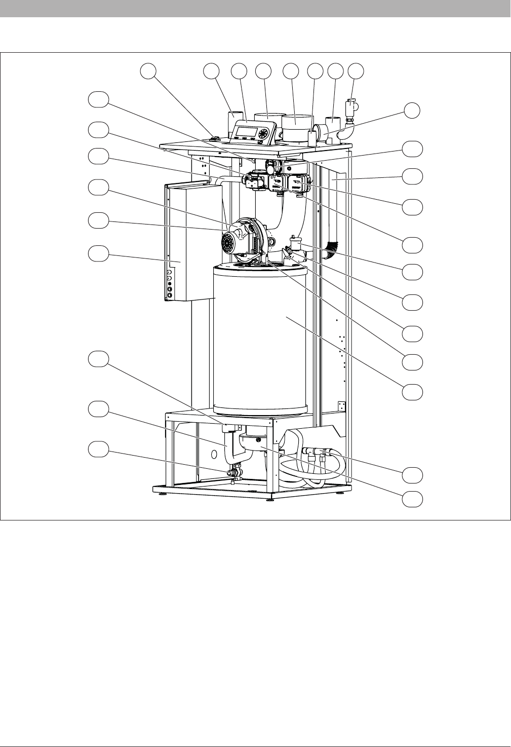
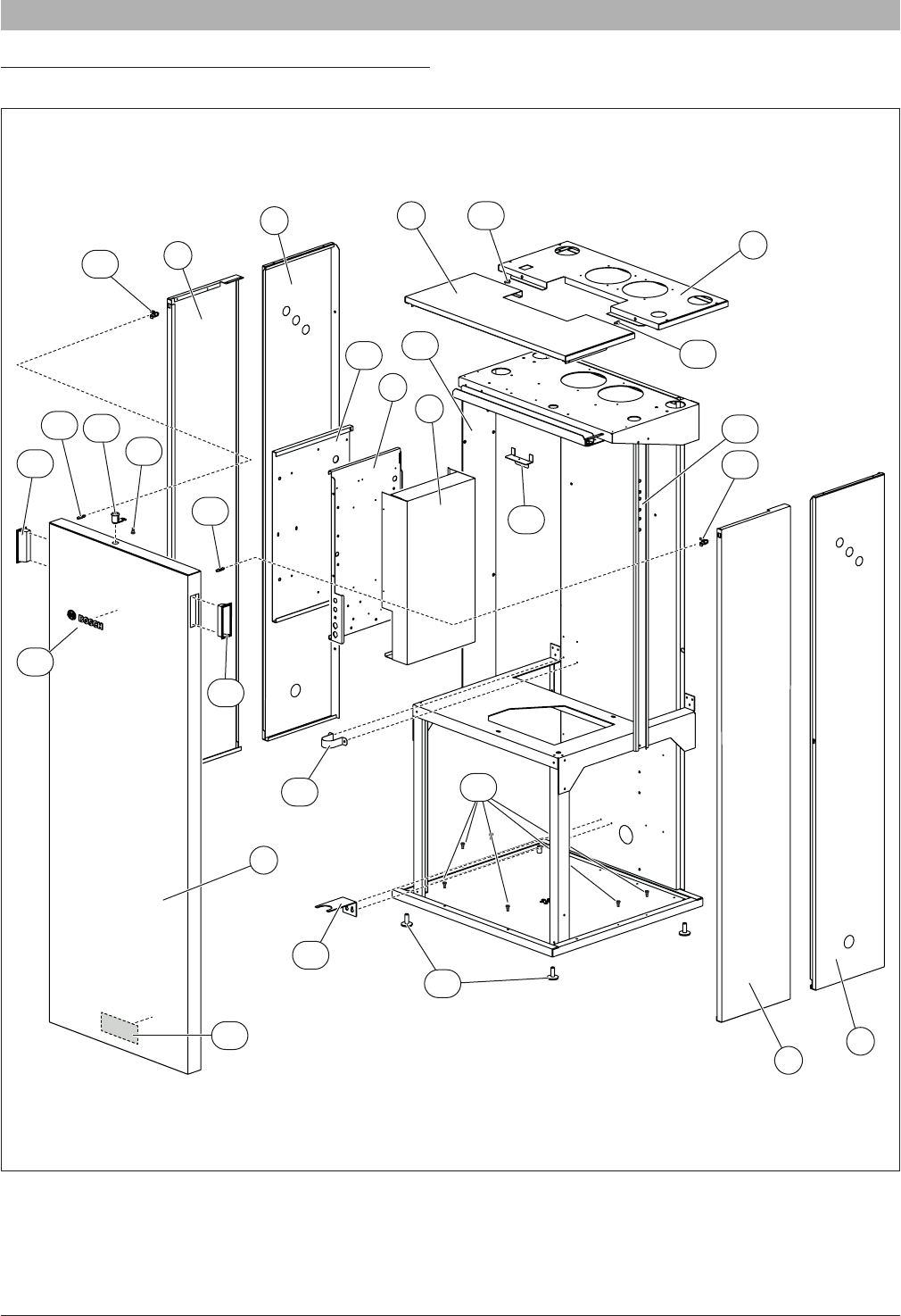
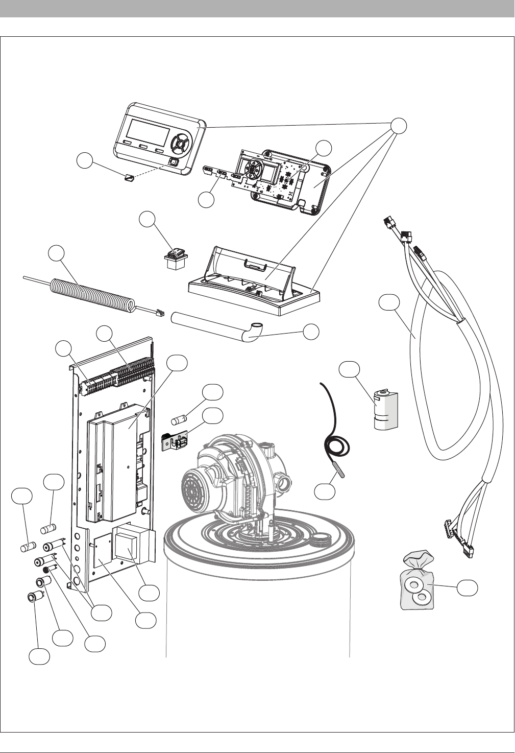
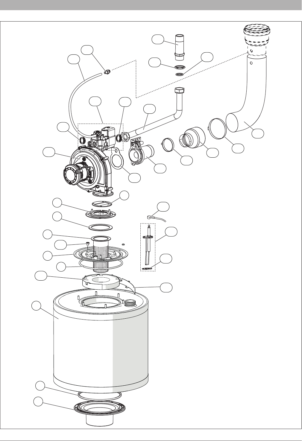
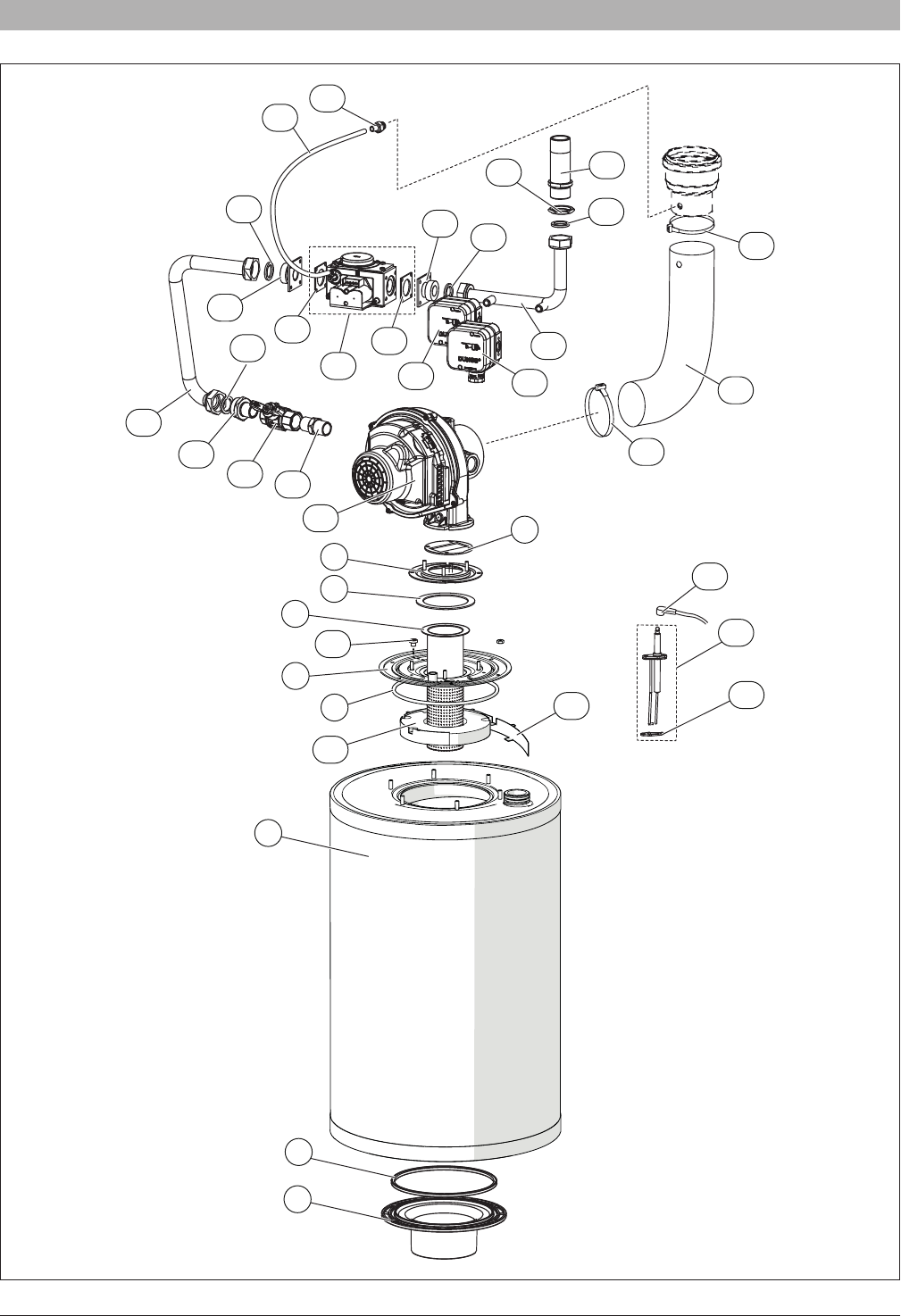
10 Spare parts
Fig. 82
1
2
4
8
9
3
5
6
7
17
24
18
19
17
20
12
13
10
14
15
16
21
23
19
23
22
22
11
25
SSB6720818454 (2016/02) US
Spare parts | 57
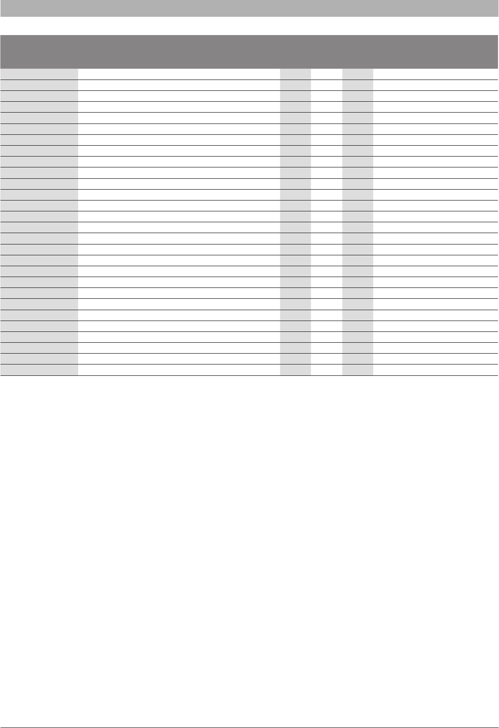
Item (→ Fig. 82)Description
SSB255
SSB399
SSB512
Order number
1Panel front■■■7-738-004-899
2Panel left side front■■■7-738-004-900
3Panel right side front■■■7-738-004-901
4Panel left side rear■■■7-738-004-902
5Panel right side rear■■■7-738-004-903
6Panel top front■■■7-738-004-904
7Panel top rear■7-738-004-906
7Panel top rear■■7-738-004-905
8Cover control board■■■7-738-004-907
9Mounting bracket control board panel ■■■7-738-004-908
Gebruikershandleiding.com neemt misbruik van zijn services uitermate serieus. U kunt hieronder aangeven waarom deze vraag ongepast is. Wij controleren de vraag en zonodig wordt deze verwijderd.
Product:
Spelregels forum
Om tot zinvolle vragen te komen hanteren wij de volgende spelregels:
lees eerst de handleiding door;
controleer of uw vraag al eerder door iemand anders is gesteld;
probeer uw vraag zo duidelijk mogelijk te stellen;
heeft u een probleem en al geprobeerd om dit op te lossen, vermeld dit erbij aub;
heeft u een oplossing gekregen van een bezoeker dan horen wij dat graag in dit forum;
wilt u een reactie geven op een vraag of antwoord, gebruik dan niet dit formulier maar klik op de knop 'reageer op deze vraag';
uw vraag wordt direct op de website gezet; vermijd daarom persoonlijke gegevens in te vullen;
Belangrijk! Als er een antwoord wordt gegeven op uw vraag, dan is het voor de gever van het antwoord nuttig om te weten als u er wel (of niet) mee geholpen bent! Wij vragen u dus ook te reageren op een antwoord.
Belangrijk! Antwoorden worden ook per e-mail naar abonnees gestuurd. Laat uw emailadres achter op deze site, zodat u op de hoogte blijft. U krijgt dan ook andere vragen en antwoorden te zien.
Abonneren
Abonneer u voor het ontvangen van emails voor uw Buderus SSB512 bij:
nieuwe vragen en antwoorden
nieuwe handleidingen
U ontvangt een email met instructies om u voor één of beide opties in te schrijven.
Ontvang uw handleiding per email
Vul uw emailadres in en ontvang de handleiding van Buderus SSB512 in de taal/talen: Engels als bijlage per email.
De handleiding is 9,92 mb groot.
U ontvangt de handleiding per email binnen enkele minuten. Als u geen email heeft ontvangen, dan heeft u waarschijnlijk een verkeerd emailadres ingevuld of is uw mailbox te vol. Daarnaast kan het zijn dat uw internetprovider een maximum heeft aan de grootte per email. Omdat hier een handleiding wordt meegestuurd, kan het voorkomen dat de email groter is dan toegestaan bij uw provider.
Uw handleiding is per email verstuurd. Controleer uw email
Als u niet binnen een kwartier uw email met handleiding ontvangen heeft, kan het zijn dat u een verkeerd emailadres heeft ingevuld of dat uw emailprovider een maximum grootte per email heeft ingesteld die kleiner is dan de grootte van de handleiding.
Er is een email naar u verstuurd om uw inschrijving definitief te maken.
Controleer uw email en volg de aanwijzingen op om uw inschrijving definitief te maken
U heeft geen emailadres opgegeven
Als u de handleiding per email wilt ontvangen, vul dan een geldig emailadres in.
Uw vraag is op deze pagina toegevoegd
Wilt u een email ontvangen bij een antwoord en/of nieuwe vragen? Vul dan hier uw emailadres in.