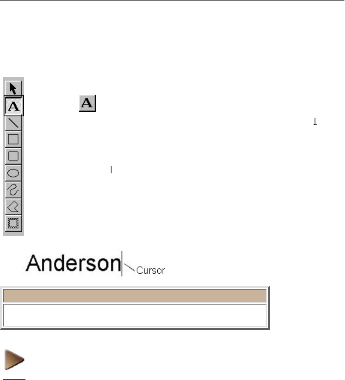
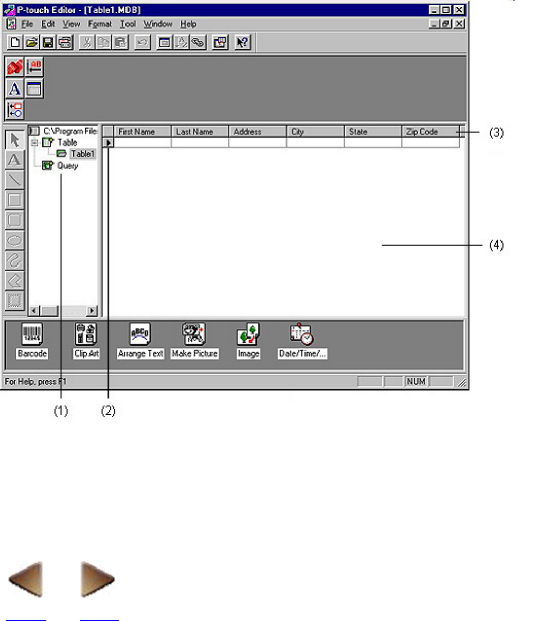
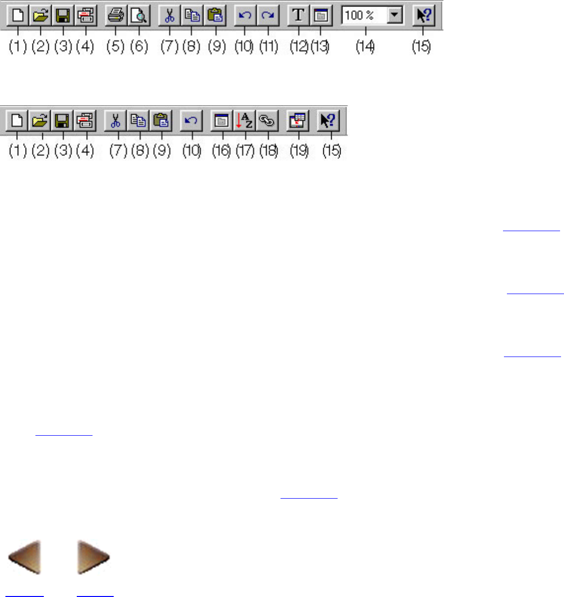
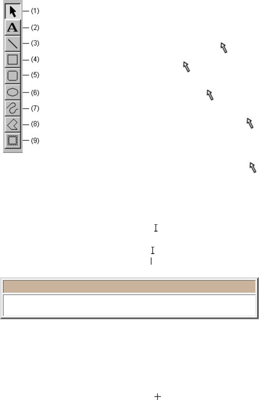
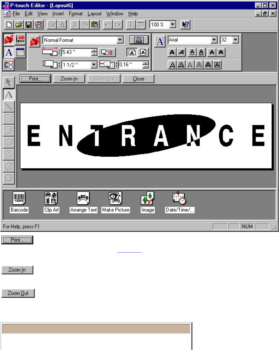
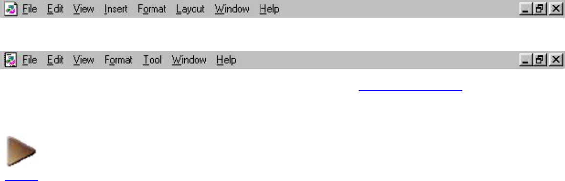
Draw toolbar
The draw toolbar contains a selection of buttons necessary for selecting objects
and for drawing any shape.
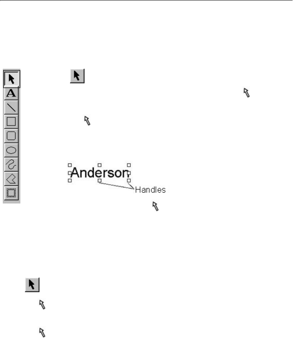
(1) [Select] button
Click this button to change the pointer to
.●
To select an object, move the pointer on top of the object, then click the
left mouse button.
●
To move a selected object, move the pointer on top of the object, then
hold down the left mouse button and drag the mouse.
●
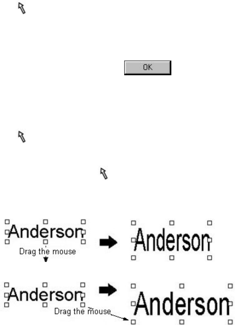
To change the size of a selected object, move the pointer over one of
the handles around the object, then hold down the left mouse button and
drag the mouse.
●
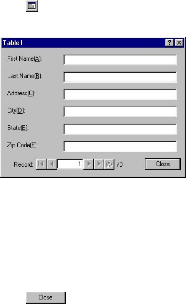
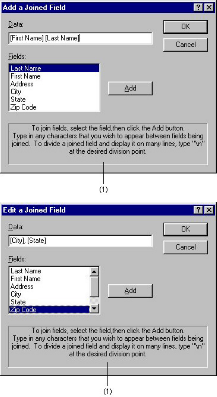
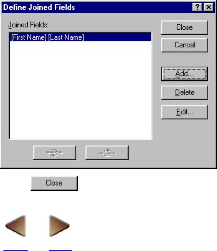
To display a dialog box which can be used to edit an object, move the pointer on top of the
object, then double-click the left mouse button. The dialog box can also be displayed by
selecting an object, then clicking the right mouse button and selecting the [Properties]
command from the pop-up menu.
●
(2) [Text] button
Click this button to change the pointer to
(the I-beam pointer) when it is moved into the layout
area.
●
To create a new text object, position the pointer at the desired position in the layout area, then
click the left mouse button. The cursor (
) flashes in the layout area to indicate that you can
now type in text.
●
Note:
Text is always typed in using the insert mode. You cannot use the insert key
on your computer keyboard to switch to the overwrite mode.
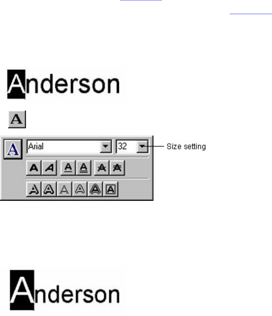
To edit existing text, move the text cursor to the beginning of the text to be edited and while
holding down the left mouse button, drag the mouse to highlight the text. You can now edit the
highlighted text or change its font, size, or other attributes.
●
When a new text object is created, the size of the object automatically adjusts to fit the text.●
If you delete all text contained in a text object, the object itself disappears.●
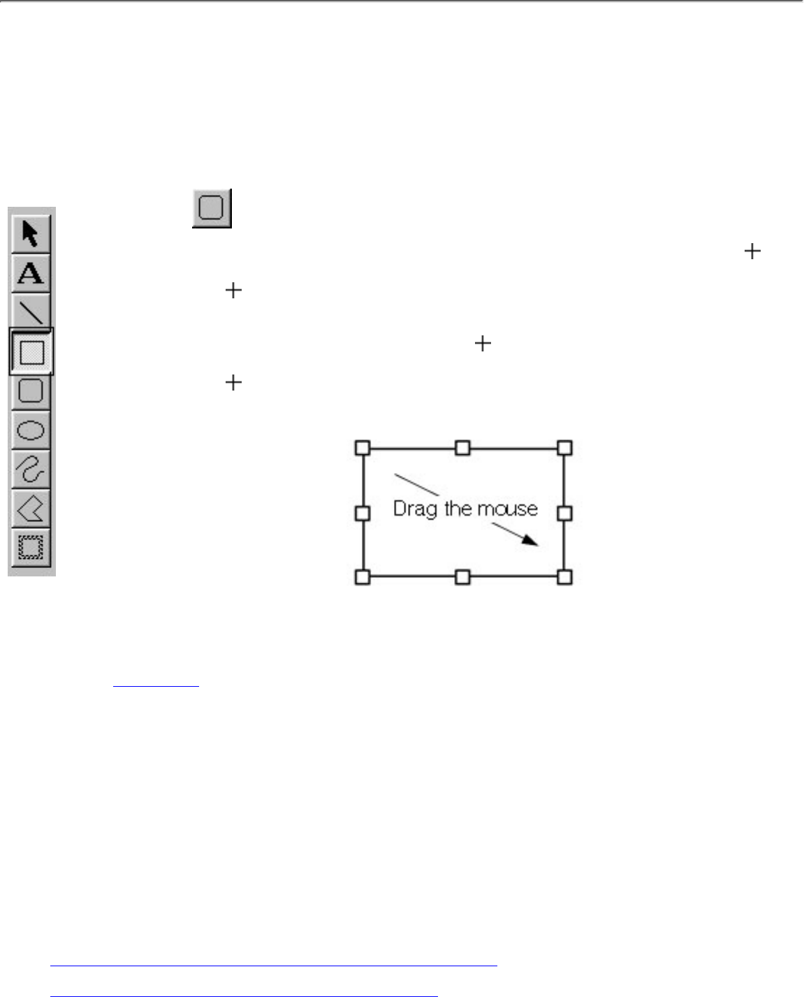
(3) [Line] button
Click this button to change the pointer to
when it is moved into the layout area.●
To draw a straight line, hold down the left mouse button and drag the mouse. Then, release the
mouse button at the end of the line.
●