Before Starting Operation...............................................................................................................................................8
Procedure of Reading This Manual..............................................................................................................................10
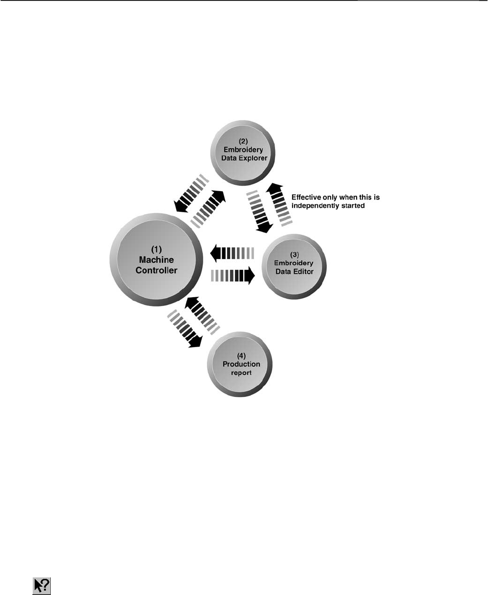
2-2 Configuration of Software...................................................................................................................................1-4
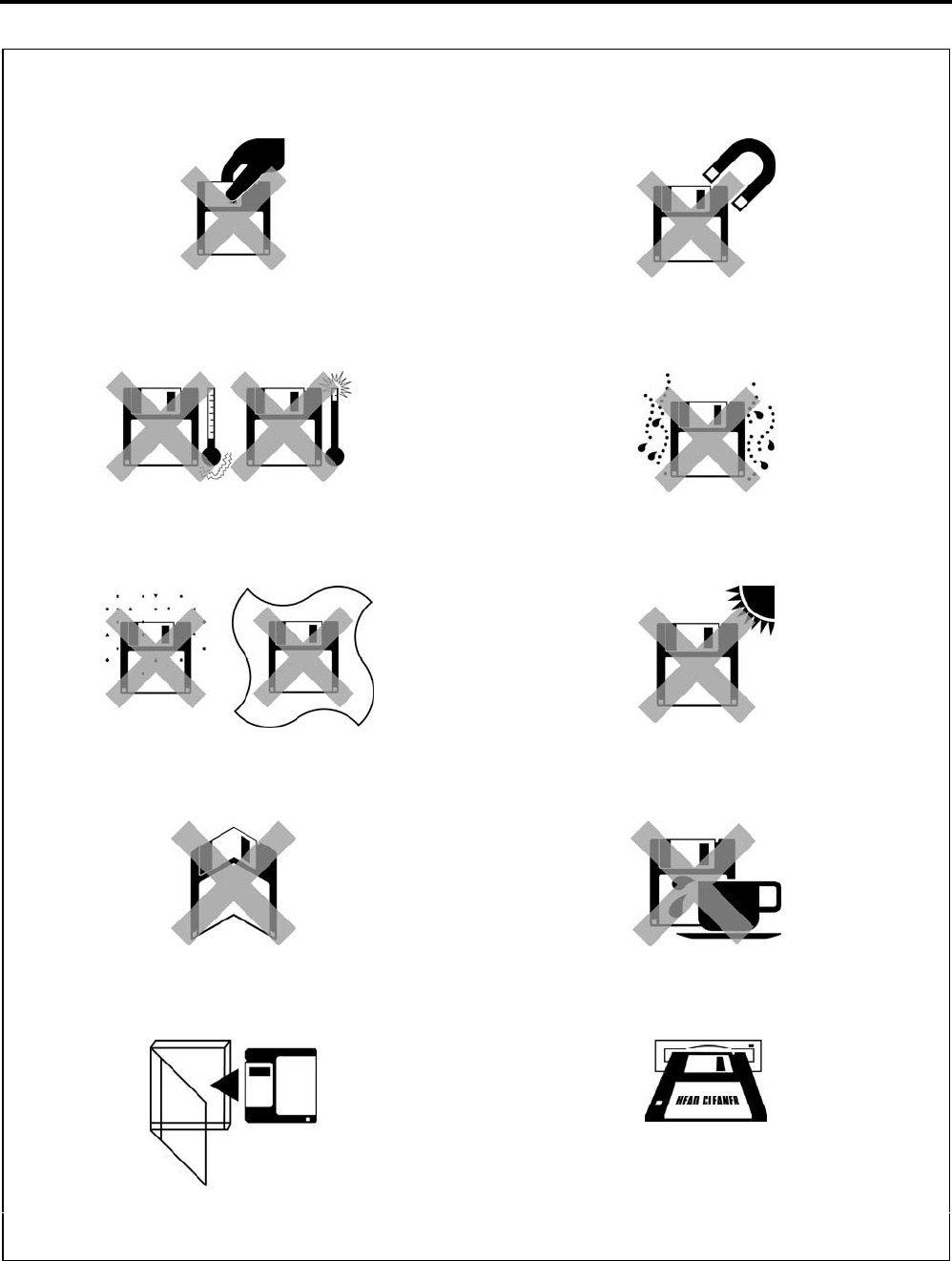
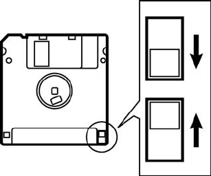
2-3 Notes on use......................................................................................................................................................1-5
2-5 Basic Operation of Software..............................................................................................................................1-6
Chapter 2 Preparation of Embroidery Machine
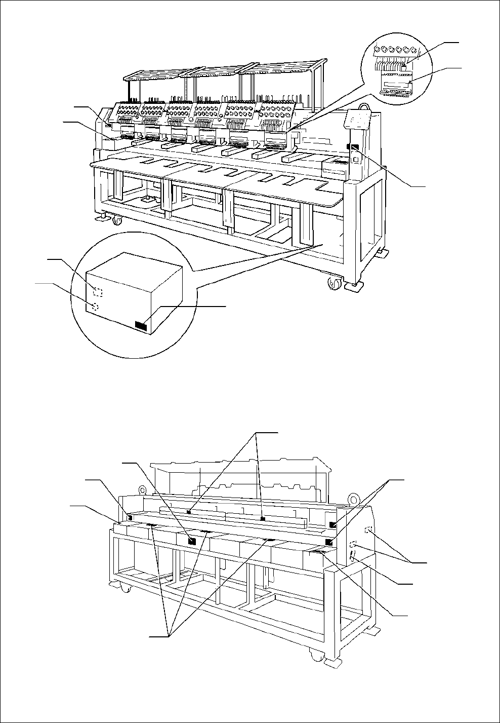
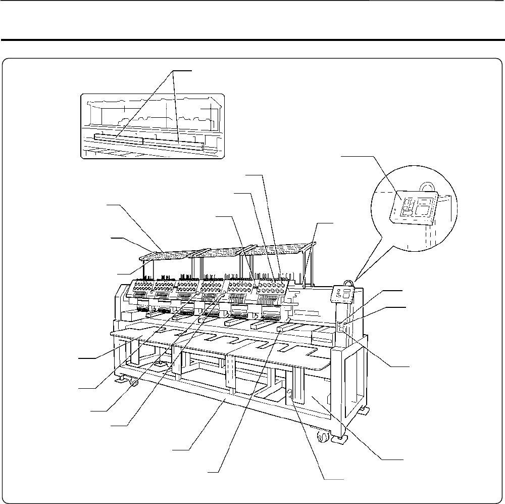
1. Names of Machine Components..............................................................................................................................2-2
2-1 Transportation of Machine..................................................................................................................................2-3
2-2 Installation of Machine.......................................................................................................................................2-5
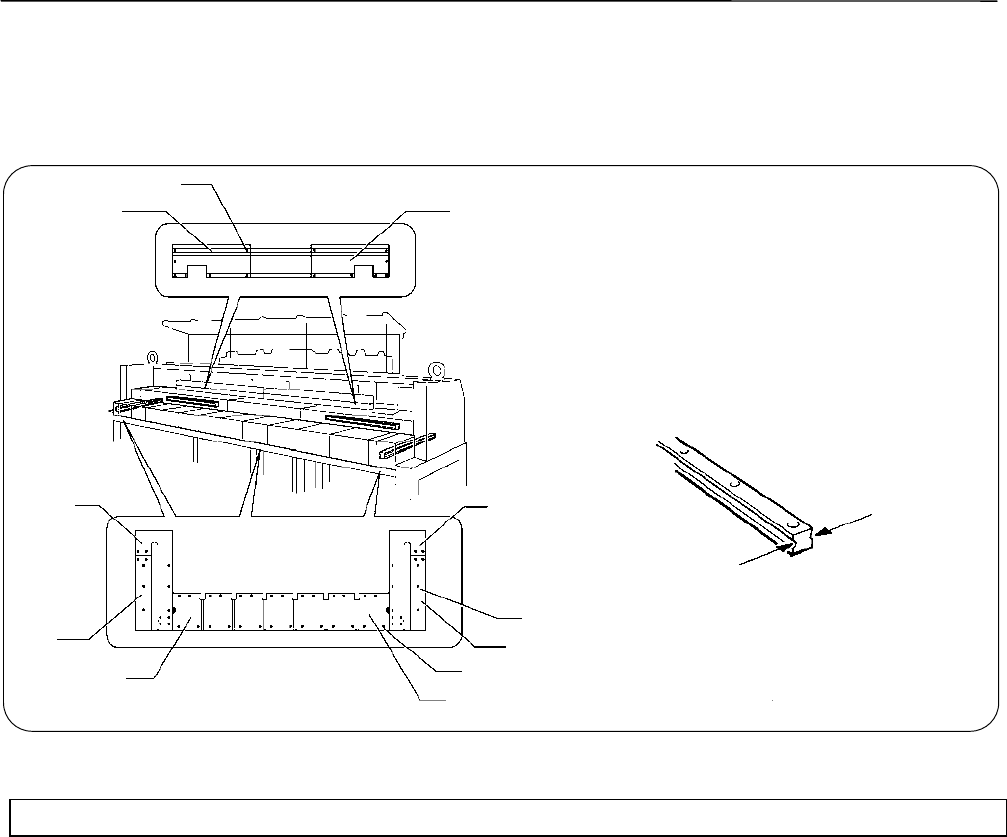
2-3 Preparation of Needle Bar Case........................................................................................................................2-6
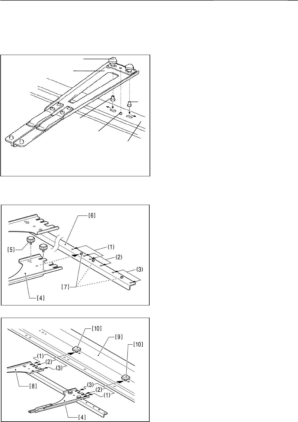
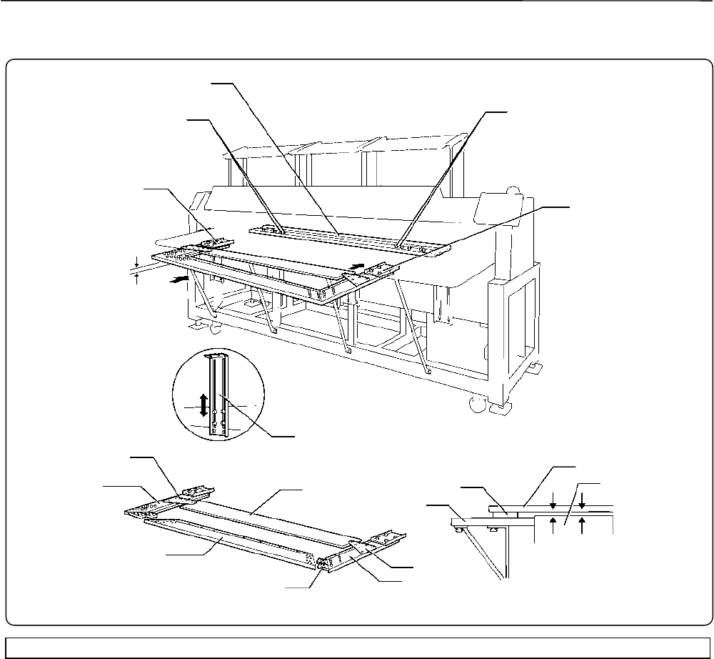
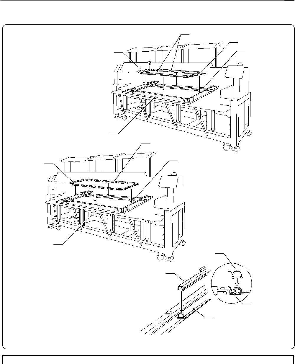
2-4 Mounting of Table...............................................................................................................................................2-7
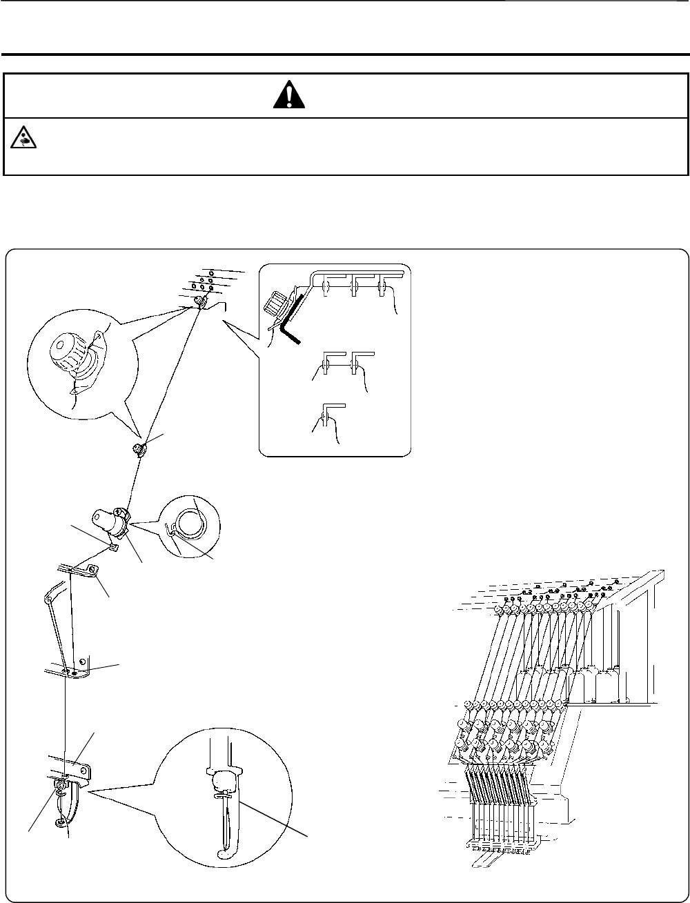
2-5 Mounting of Cotton Stand................................................................................................................................2-10
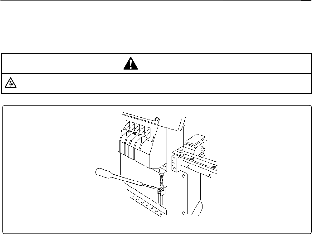
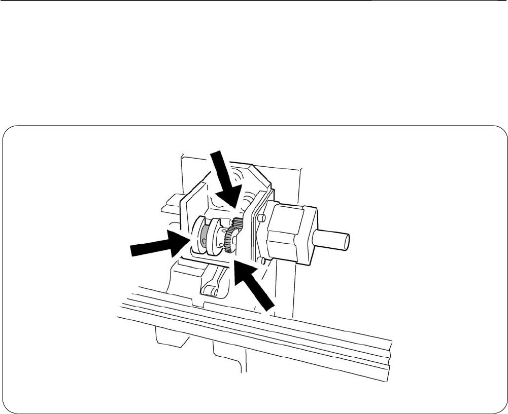
2-6 Lubrication to Needle Bar Case.......................................................................................................................2-11
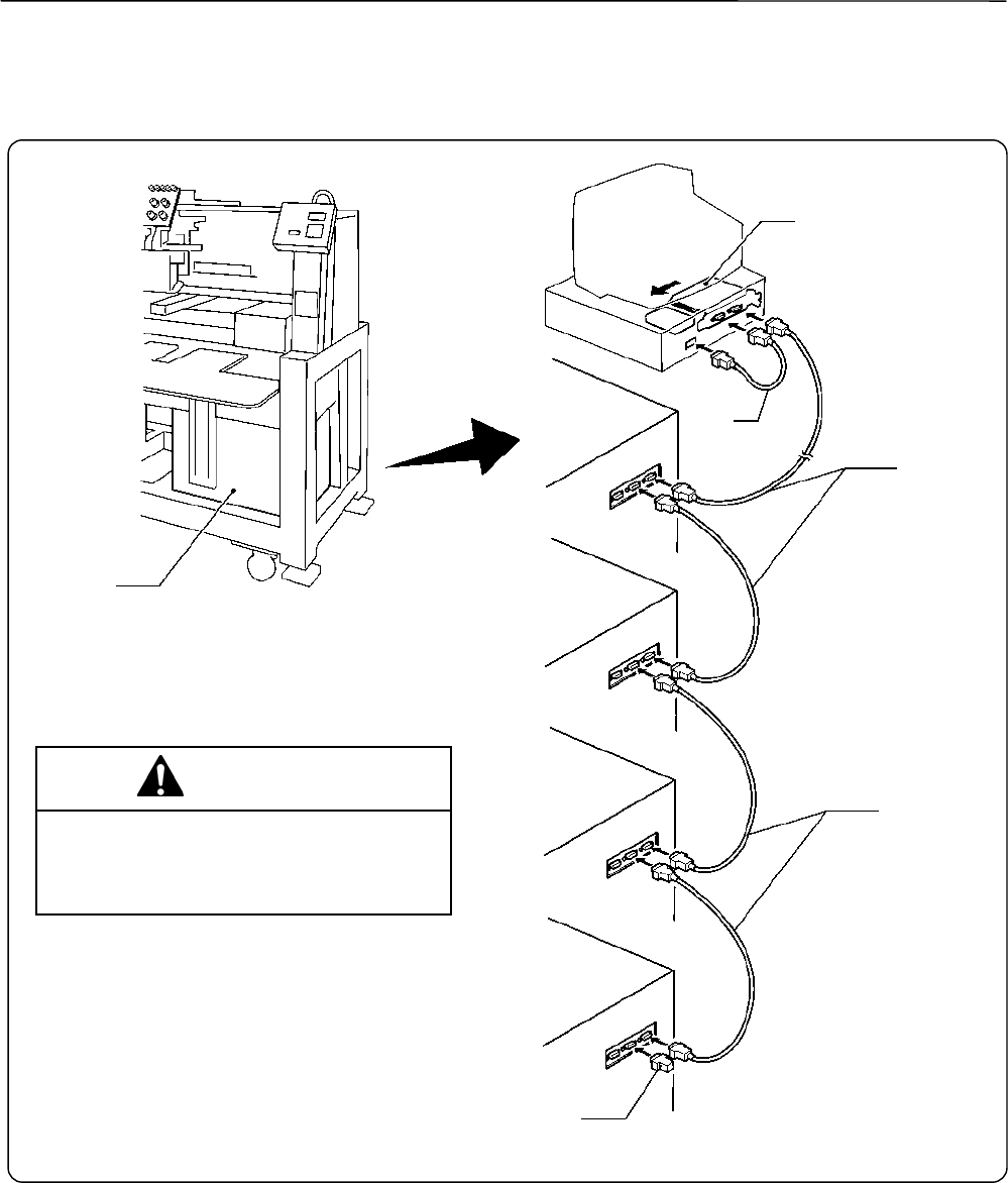
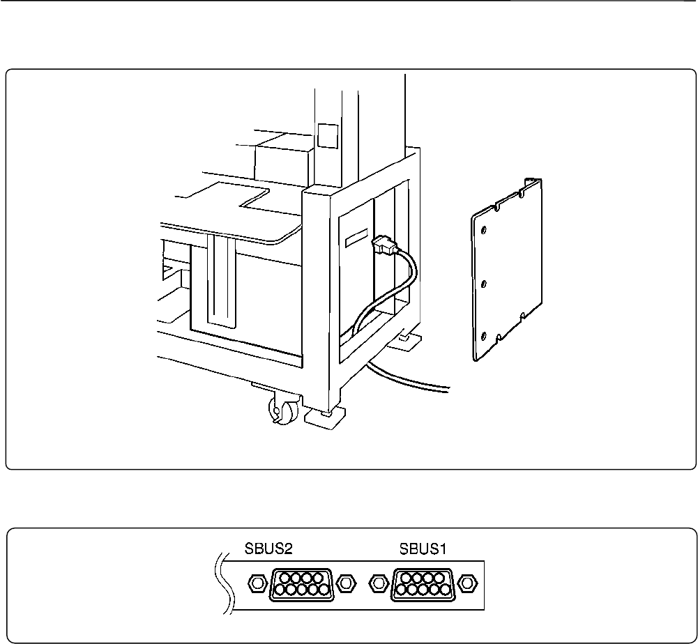
2-7 Connection of Personal Computer to Machines (for connecting 4 sets)..........................................................2-12
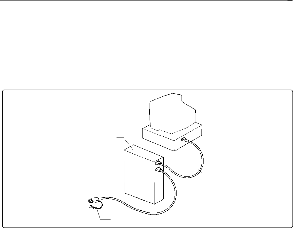
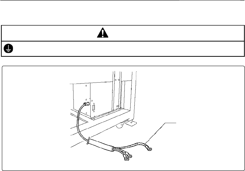
2-8 Connection of Power Supply............................................................................................................................2-14
2-10 Installation of Software...................................................................................................................................2-16
3. Preparation for Embroidering................................................................................................................................2-17
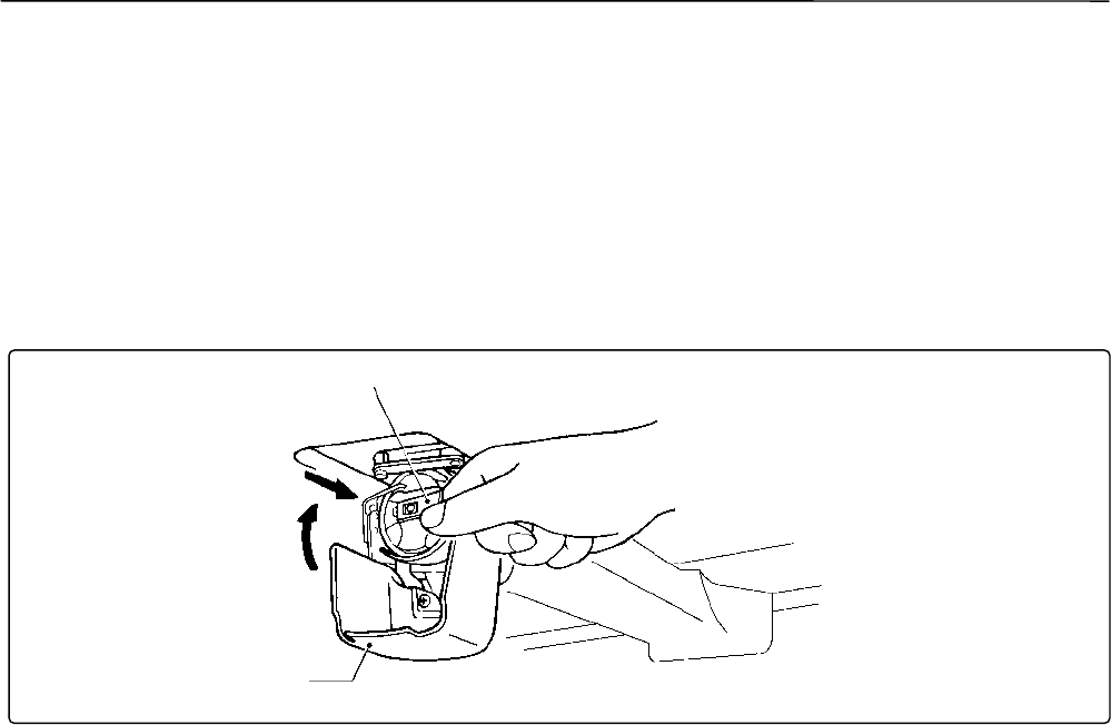
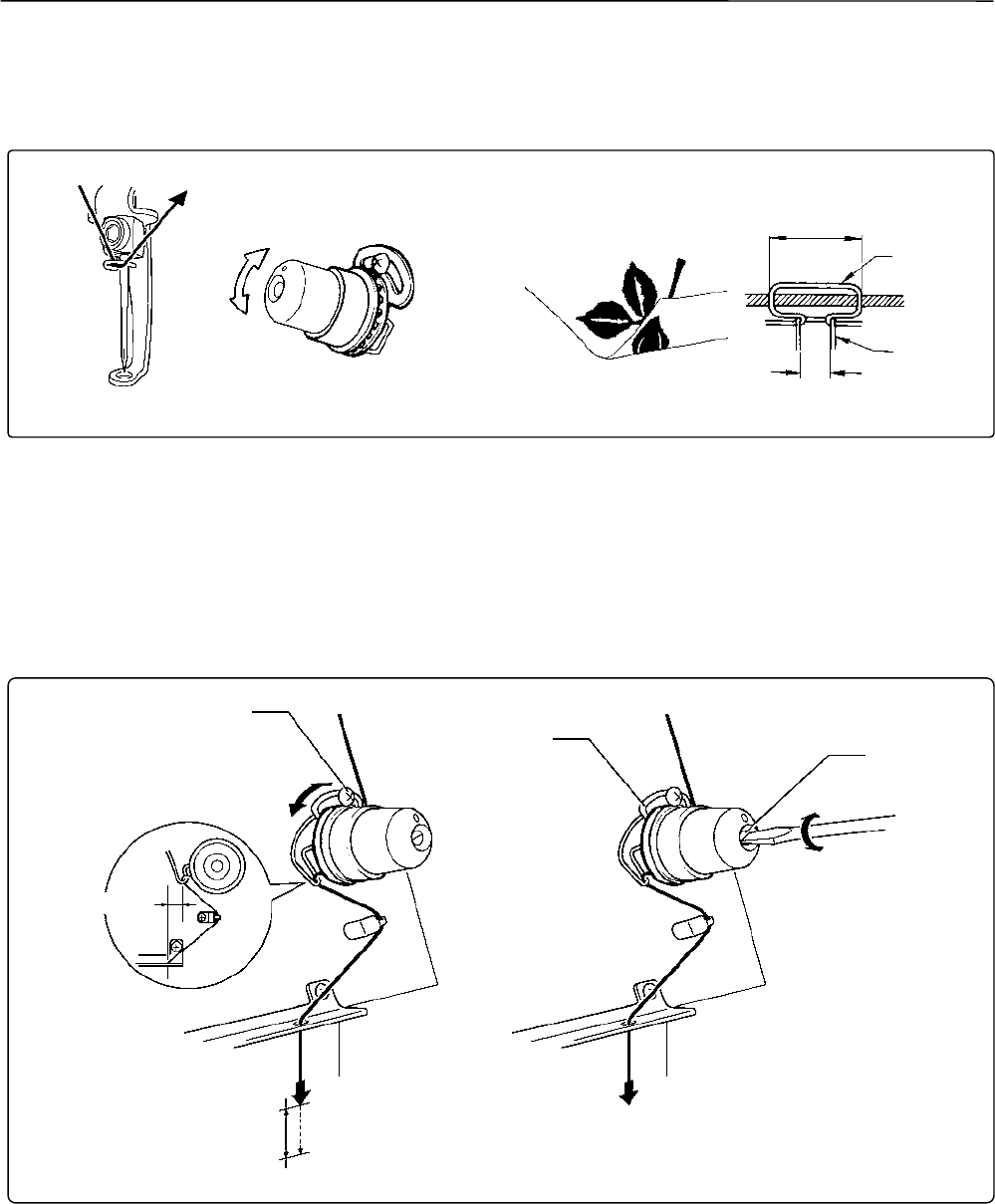
3-2 Replacement of Bobbin....................................................................................................................................2-19
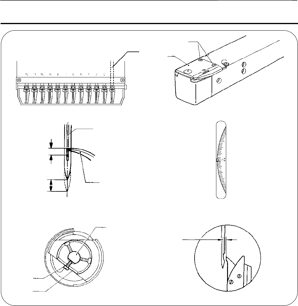
3-3 Replacing and Selecting Needle......................................................................................................................2-21
3-4 Attachment of Embroidery Hoop and Frame....................................................................................................2-22
3-5 Adjustment of Thread Tension..........................................................................................................................2-26
Chapter 3 Embroidering Procedures
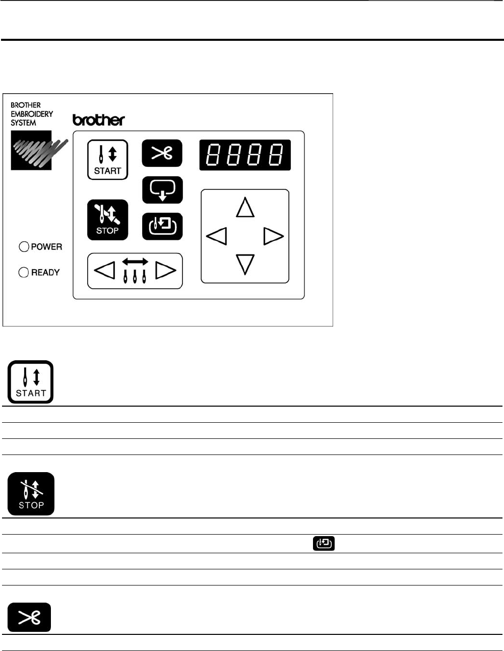
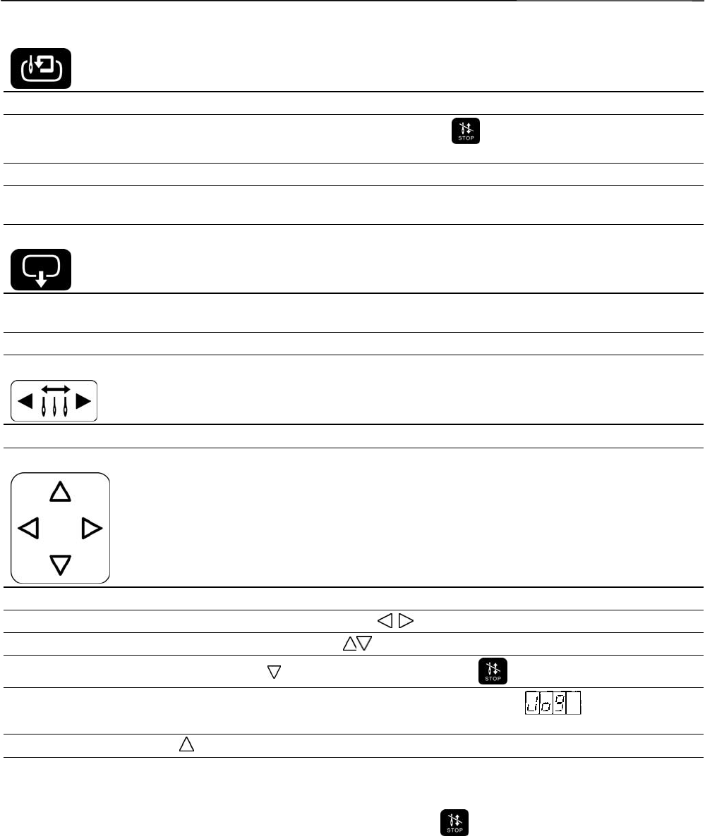
Functions of Operation Panel......................................................................................................................................3-2
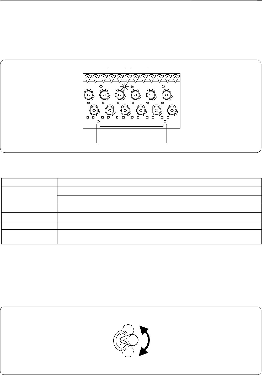
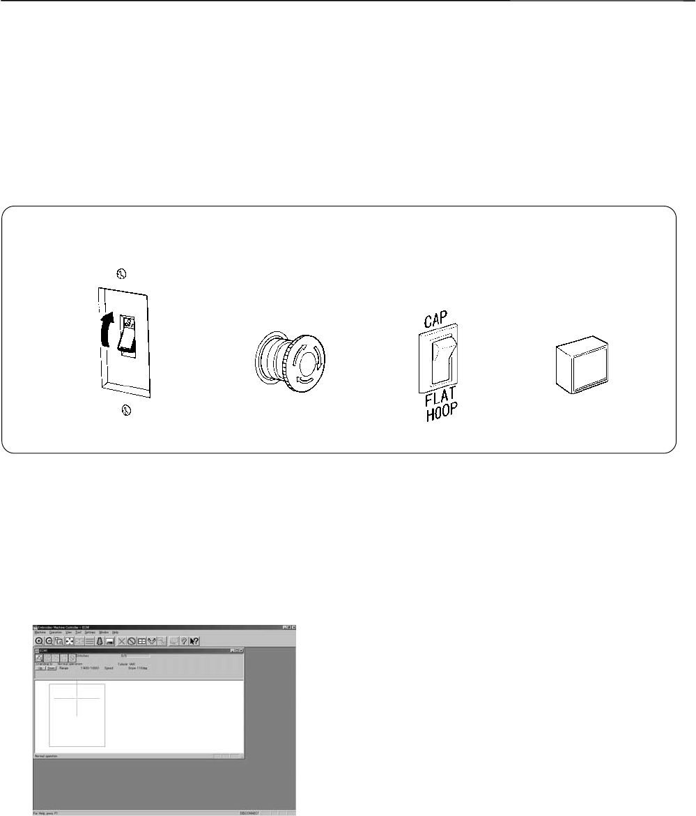
Switches at Machine Heads.....................................................................................................................................3-4
Lamps and switches on the thread tension stand....................................................................................................3-5
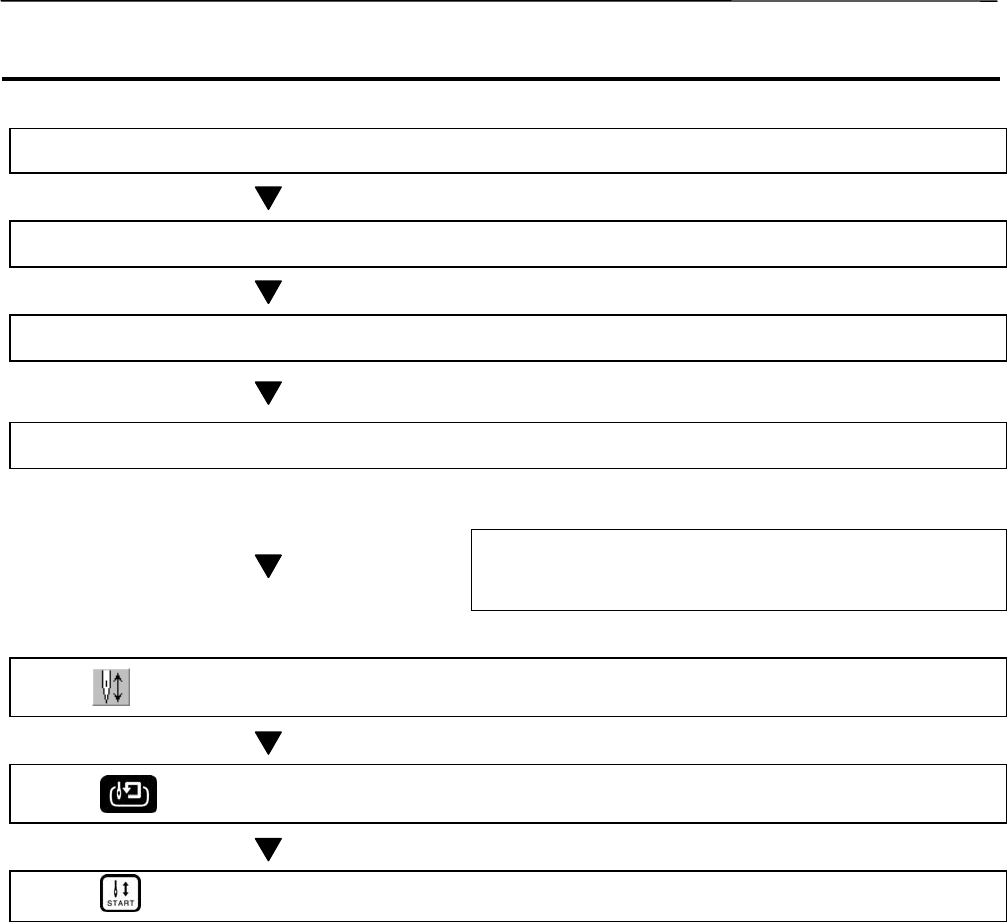
Flowchart of Preparation for Embroidering................................................................................................................3-6
Run the Software.....................................................................................................................................................3-7
Turn on the Machine Power.....................................................................................................................................3-7
Register the Machine Name.....................................................................................................................................3-8
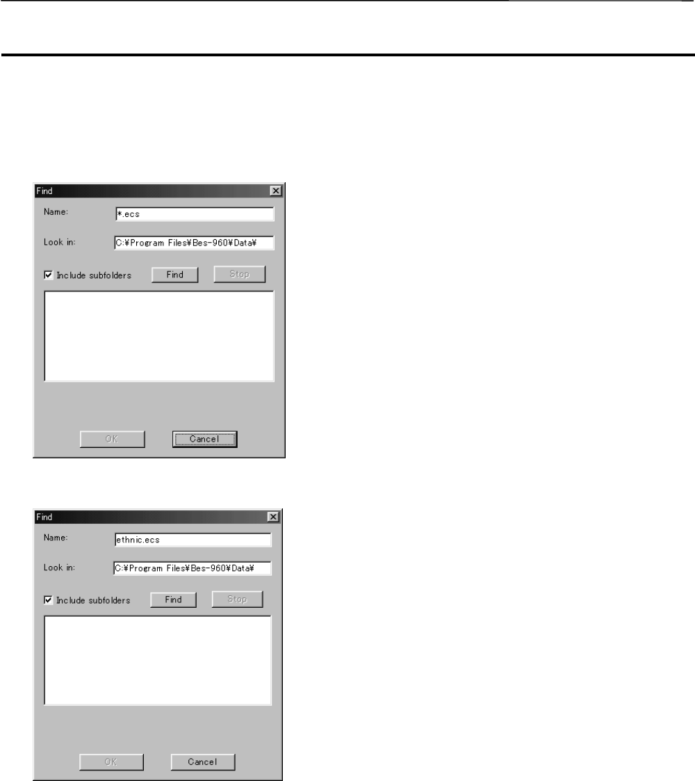
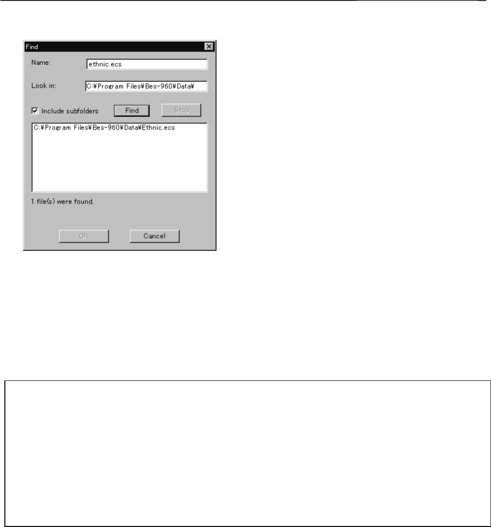
Retrieve the Embroidery Data..................................................................................................................................3-8
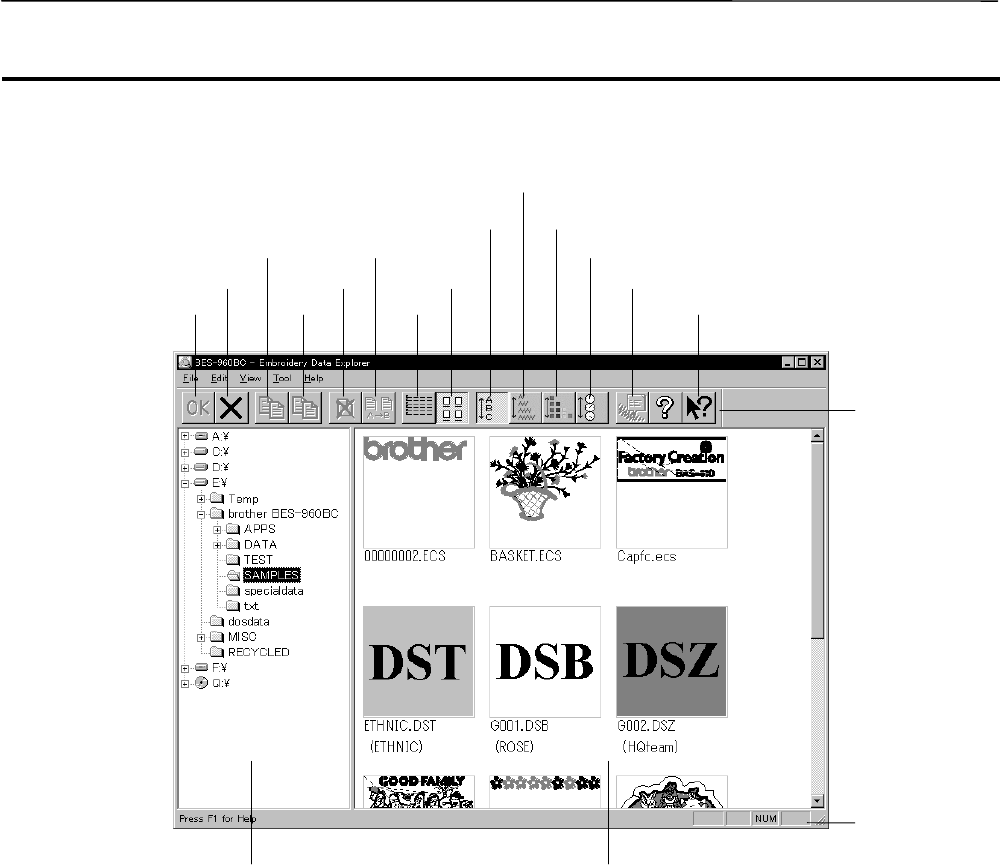
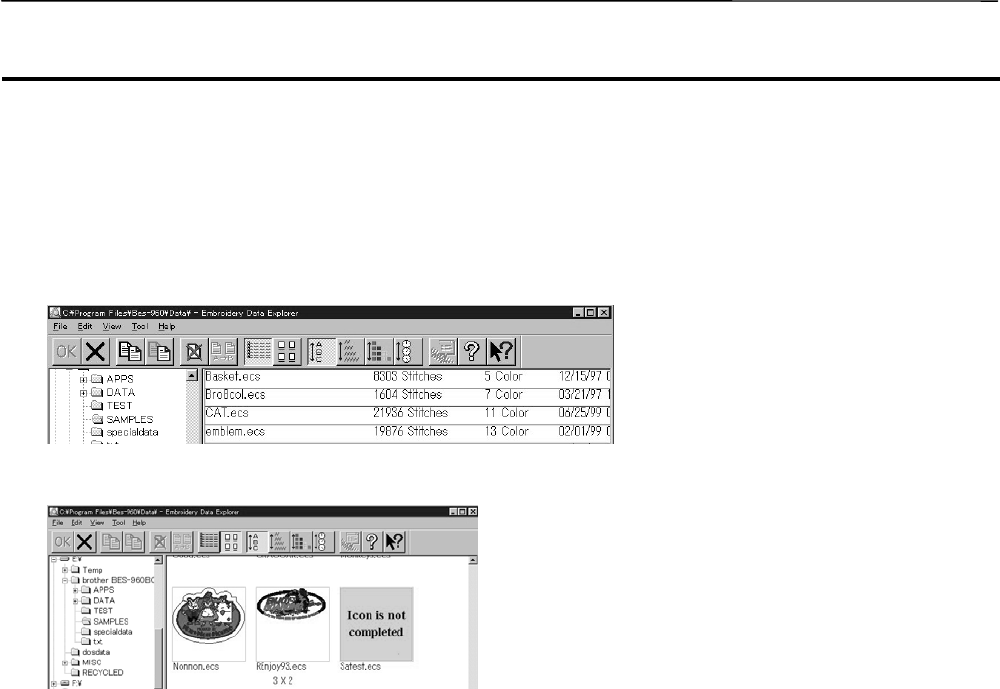
Description of Screen..................................................................................................................................................4-3
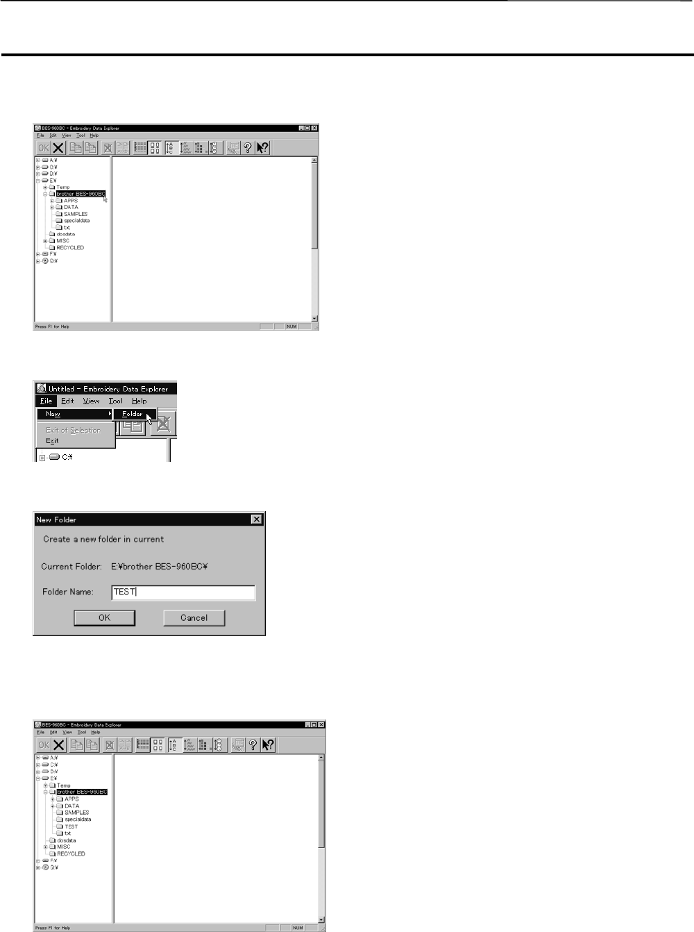
Creating a Directory.....................................................................................................................................................4-4
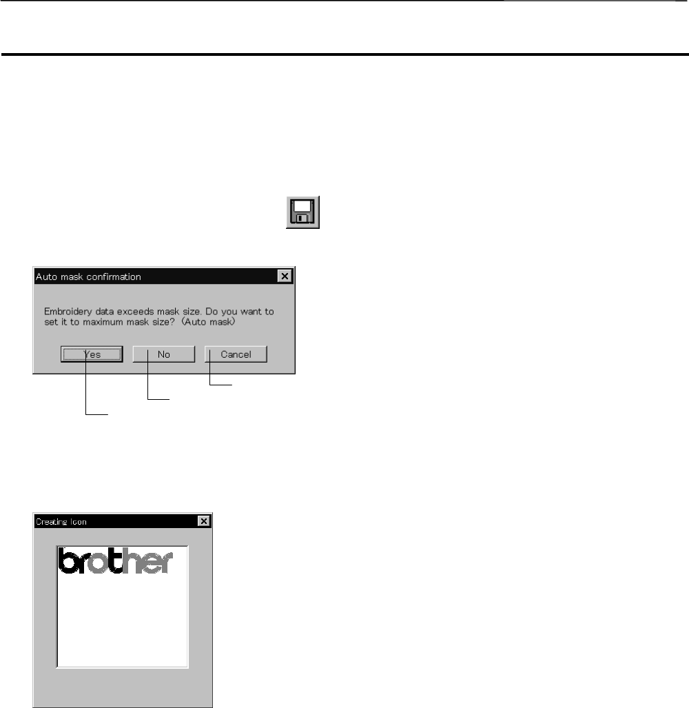
Select from Menu.....................................................................................................................................................4-7
Select from Menu.....................................................................................................................................................4-8
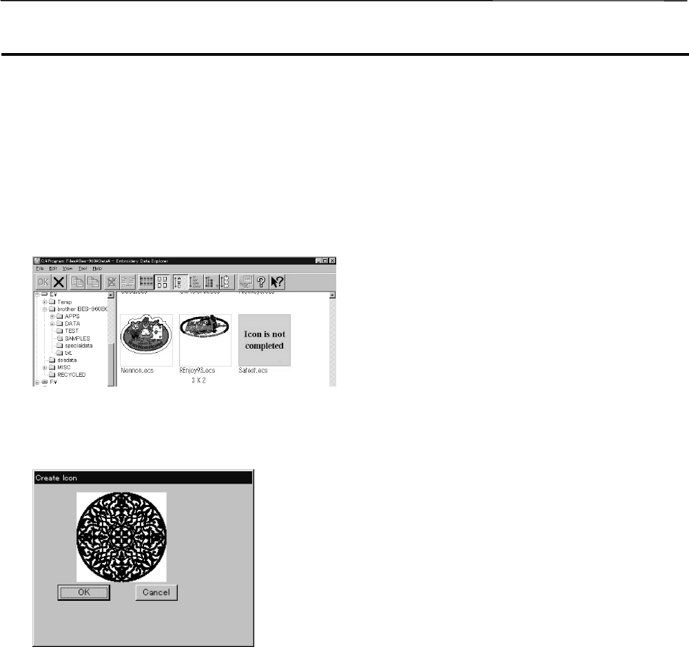
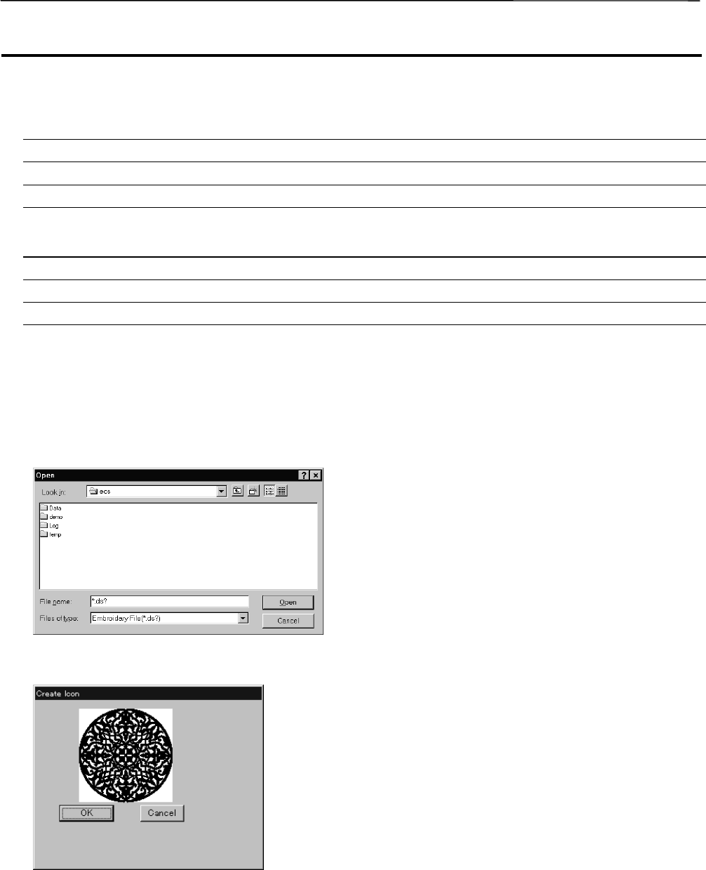
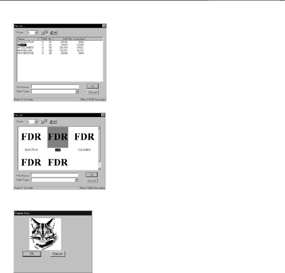
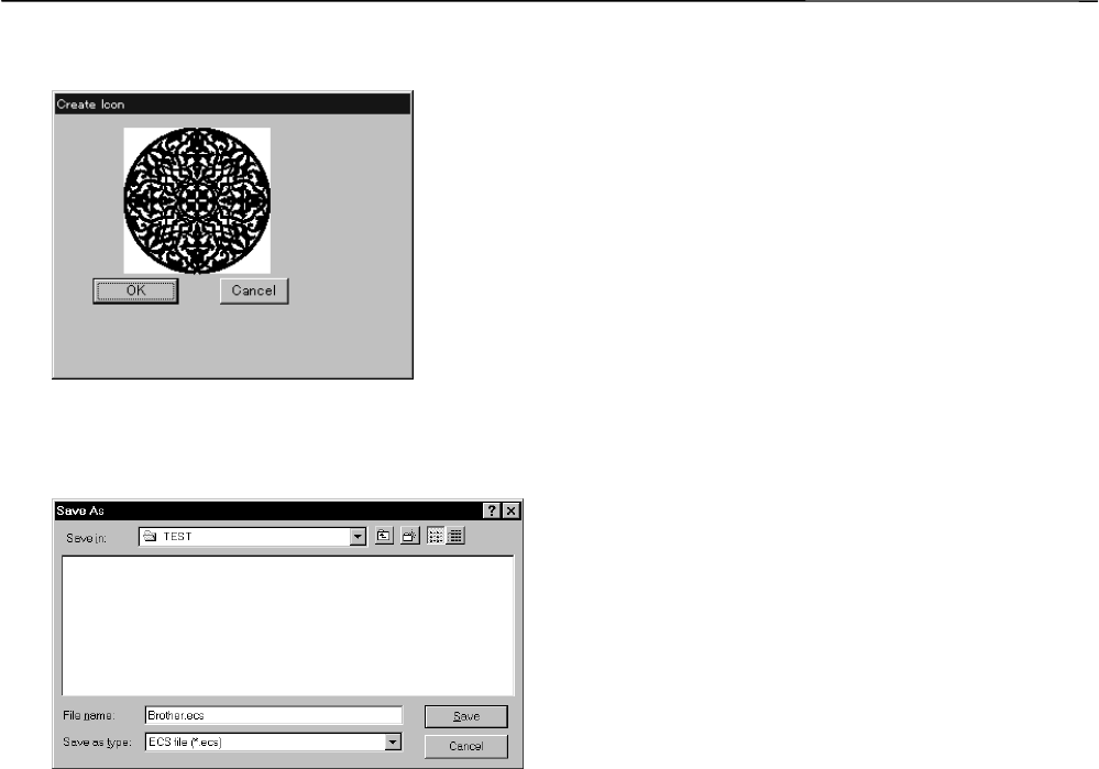
Recreate an icon.........................................................................................................................................................4-10
Select All .....................................................................................................................................................................4-11
Reading Data in Floppy Disk.....................................................................................................................................4-16
Reading DOS Format Data....................................................................................................................................4-16
Converting the Non DOS format data....................................................................................................................4-18
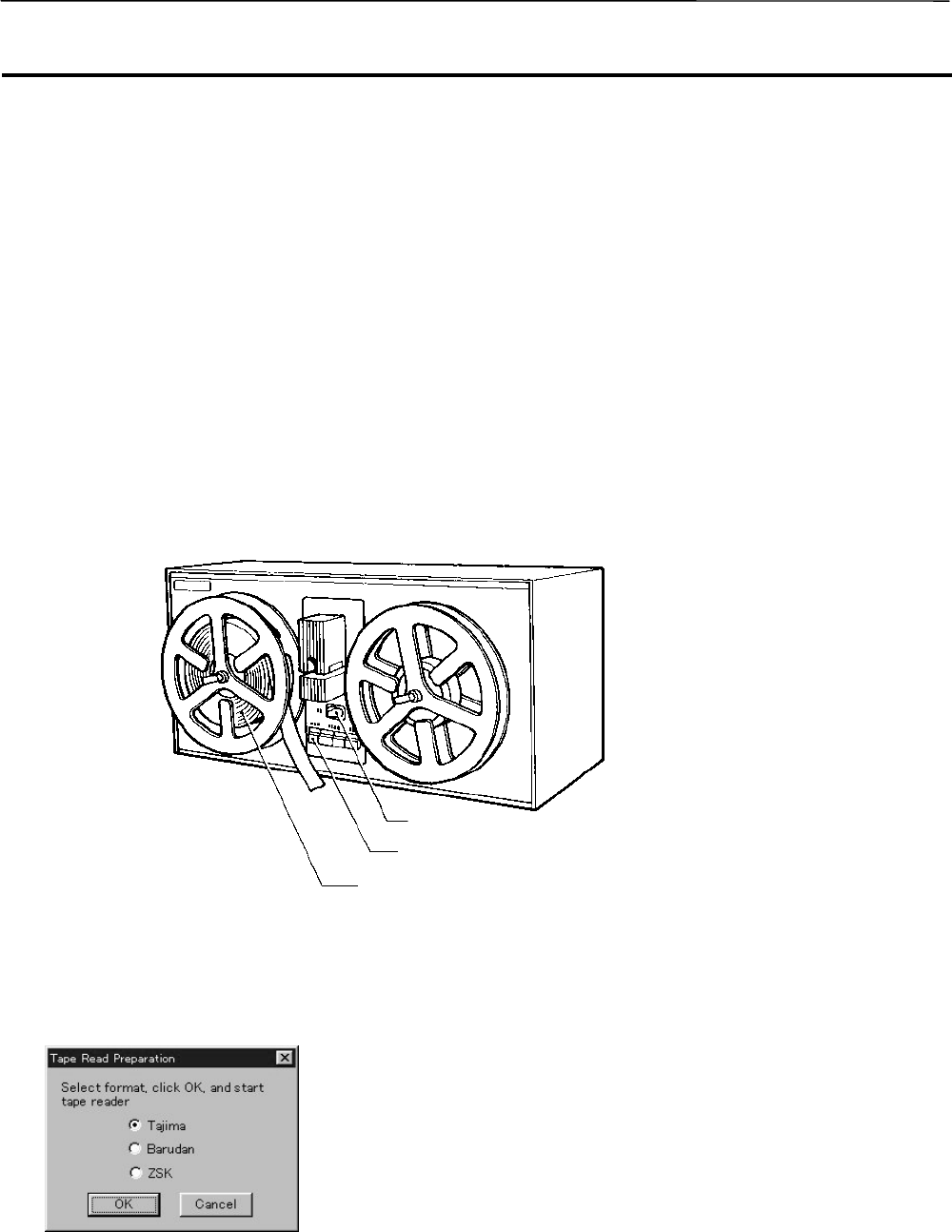
Reading Data in Paper Tape ......................................................................................................................................4-22
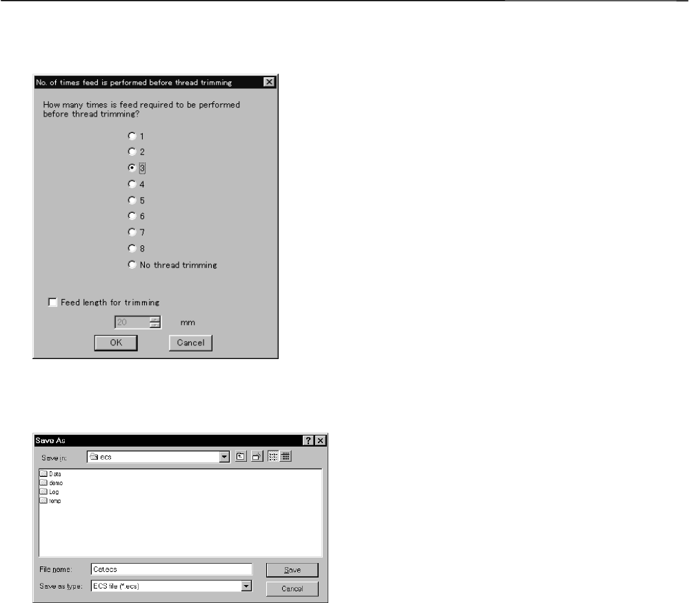
Settings for Data Reading..........................................................................................................................................4-24
Writing Data in DST Format.......................................................................................................................................4-25
Description of Screen..................................................................................................................................................5-4
Trim and pause........................................................................................................................................................5-8
Needle Bar and Speed Range.................................................................................................................................5-9
Status Bar..............................................................................................................................................................5-14
Back to Previous Status.............................................................................................................................................5-15
Point Symmetry.....................................................................................................................................................5-17
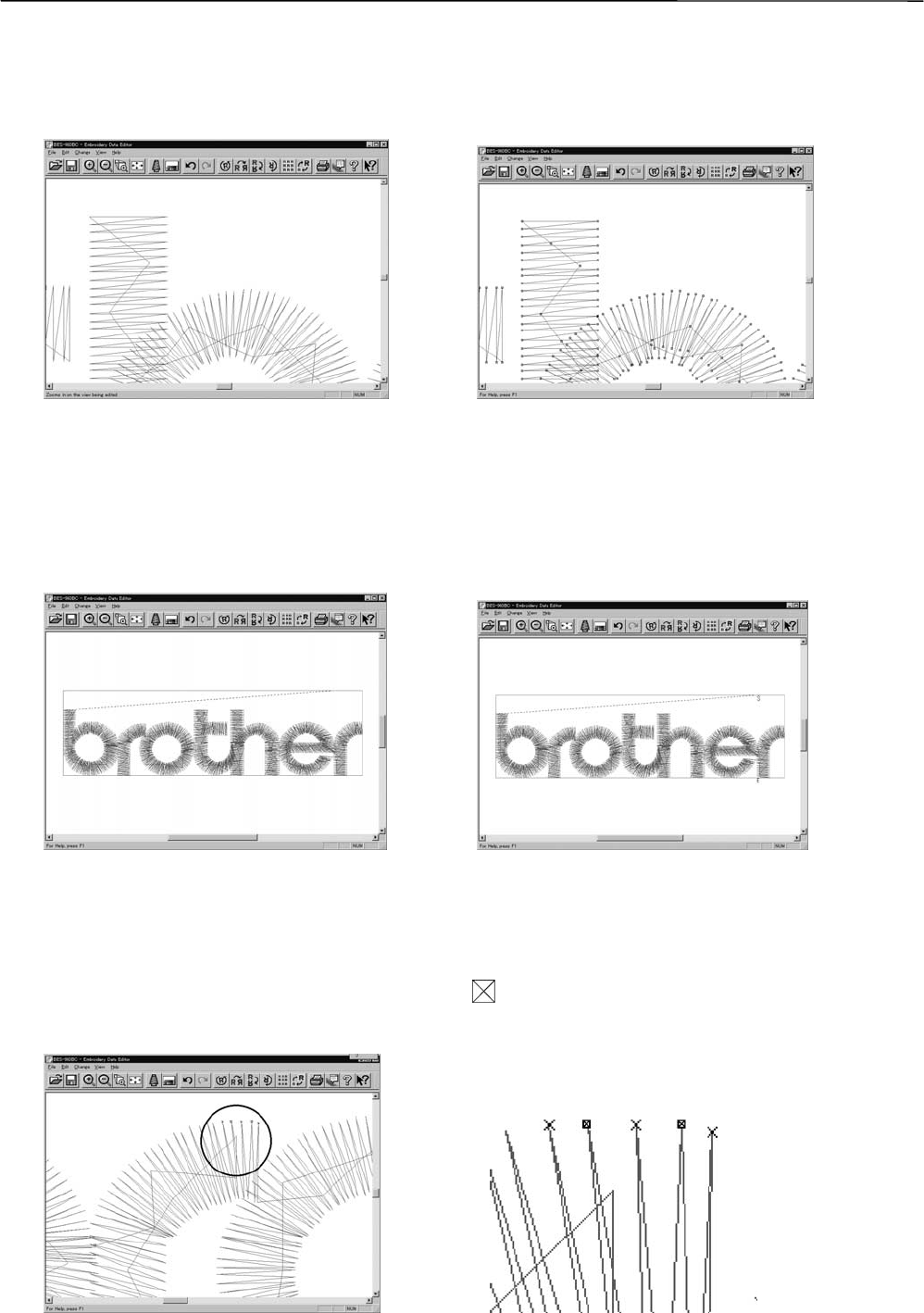
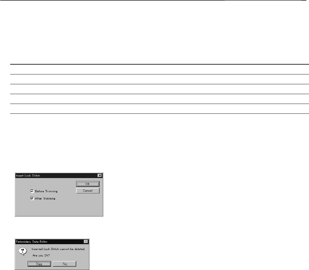
Insert or Delete Code.............................................................................................................................................5-21
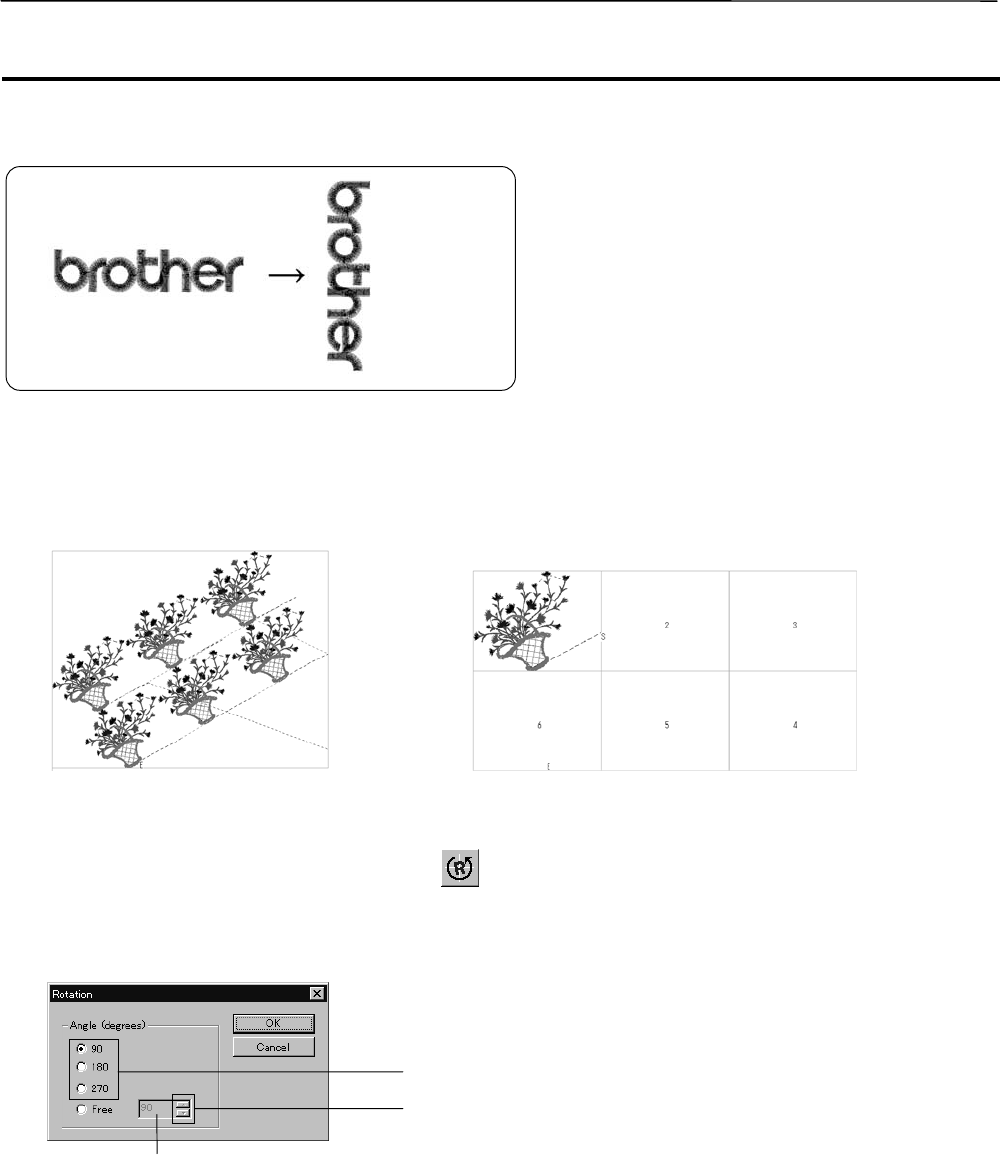
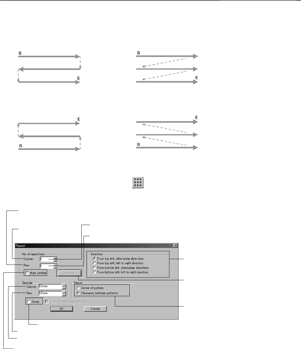
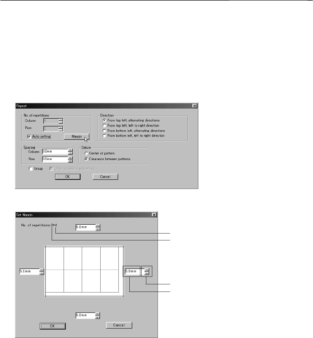
Setting Group for Repetition...................................................................................................................................5-27
Selecting from Menu..............................................................................................................................................5-27
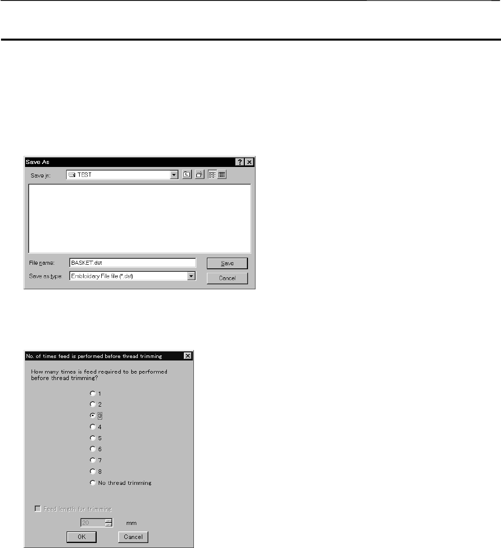
Save As..................................................................................................................................................................5-31
When the Power to the Machine is Off.....................................................................................................................6-2
When the Power to the Machine is On.....................................................................................................................6-2
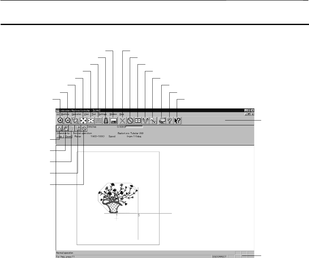
Description of Screen...................................................................................................................................................6-5
Settings before Turning On the Machine....................................................................................................................6-6
Displaying the Tool Bar............................................................................................................................................6-6
Displaying the Status Bar.........................................................................................................................................6-7
Upgrading the Version of Interface Board................................................................................................................6-7
Communication Port.................................................................................................................................................6-7
Settings after Turning Power On.................................................................................................................................6-9
Status Bar ................................................................................................................................................................6-9
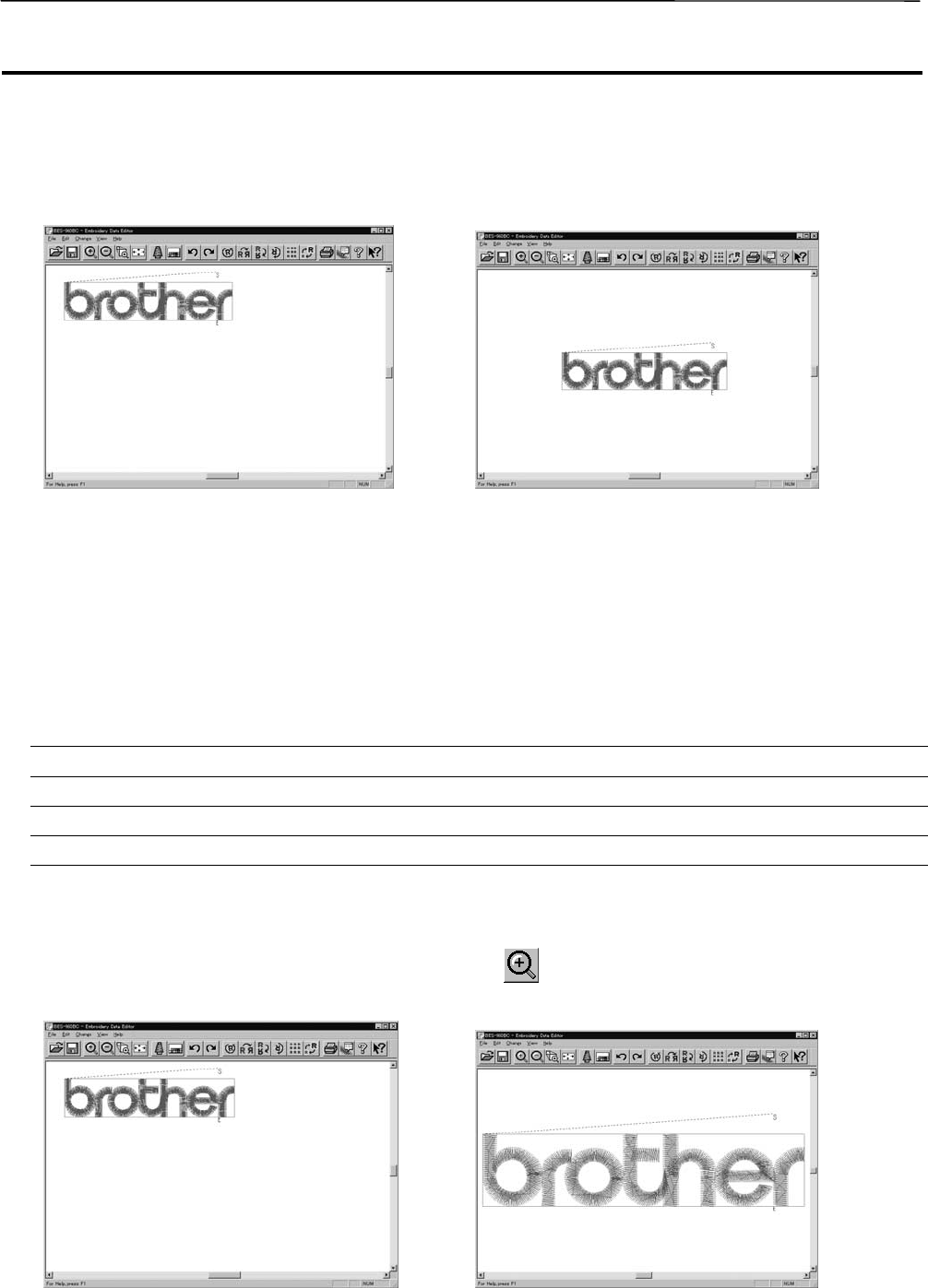
Zoom In Specified Range.......................................................................................................................................6-10
Fit to Window.........................................................................................................................................................6-10
Hoop position fine adjustment................................................................................................................................6-11
Needle Bar and Speed Range...............................................................................................................................6-13
Minimizing and Aligning Windows..........................................................................................................................6-21
Copying Data to Other Machines...........................................................................................................................6-23
Upgrading the Machine Program...........................................................................................................................6-24
14BE-1204B-BC • BE-1204C-BC • BE-1206B-BC
Contents
Setting the Machine....................................................................................................................................................6-25
Same Speed Range ..............................................................................................................................................6-26
Head Operation Suspend......................................................................................................................................6-27
Automatic Step Back .............................................................................................................................................6-33
End of embroidery.................................................................................................................................................6-34
Activate escape with pause...................................................................................................................................6-37
Short stitch speed reduction..................................................................................................................................6-38
Area Trace.............................................................................................................................................................6-40
Trace with needle No.1..........................................................................................................................................6-40
Show Setting.........................................................................................................................................................6-42
Save Setting..........................................................................................................................................................6-45
Moving the Home Position ........................................................................................................................................6-52
Entering in the Step-forward/Step-back Mode.......................................................................................................6-53
Setting Step-forward/Back Distance or Timing.......................................................................................................6-54
Save As... ..............................................................................................................................................................6-59
Running Other Programs...........................................................................................................................................6-61
1-1 Power Source....................................................................................................................................................7-2
1-2 Preparation for Embroidering.............................................................................................................................7-2
2-1 Stopping the Machine........................................................................................................................................7-3
2-2 Emergency Stop of the Machine........................................................................................................................7-3
3. Permission for Hoop Movement..............................................................................................................................7-4
4. Measures against Thread Breakage........................................................................................................................7-5
5. Jog Embroidering.....................................................................................................................................................7-8
7. Area Check ..............................................................................................................................................................7-10
7-2 Automatic Hoop Movement in Area..................................................................................................................7-10
8. Jog Switches...........................................................................................................................................................7-11
8-1 Hoop Movement to Start Position.....................................................................................................................7-11
8-2 Inching Mode during Embroidering (Forcible Hoop Movement).......................................................................7-12
Description of Screen...................................................................................................................................................8-3
Display Example of Details ......................................................................................................................................8-5
Display Example of Thread Breakage Information on Needle Bar...........................................................................8-6
Display Example of Thread breakage Information in Pattern...................................................................................8-7
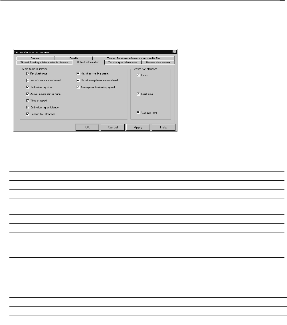
Display Example of Output Information....................................................................................................................8-8
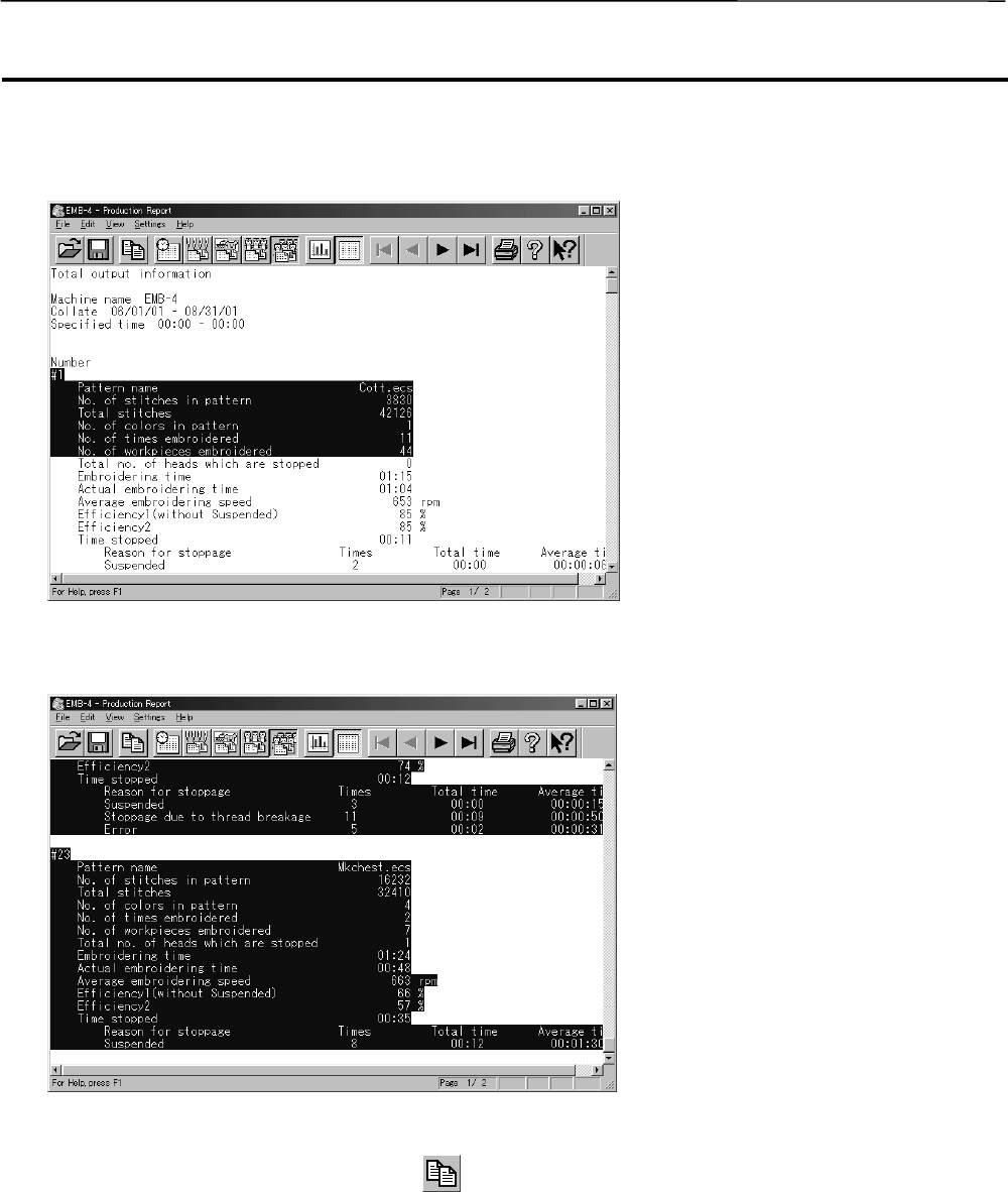
Display Example of Total Output Information.........................................................................................................8-10
Thread Breakage Information on Needle Bar.........................................................................................................8-14
Thread Breakage Information in Pattern................................................................................................................8-14
Total Output Information.........................................................................................................................................8-16
Recess Time Setting..............................................................................................................................................8-17
Save As CSV................................................................................................................................................................8-18
Printing Production Report........................................................................................................................................8-19
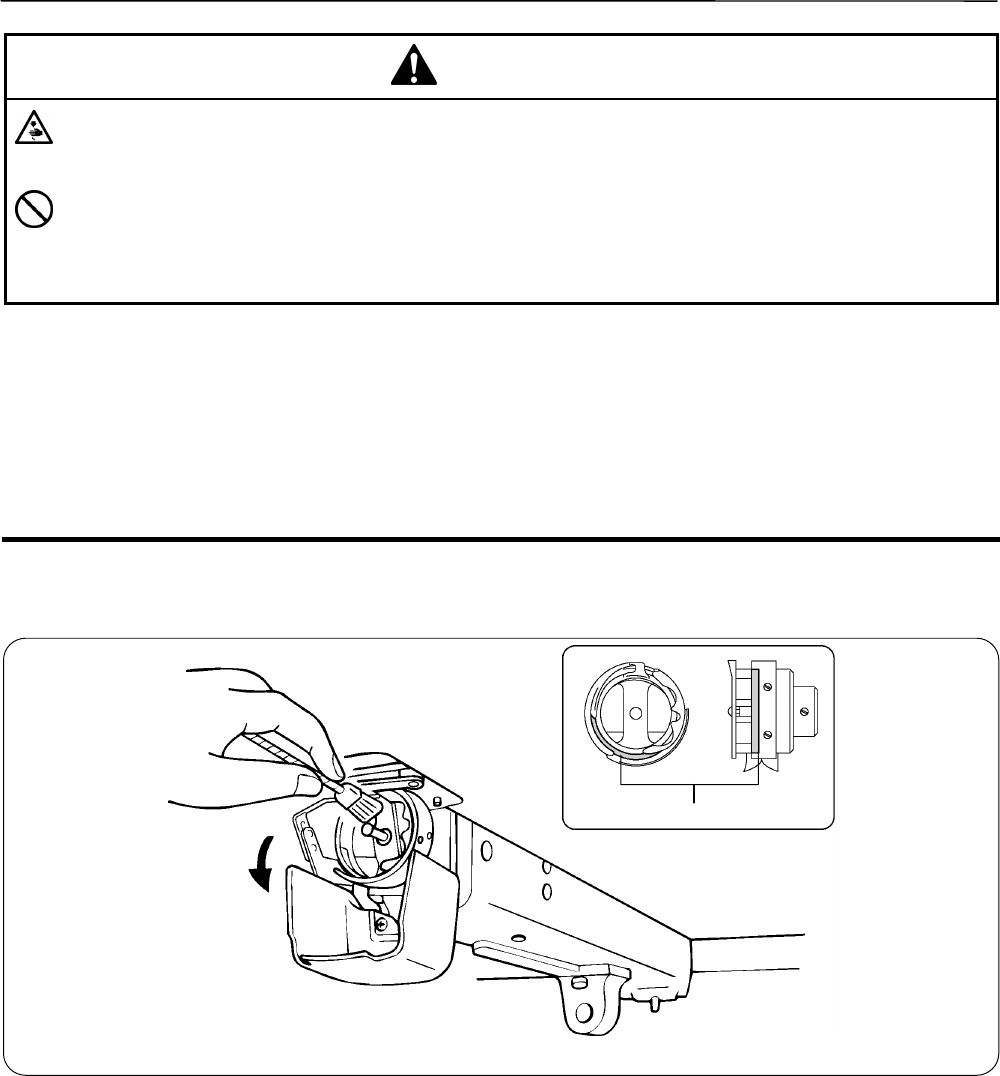
1-1 Cleaning and Lubrication of Rotary Hook..........................................................................................................9-2
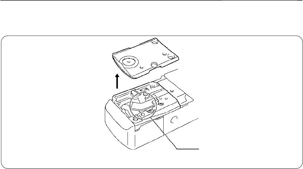
1-2 Cleaning of Needle Plate...................................................................................................................................9-3
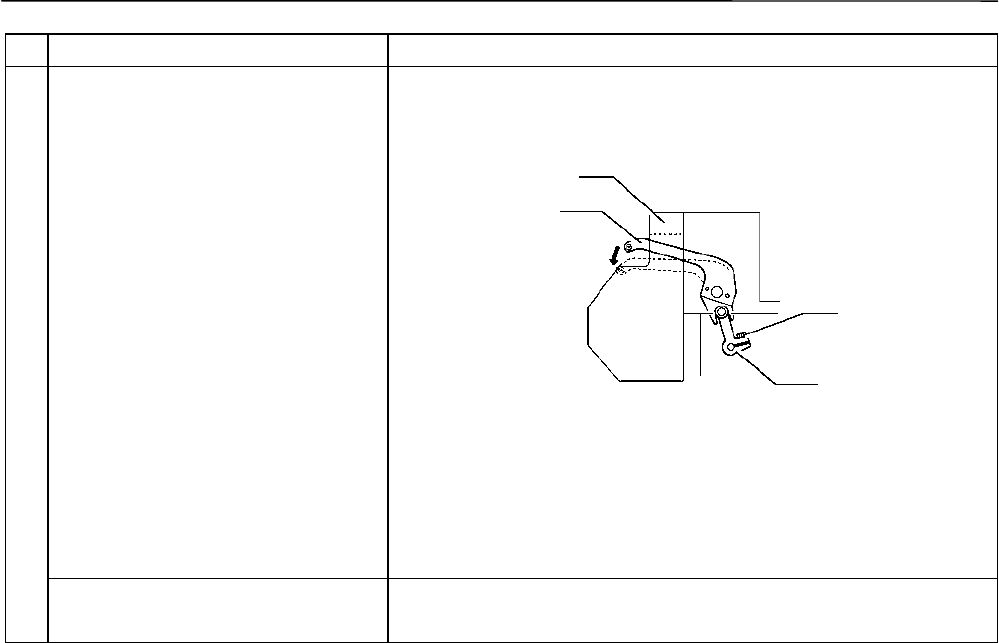
3-4 Needle bar flip-up mechanism...........................................................................................................................9-9
1. Adjusting Needle Bar Height.................................................................................................................................10-2
2. Attachment and Adjustment of Rotary Hook........................................................................................................10-6
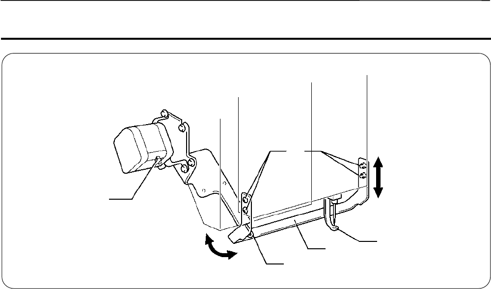
3. Adjustment of Presser Foot Height.......................................................................................................................10-8
Personal Computer Section ......................................................................................................................................12-8
Chapter 13 Connection and Installation of Optional Equipment
Gebruikershandleiding.com neemt misbruik van zijn services uitermate serieus. U kunt hieronder aangeven waarom deze vraag ongepast is. Wij controleren de vraag en zonodig wordt deze verwijderd.
Product:
Spelregels forum
Om tot zinvolle vragen te komen hanteren wij de volgende spelregels:
lees eerst de handleiding door;
controleer of uw vraag al eerder door iemand anders is gesteld;
probeer uw vraag zo duidelijk mogelijk te stellen;
heeft u een probleem en al geprobeerd om dit op te lossen, vermeld dit erbij aub;
heeft u een oplossing gekregen van een bezoeker dan horen wij dat graag in dit forum;
wilt u een reactie geven op een vraag of antwoord, gebruik dan niet dit formulier maar klik op de knop 'reageer op deze vraag';
uw vraag wordt direct op de website gezet; vermijd daarom persoonlijke gegevens in te vullen;
Belangrijk! Als er een antwoord wordt gegeven op uw vraag, dan is het voor de gever van het antwoord nuttig om te weten als u er wel (of niet) mee geholpen bent! Wij vragen u dus ook te reageren op een antwoord.
Belangrijk! Antwoorden worden ook per e-mail naar abonnees gestuurd. Laat uw emailadres achter op deze site, zodat u op de hoogte blijft. U krijgt dan ook andere vragen en antwoorden te zien.
Abonneren
Abonneer u voor het ontvangen van emails voor uw Brother BE-1204C-BC PC control bij:
nieuwe vragen en antwoorden
nieuwe handleidingen
U ontvangt een email met instructies om u voor één of beide opties in te schrijven.
Ontvang uw handleiding per email
Vul uw emailadres in en ontvang de handleiding van Brother BE-1204C-BC PC control in de taal/talen: Engels als bijlage per email.
De handleiding is 7,66 mb groot.
U ontvangt de handleiding per email binnen enkele minuten. Als u geen email heeft ontvangen, dan heeft u waarschijnlijk een verkeerd emailadres ingevuld of is uw mailbox te vol. Daarnaast kan het zijn dat uw internetprovider een maximum heeft aan de grootte per email. Omdat hier een handleiding wordt meegestuurd, kan het voorkomen dat de email groter is dan toegestaan bij uw provider.
Stel vragen via chat aan uw handleiding
Stel uw vraag over deze PDF
Uw handleiding is per email verstuurd. Controleer uw email
Als u niet binnen een kwartier uw email met handleiding ontvangen heeft, kan het zijn dat u een verkeerd emailadres heeft ingevuld of dat uw emailprovider een maximum grootte per email heeft ingesteld die kleiner is dan de grootte van de handleiding.
Er is een email naar u verstuurd om uw inschrijving definitief te maken.
Controleer uw email en volg de aanwijzingen op om uw inschrijving definitief te maken
U heeft geen emailadres opgegeven
Als u de handleiding per email wilt ontvangen, vul dan een geldig emailadres in.
Uw vraag is op deze pagina toegevoegd
Wilt u een email ontvangen bij een antwoord en/of nieuwe vragen? Vul dan hier uw emailadres in.