533128
16
Verklein
Vergroot
Pagina terug
1/20
Pagina verder
bitte aufbewahren
veuillez conserver
si prega di conservarle
please keep
por favor, guardar
por favor, guardar
lütfen saklayýnýz
Assembly instructions
Einbauanleitung
Notice de montage
Istruzioni di Montaggio
Instrucciones de montaje
Instruçoes de montagem
пожалуйста, сохраните данное руководство
Montaj talimatlarý
Руководство по монтажу
~44
~62
1
s.v.p. bewaren
Installatievoorschrift
~
.
-
.
43
53
en
de
fr
it
es
pt
nl
tr
ru
2
3
4
4a
4b
70
5
6
7
7a
7c
7d
8
8a
7b
9
10
10 a
11
en
Read the appliance's instructions
before installing and using.
The graphics in these Assembly
instructions are given as a guide only.
The manufacturer is exempt from all
liability if this manual's requirements
are not complied with.
Safety instructions
All operations relating to installation,
regulation and conversion to other
types of gas must be carried out by
an authorised installation engineer,
respecting applicable regulations,
standards and the specifications of
the gas and electricity providers.
Before you begin, turn off the
appliance's electricity and gas
supply.
You are recommended to contact the
Technical Assistance Service to
convert to another type of gas.
This appliance has been designed for
home use only, not for commercial or
professional use. This appliance
cannot be installed on yachts or in
caravans. The warranty will only be
valid if the appliance is used for the
purpose for which it was designed.
Before installing, you need to check
that local distribution conditions (gas
type and pressure) and the appliance's
adjustment are compatible (see table
I ). The appliance's adjustment
conditions are written on the label or
the specifications plate.
This appliance can only be installed in
a well-ventilated place in accordance
with existing regulations and ventilation
specifications. The appliance must not
be connected to a combustion product
evacuation device.
The supply cable must be attached to
the unit to prevent it from touching hot
parts of the oven or hob.
Appliances with electrical supply must
be earthed.
Do not tamper with the appliance's
interior. If necessary, call our Technical
Assistance Service.
Before installing
This appliance is class 3 type,
according to the EN 30-1-1 regulation
for gas appliances: built-in appliance.
These individual appliances can be
combined with other identical
appliances and/or with conventional
hobs of the same make, using the joint
accessory.
See the catalogue for details.
The units next to the appliance must be
made of non-flammable materials. The
laminated covering and glue for
adhering it must be heat resistant.
This appliance cannot be installed
above fridges, washing machines,
dishwashers or similar.
An oven must have a power cooling
fan to install a hob above it.
Check the oven's dimensions in its
installation manual.
If an extractor fan is installed, you must
follow the installation manual's
instructions, always keeping a
minimum distance of 650 mm to the
hob.
Preparation of kitchen unit
(fig. 1-2)
Make an appropriate size cut in the
work surface.
If the hob is electric or mixed (gas and
electricity) and there is no oven below,
place a non-flammable separator (e.g.
metal or plywood) 10 mm from the
bottom of the hob. This will prevent
access to the base of the hob.
If the hob is gas, it is recommendable
to place the separator at the same
distance.
On wood work surfaces, varnish the
cutting surfaces with a special glue.
This protects them from moisture
which could collect under the work
surface.
Installation of appliance
The clips and the adhesive seal
(underside of the hob) are factory-
fitted: do not under any circumstances
remove them. The seal ensures that
the entire work surface will be
watertight, and prevents water
seepage.
In order to fit the appliance into the
kitchen unit, first place the hob in the
correct position then loosen each of
the clips so that they all turn freely (it is
not necessary to completely undo
them).
Insert and centre the hob.
Press the sides of the hob until it is
supported around its entire perimeter.
Turn the clips and tighten them fully.
Fig. 3
Removal of hob
Turn off the appliance's electricity and
gas supply.
Unscrew the clips and proceed in the
reverse order to installation.
Gas connection (fig. 4)
The end of the inlet connection point of
the gas hob has a 1/2” (20.955 mm)
thread that allows for:
- fixed connection.
- connection using a flexible metal pipe
(L min. 1 m - max. 3 m). In this case, it
is necessary to insert the accessory
(427950) and the watertight seal
(034308) supplied between the
manifold outlet and the gas supply.
Fig. 4a.
In this case, you must prevent the pipe
from coming into contact with moving
parts of the kitchen unit being inserted
(for example, a drawer) and prevent
access to any spaces which might
become obstructed.
If you need to connect the gas supply
horizontally, our Technical Assistance
Service can supply you with an L-tube
(code 173018) and a seal (code
034308). Fig. 4b.
Warning! If any connection is handled,
check the seal.
Danger of leaks.
The manufacturer is not liable for any
connection leaking, after being
handled.
Electric connection (fig. 5)
Check that the voltage and power of
the appliance are compatible with the
electrical installation.
The hobs are supplied with a power
cable with or without a wall socket
plug.
Provide an omnipolar cut-off switch
with a minimum contact separation of 3
mm (except for plug connections, if the
user has access to it).
Appliances with plugs must only be
connected to sockets that have earth
wires correctly installed.
This appliance is type “Y”: the supply
cable can only be changed by the
Technical Assistance Service and not
the user. The cable type and minimum
cross-section must be respected.
Changing the gas type
If the country's regulations allow, this
appliance can be adapted to other
types of gas (see specifications plate).
The components required for this are
in the transformation kit supplied
(depending on the model) available
from our Technical Assistance Service.
The following steps should be taken:
A) Changing the nozzles of the rapid,
semi-rapid and auxiliary burners on
the hob (fig. 6):
- Remove the pan supports, burner
covers and diffusers.
- Change the nozzles using the
spanner provided by our Technical
Assistance Service (code 424699),
taking special care to ensure that the
nozzle does not fall when it is removed
from the burner or when fitted.
Ensure that it is completely tightened in
order to guarantee the seal. Primary air
adjustment is not necessary with these
burners.
B) Changing the nozzles for double-
flame burners (fig. 7):
The glass panel and frame are fixed to
the rest of the hob using a clip
mounting system. The following steps
must be taken to remove the glass
panel and frame:
- Remove all the burner covers and pan
supports. Fig. 7a.
- Release the front clip fixing the
appliance to the kitchen unit by
removing the screw. Fig. 7b.
- Loosen the screws on the burners,
fig. 7c-7d, and remove the control
knobs from their respective housings.
Use the disassembly lever 483196
available from our Technical
Assistance Service. To release the
front clips, apply the lever in the area
shown in figures 8 according to the
hob model.
Never use the lever on glass edges
which have no trim or frame!
- To release the rear clips, carefully
raise the entire glass panel and frame,
as in fig. 8a.
Changing the outer flame nozzle
(fig. 9a):
- Loosen the clamp screw to release
the bushing by moving it backwards to
access the main nozzle easily. Fig. a1.
- Remove the outer flame nozzle by
turning it towards the left. Fig. a2-a3.
- Screw in the new outer flame nozzle.
Fig. a3-a4, as in table II.
- Adjust the distance of the airflow
adjusting bushing L2 according to the
value -Z- shown in table II. Fig. a5.
- Tighten the clamp screw. Fig. a6.
Changing the inner flame nozzle
(fig. 9b):
- Unscrew the part M3 from the
threaded part M2; to do this, hold the
threaded part in the opposite direction.
- Remove the pipe from the part M2.
Fig. b2.
- Disassemble the assembly of parts
M2 and M4 from part M1. Fig. b3-b4.
- Remove the inner flame nozzle M4
from part M2. Fig. b5-b6.
- Screw in the new inner flame nozzle
M4, according to table II. Fig. b6-b7.
Refit all the components, proceeding in
the reverse order to removal.
Adjustment of the taps
Set the control knobs to minimum.
Remove the control knobs from the
taps. Fig. 10.
It has a flexible rubber valve reinforcing
ring. Simply press on this seal with the
tip of a screwdriver to allow access to
the tap adjusting screw. Fig. 10a.
Never remove the valve reinforcing
ring.
If the by-pass screw cannot be
accessed, disassemble the glass
panel and frame described in:
Changing the nozzles for double-flame
burners. Fig. 7.
Adjust the minimum ring setting by
turning the by-pass screw using a flat
head screwdriver.
Depending on the gas to which your
appliance is going to be adapted, see
table III, carry out the corresponding
action:
A: firmly tighten the by-pass screws.
B: loosen the by-pass screws until the
gas flow from the burners is correct:
when adjusting the control knob
between maximum and minimum, the
burner does not go out, nor is there a
flame backdraught created.
C: the by-pass screws need to be
changed by an authorised installation
engineer.
D: do not touch the by-pass screws.
It is important that all the seals are
refitted to form a seal.
These devices are essential for the
correct operation of the appliance as
they prevent liquids and dirt from
entering the appliance.
Refit the control knobs.
Never remove the tap spindle (fig. 11).
In the event of a malfunction, change
the whole tap.
Warning! After finishing, the sticker
indicating the new type of gas must be
placed close to the specifications plate.
DE
de
Lesen Sie die Gebrauchsanweisung für
das Gerät, bevor Sie es installieren und
benutzen.
Die Abbildungen in dieser Anleitung
dienen der Veranschaulichung.
Der Hersteller ist jeglicher
Verantwortung enthoben, wenn die
Bestimmungen dieses Handbuchs
nicht eingehalten werden.
Sicherheitshinweise zu
diesem Gerät
Alle Installations-, Regelungs- und
Umstellungsarbeiten auf eine andere
Gasart müssen von einem
autorisierten Fachmann und unter
Beachtung der jeweils anwendbaren
Regelungen und gesetzlichen
Vorgaben sowie der Vorschriften der
örtlichen Strom- und Gasversorger
vorgenommen werden.
Stellen Sie vor der Durchführung
jeglicher Arbeiten die Strom- und
Gaszufuhr ab.
Für Umstellungsarbeiten auf eine
andere Gasart empfehlen wir, den
Kundendienst zu rufen.
Dieses Gerät wurde ausschließlich für
die Verwendung in Privathaushalten
entworfen; eine kommerzielle oder
gewerbliche Nutzung ist nicht gestattet.
Dieses Gerät darf nicht auf Jachten
oder in Wohnwagen eingebaut werden.
Die Garantie gilt nur dann, wenn das
Gerät ausschließlich für seinen
vorgesehenen Zweck genutzt wird.
Überprüfen Sie vor der Installation des
Geräts, dass die örtlichen
Voraussetzungen (Gasart und -druck)
und die Geräteeinstellungen
miteinander kompatibel sind (siehe
Tabelle I). Die Bedingungen für die
Geräteeinstellung finden Sie auf dem
Etikett oder Typenschild.
Dieses Gerät darf nur an einem
ausreichend belüfteten Ort und nur in
Übereinstimmung mit den für die
Belüftung geltenden Bestimmungen
und Richtlinien eingebaut werden. Das
Gerät darf nicht an einen Schornstein
oder eine Abgasanlage
angeschlossen werden.
Das Netzkabel muss am Einbaumöbel
gut befestigt werden, damit es nicht mit
heißen Teilen des Backofens oder des
Kochfeldes in Berührung kommen
kann.
Elektrische Geräte müssen immer
geerdet werden.
Hantieren Sie nie im Inneren des
Gerätes. Rufen Sie gegebenenfalls
unseren Kundendienst an.
Vor dem Einbau
Dieses Gerät entspricht Klasse 3
gemäß DIN EN 30-1-1 für Gasgeräte:
Einbaugeräte.
Diese Geräte sind untereinander und/
oder mit herkömmlichen Kochfeldern
derselben Marke kombinierbar, indem
ein Befestigungselement verwendet
wird.
Weitere Informationen finden Sie im
Katalog.
Die neben dem Gerät befindlichen
Möbel müssen aus nicht brennbaren
Materialien sein. Die Schichtwerkstoffe
der Möbel sowie der sie
zusammenhaltende Leim müssen
hitzebeständig sein.
Dieses Gerät darf nicht über
Kühlschränken, Waschmaschinen,
Spülmaschinen oder ähnlichen
Geräten eingebaut werden.
Wenn Sie das Kochfeld auf einem
Backofen installieren, muss dieser
über eine Zwangsbelüftung verfügen.
Überprüfen Sie die Abmessungen des
Backofens in Ihrem
Installationshandbuch.
Wenn eine Dunstabzugshaube
angebracht wird, muss dies gemäß der
Montageanleitung und immer unter
Berücksichtigung eines vertikalen
Mindestabstandes von 650 mm zum
Kochfeld geschehen.
Vorbereitung des
Küchenmöbels (Abb. 1-2)
Nehmen Sie in der Arbeitsfläche einen
Ausschnitt mit den benötigten
Abmessungen vor.
Wenn es sich bei dem Kochfeld um ein
elektrisches oder gemischtes Kochfeld
(Gas und elektrisch) handelt und sich
kein Ofen darunter befindet, bringen
Sie einen Zwischenboden aus nicht
brennbarem Material (z.B. Metall oder
Sperrholz) 10 mm unter dem Boden
des Kochfeldes an. So wird ein Zugang
zum unteren Teil des Kochfeldes
verhindert.
Wenn es sich bei dem Kochfeld um ein
Gaskochfeld handelt, wird empfohlen,
den Zwischenboden im selben
Abstand zum Kochfeld anzubringen.
Bei Arbeitsflächen aus Holz firnissen
Sie die Schnittflächen mit Spezialleim,
um sie vor Feuchtigkeit zu schützen.
Einbau des Gerätes
Die Klammern und die Klebedichtung
(unterer Rand des Kochfelds) werden
im Werk montiert; unter keinen
Umständen entfernen. Die Dichtung
gewährleistet die Abdichtung der
gesamten Arbeitsfläche und verhindert
das Eindringen von Flüssigkeiten.
Zur Befestigung des Geräts im
Einbaumöbel muss, nachdem das
Kochfeld in seine Position gebracht
worden ist, jede einzelne dieser
Klammern soweit losgeschraubt
werden, dass sie sich frei drehen
können (es ist nicht notwendig, sie
völlig abzuschrauben).
Fügen Sie das Kochfeld mittig ein.
Drücken Sie die Ränder solange nach
unten, bis der gesamte Rand aufliegt.
Drehen Sie die Klammern und ziehen
Sie diese fest an. Abb. 3.
Ausbau des Kochfeldes
Trennen Sie das Gerät von der Strom-
und Gasversorgung.
Schrauben Sie die Klammern auf und
folgen Sie den Einbauschritten in
umgekehrter Reihenfolge.
Gasanschluss (Abb. 4)
Am Ende des Eingangsrohrs zum
Gaskochfeld befindet sich ein 1/2”
(20,955 mm) Gewinde. Dieses
Gewinde ermöglicht:
- einen Festanschluss.
- einen Anschluss mit einem flexiblen
Metallschlauch (L min. 1 m - max.
3 m). In diesem Fall müssen das
Zubehörteil (427950) sowie die
Dichtung (034308) (beide mitgeliefert)
zwischen dem Auslass der
Sammelleitung und dem
Gasanschluss angebracht werden.
Abb. 4a.
In diesem Fall ist zu vermeiden, dass
dieser Schlauch in Kontakt zu den
beweglichen Teilen der Einbaueinheit
gelangt (z. B. mit einer Schublade),
und er darf nicht durch Öffnungen
verlegt werden, die verschlossen
werden könnten.
Wenn ein horizontaler Gasanschluss
hergestellt werden soll, liefert Ihnen
unser technischer Kundendienst einen
Winkel mit der Teilenummer 173018,
sowie eine Dichtung mit der
Teilenummer 034308. Abb. 4b.
Hinweis! Nach Arbeiten an einer
Anschlussstelle, diese immer auf
Dichtheit prüfen.
Gasaustrittsgefahr!
Der Hersteller übernimmt für den
Gasaustritt an einer Anschlussstelle,
an der zuvor hantiert wurde, keine
Verantwortung.
Elektrischer Anschluss
(Abb. 5)
Prüfen Sie, ob Spannung und
Nennleistung des Geräts mit der
elektrischen Installation
übereinstimmen.
Die Kochfelder werden mit Netzkabel
mit oder ohne Stecker ausgeliefert.
Es muss ein allpoliger Trennschalter
mit mindestens 3 mm Kontaktabstand
angebracht werden (außer bei
Anschluss an eine frei zugängliche
Steckdose).
Mit Stecker ausgestattete Geräte
dürfen nur in vorschriftsmäßig
angebrachte, geerdete Steckdosen
gesteckt werden.
Das Gerät gehört zum Typ "Y": Das
Zuleitungskabel darf nicht vom
Benutzer, sondern nur vom
Kundendienst ausgetauscht werden.
Sowohl Kabeltyp als auch minimaler
Querschnitt müssen berücksichtigt
werden.
Umstellung auf eine andere
Gasart
Wenn die einschlägigen
Bestimmungen des jeweiligen Landes
dies erlauben, kann dieses Gerät auf
andere Gasarten umgestellt werden
(siehe Typenschild). Die hierfür
notwendigen Teile befinden sich im
mitgelieferten Umbaukit (je nach
Modell), das über den Kundendienst
bezogen werden kann. Es müssen
folgende Schritte befolgt werden:
A) Austausch der Düsen der
schnellen und mittelschnellen
Brenner sowie der Sparbrenner des
Kochfeldes (Abb. 6):
- Die Roste, Deckel und Brennerkörper
abnehmen.
- Tauschen Sie die Düsen mit dem über
unseren Kundendienst erhältlichen
Schlüssel mit der Teilenummer
424699 aus, wobei besonders darauf
zu achten ist, dass die Düse beim
Herausnehmen oder Befestigen im
Brenner nicht abbricht.
Stellen Sie sicher, sie bis zum
Anschlag eingedreht zu haben, um
eine gute Abdichtung zu erreichen. Bei
diesen Brennern muss keine
Einstellung der Primärluft
vorgenommen werden.
B) Austausch der
Doppelbrennerdüsen (Abb. 7)
Die Einheit aus Glas und Profilen ist
über ein Clip-Befestigungssystem mit
dem restlichen Kochfeld verbunden.
Zum Abnehmen des Komplexes aus
Glas und Profilen wie folgt vorgehen:
- Die Roste, Deckel und Brennerkörper
abnehmen. Abb. 7a.
- Durch Herausziehen der Schraube
die Halteklammer Gerät-Möbel lösen.
Abb. 7b.
- Die Schrauben der Brenner lösen,
Abb. 7c-7d und die Bedienknebel aus
den jeweiligen Aussparungen
herausziehen.
Den bei unserem Kundendienst
erhältlichen Demontagehebel,
Teilenummer 483196, verwenden.
Zum Lösen der vorderen Clip-
Befestigung den Hebel in dem Bereich
ansetzen, der in den Abbildungen 8 je
nach Modell Ihres Kochfeldes markiert
ist.
Setzen Sie niemals den Hebel über
Glaskanten an, die keine Profilleisten
oder Rahmen haben!
- Zum Lösen der hinteren Clip-
Befestigung die Einheit aus
Glasscheibe und Profilen
entsprechend der Abb. 8. vorsichtig
anheben.
Austausch der Düse der äußeren
Flamme (Abb. 9a):
- Die Befestigungsschraube lösen, um
den Luftflussregler freizulegen und
somit zurückschieben zu können,
damit die Hauptdüse leicht zugänglich
ist. Abb. a1.
- Die Düse der äußeren Flamme durch
Drehung nach links abnehmen.
Abb. a2-a3.
- Die neue Düse der äußeren Flamme
einschrauben. Abb. a3-a4, wie
abgebildet II.
- Den Abstand im Luftflussregler L2
gemäß dem Wert -Z- einstellen; Wert
aus Tabelle II. Abb. a5.
- Die Befestigungsschraube anziehen.
Abb. a6.
Austausch der Düse der inneren
Flamme (Abb. 9b):
- Das Teil M3 vom Gewindestück M2
abschrauben und dabei das
Gewindestück in Gegenrichtung
blockieren.
- Die Zuleitung des Teils M2
herausziehen. Abb. b2.
- Die Einheit M2-M4 von Teil M1
abbauen. Abb. b3-b4.
- Die Düse der inneren Flamme M4
vom Teil M2 abschrauben. Abb. b5-b6.
- Die neue Düse der inneren Flamme
M4 einschrauben, wie abgebildet II.
Abb. b6-b7.
Die Montage sämtlicher Komponenten
in umgekehrter Reihenfolge der
Demontage vornehmen.
Einstellung der Gashähne
Drehen Sie die Bedienknebel auf die
minimale Position.
Ziehen Sie die Schalter der Gashähne
ab. Abb. 10.
Es wird ein innerer Dichtring aus
flexiblem Gummi sichtbar. Es ist
ausreichend, diese mit der
Schraubenzieherspitze beiseite zu
drücken, um an die Einstellschraube
des Gashahns zu gelangen. Abb. 10a.
Bauen Sie die Knebeldichtungen
niemals aus.
Wenn Sie nicht an die Bypass-
Schrauben gelangen sollten, bauen
Sie die Einheit aus Glasscheibe und
Profilen aus, wie im folgenden
Abschnitt beschrieben: “Austausch der
Doppelbrennerdüsen” Abb. 7.
Stellen Sie die minimale Gaszufuhr ein,
indem Sie die Bypass-Schraube mit
einem Schlitzschraubenzieher drehen.
Je nach Gasart, auf die Sie umstellen ,
siehe Tabelle III, müssen
entsprechende Schritte durchgeführt
werden:
A: die Kleinbranddüsen ganz anziehen.
B: die Kleinbranddüsen bis zum
korrekten Gasaustritt an den Brennern
lockern:
stellen Sie sicher, dass bei einer
Umstellung des Bedienknebels von
der maximalen auf die minimale
Position, die Flamme nicht ausgeht
und nicht zurückschlägt.
C: die Kleinbranddüsen sollten von
einem autorisierten Fachmann
ausgetauscht werden.
D: die Kleinbranddüsen nicht
manipulieren.
Es ist wichtig, dass alle
Knebeldichtungen richtig angebracht
sind, um die Dichtheit zu
gewährleisten.
Die Dichtungen sind für den
fehlerfreien Betrieb des Geräts
unerlässlich, da sie das Eindringen von
Flüssigkeiten und Schmutz ins
Geräteinnere verhindern.
Stecken Sie die Bedienknebel
wieder auf.
Bauen Sie niemals die Achse des
Gashahns aus (Abb. 11). Bei einer
Störung sollte der komplette Gashahn
ersetzt werden.
Achtung! Bringen Sie den Aufkleber mit
der umgestellten Gasart in der Nähe
des Typenschildes an.
fr
Lisez les instructions de l'appareil
avant de procéder à son installation et
à son utilisation.
Les graphiques représentés dans cette
Notice de montage sont purement à
caractère informatif.
Le fabricant est exempt de toute
responsabilité si les indications de ce
manuel ne sont pas respectées.
Indications de sécurité
Tous les travaux d'installation, de
réglage et d'adaptation à un autre
type de gaz doivent être réalisés par
un technicien habilité qui doit
respecter les normes et la législation
applicables, ainsi que les
prescriptions des sociétés locales
fournisseuses d'électricité et de gaz.
Avant toute action, coupez
l'alimentation électrique et de gaz de
l'appareil.
Il est recommandé d'appeler le
Service Technique pour l'adaptation
à un autre type de gaz.
Cet appareil n'a été conçu que pour un
usage domestique ; son usage
commercial ou professionnel n'est en
aucun cas permis. Cet appareil ne peut
pas être installé dans des yachts ou
des caravanes. La garantie ne sera
valable que si l'usage pour lequel il a
été conçu a été respecté.
Avant l'installation, vous devez vérifier
que les conditions de distribution
locale (nature et pression du gaz) et le
réglage de l'appareil sont compatibles
(voir tableau I). Les conditions de
réglage de l'appareil sont inscrites sur
l'étiquette ou la plaque signalétique.
Cet appareil ne peut être installé que
dans un endroit bien ventilé, en
respectant les règlements en vigueur
et les dispositions relatives à la
ventilation. L'appareil ne doit pas être
connecté à un dispositif d'évacuation
des produits de combustion.
Le câble d'alimentation doit être fixé au
meuble pour qu'il ne touche pas des
parties chaudes du four ou de la
plaque de cuisson.
Les appareils alimentés électriquement
doivent être obligatoirement connectés
à la terre.
Ne manipulez pas l'intérieur de
l'appareil. Le cas échéant, appelez
notre Service Technique.
Avant l'installation
Cet appareil correspond à la classe 3,
selon la norme EN 30-1-1 pour les
appareils à gaz : appareil encastré
dans un meuble.
Ces appareils peuvent être combinés
entre eux, et/ou avec des plaques de
cuisson conventionnelles de la même
marque, en utilisant l'accessoire
d'union.
Consultez le catalogue.
Les meubles situés à proximité de
l'appareil doivent être fabriqués dans
des matériaux non inflammables. Les
revêtements stratifiés et la colle qui les
fixe doivent être résistants à la chaleur.
Cet appareil ne peut pas être installé
sur des réfrigérateurs, des machines à
laver le linge, des lave-vaisselle ou
d'autres appareils semblables.
Pour installer la table de cuisson sur un
four, celui-ci doit disposer d'une
ventilation forcée.
Vérifiez les dimensions du four dans le
manuel d'installation.
Si une hotte aspirante est installée, il
faut respecter les observations de son
manuel d'installation, et respecter
toujours une distance verticale
minimum de 650 mm par rapport à la
plaque de cuisson.
Préparation du meuble
(fig.1-2)
Effectuez une découpe sur la surface
de travail selon les dimensions
nécessaires.
Si la plaque de cuisson est électrique
ou mixte (gaz et électricité) et s'il n'y a
pas de four dessous, placez un
séparateur de matériau non
inflammable (p. ex. métal ou bois
contreplaqué) à 10 mm de la base de
la plaque de cuisson. Ainsi est
empêché l'accès à la partie inférieure
de celle-ci.
Si la table de cuisson est à gaz, il est
recommandé de placer le séparateur à
la même distance.
Pour des surfaces de travail en bois,
vernissez les surfaces de découpe
avec une colle spéciale, pour les
protéger de l'humidité.
Installation de l'appareil
Les agrafes et le joint adhésif (bord
inférieur de la plaque de cuisson) sont
posées en usine et ne sont à retirer en
aucun cas. Le joint garantit l'étanchéité
de toute la surface de travail et évite
les infiltrations.
Pour fixer l’appareil au meuble
d’encastrement, après avoir placé le
plan de travail dans sa position de
travail, vous devrez dévisser chaque
agrafe jusqu’à ce qu’elle tourne
librement (il n’est pas nécessaire de
dévisser complètement).
Encastrez et centrez la plaque de
cuisson.
Appuyez sur ses extrémités jusqu'à ce
qu'elle s'appuie sur tout son périmètre.
Tournez les agrafes et serrez-les à
fond. Fig. 3.
Démontage de la plaque de
cuisson
Débranchez l'appareil des prises de
courant électrique et du gaz.
Dévissez les agrafes et procédez de
manière inverse para rapport au
montage.
Branchement de gaz (fig. 4)
L'extrémité du branchement d'entrée
de la plaque de cuisson à gaz est
munie d'un filet d'un demi pouce
(20,955 mm), qui permet :
- La connexion rigide.
- Le raccordement avec un tuyau
flexible métallique (L min. 1 m - max.
3 m). Dans ce cas, il faut intercaler
l'accessoire (427950) et le joint
d'étanchéité (034308) fournis entre la
sortie du collecteur et le branchement
du gaz. Fig. 4a.
Dans ce cas, il faut éviter le contact de
ce tuyau avec des parties mobiles de
l'unité d'encastrement (par exemple un
tiroir) et le passage à travers des
espaces pouvant s'obstruer.
Si vous avez besoin d’effectuer un
branchement de gaz horizontal, notre
Service Technique dispose d’un
coude, référence 173018, plus un
joint, référence 034308. Fig. 4b.
Attention ! Si vous manipulez un
branchement, vérifiez son étanchéité.
Risque de fuites !
Le fabricant ne pourra être tenu
responsable si un branchement
quelconque présente des fuites après
avoir été manipulé.
Branchement électrique
(fig. 5)
Vérifiez que la tension et la puissance
de l'appareil sont compatibles avec
l'installation électrique.
Les plaques de cuisson sont fournies
avec un câble d'alimentation avec ou
sans broche de fiche mâle.
Il faut installer un interrupteur de
coupure omnipolaire avec ouverture
de contact d'au moins 3 mm (sauf pour
des connexions à fiche mâle, si cette
dernière est accessible par
l'utilisateur).
Les appareils munis d'une broche ne
peuvent être raccordés qu'à des
boîtiers de fiche mâle dûment installés.
Cet appareil est du type “Y” : le câble
d'entrée ne peut pas être remplacé par
l'utilisateur, mais par le Service
Technique. Le type de câble et la
section minimum doivent être
respectés.
Changement du type de gaz
Si la réglementation du pays le permet,
cet appareil peut être adapté à d'autres
gaz (voir plaque signalétique). Les
pièces nécessaires pour cela se
trouvent dans la pochette de
transformation fournie (selon le
modèle) ou disponible auprès de notre
Service Technique. Les pas à suivre
sont les suivants :
A) Changement des injecteurs des
brûleurs, rapide, semi-rapide et
auxiliaire de la plaque de cuisson
(fig. 6).
- Retirez les grilles, les clapets de
brûleur et les diffuseurs.
- Changez les injecteurs en utilisant la
clé disponible auprès de notre Service
Technique, réf. 424699, en faisant
particulièrement attention à ne pas
déloger l’injecteur en le retirant ou en
le fixant au brûleur.
Prenez soin de les fixer à fond pour
garantir l’étanchéité. Il ne faut réaliser
aucun réglage de l'air primaire dans
ces brûleurs.
B) Changement d’injecteurs pour les
brûleurs à double flamme (fig. 7) :
L’ensemble plaque en verre plus
profilés est fixé au reste de la plaque
de cuisson par un système de fixation
par clips. Pour retirer l'ensemble verre
plus profilés, procédez de la manière
suivante :
- Retirer tous les clapets de brûleur et
toutes les grilles. Fig. 7a.
- Libérer l'agrafe de fixation avant
appareil-meuble en retirant la vis.
Fig. 7b.
- Desserrer les vis des brûleurs, fig.
7c-7d, et extraire les boutons de
commande de leurs logements
respectifs.
Utilisez le levier de démontage
483196 disponible auprès de notre
Service Technique. Pour libérer
l'ensemble de clips avant, appliquez le
levier sur la zone indiquée sur les
figures 8 selon le modèle de plaque de
cuisson.
N'appliquez jamais le levier sur les
bords de la plaque en verre n'ayant
pas de profilé ou de cadre!
- Pour libérer l'ensemble de clips
arrière, soulevez soigneusement
l'ensemble plaque en verre plus
profilés selon la fig. 8a.
Changement de l'injecteur flamme
extérieure (fig. 9a) :
- Desserrer la vis de fixation pour
libérer la douille et la déplacer vers
l'arrière afin d'accéder facilement à
l'injecteur principal. Fig. a1.
- Déposer l'injecteur flamme extérieure
en le faisant tourner vers la gauche.
Fig. a2-a3.
- Visser le nouvel injecteur flamme
extérieure. Fig. a3-a4, selon le
tableau II.
- Régler la distance L2 sur la douille de
régulation du débit d'air conformément
à la valeur -Z- indiquée dans le tableau
II. Fig. a5.
- Serrer la vis de fixation. Fig. a6.
Changement de l'injecteur flamme
intérieure (fig. 9b) :
- Dévisser la pièce M3 de la pièce
filetée M2 ; pour cela, fixer la pièce
filetée dans le sens contraire.
- Extraire le tube de la pièce M2.
Fig. b2.
- Démonter l'ensemble M2-M4 de la
pièce M1. Fig. b3-b4.
- Extraire l'injecteur flamme intérieure
M4 de la pièce M2. Fig b5-b6.
- Visser le nouvel injecteur flamme
intérieure M4, conformément au
tableau II. Fig b6-b7.
Assemblez tous les composants en
suivant l’ordre inverse du processus
de démontage.
Réglage des robinets
Placez les boutons de commande sur
la position minimum.
Retirez les commandes des robinets.
Fig. 10.
Vous trouverez alors une bague en
caoutchouc flexible. Il suffira d’appuyer
avec la pointe du tournevis pour libérer
le pas vers la vis de régulation du
robinet. Fig. 10a.
Ne démontez jamais la bague.
Si vous ne trouvez pas l'accès à la vis
by-pass, démontez l'ensemble plaque
en verre plus profilés comme décrit
dans : Changement d’injecteurs pour
les brûleurs double flamme. Fig. 7.
Réglez le feu minimum en tournant la
vis by-pass à l'aide d'un tournevis à
pointe plate.
En fonction du type de gaz auquel vous
adapterez votre appareil, voir tableau
III, réalisez l'action correspondante :
A : serrez les vis by-pass à fond.
B : desserrez les vis by-pass jusqu'à
obtenir la sortie correcte de gaz des
brûleurs :
vérifiez, en réglant le bouton de
commande entre le maximum et le
minimum, que le brûleur ne s'éteint pas
et qu'aucun retour de flamme n'est
généré.
C : les vis by-pass doivent être
changées par un technicien habilité.
D : ne manipulez pas les vis by-pass.
Il est important que toutes les bagues
soient à leur place pour garantir
l’étanchéité. Ces dispositifs sont
indispensables au fonctionnement
correct de l’appareil vu qu’ils
empêchent l’entrée de liquides et de
saleté à l’intérieur de l’appareil.
Replacez les boutons de commande.
Ne démontez jamais l’axe du robinet
(fig. 11). En cas d’incidence, changez
complètement le robinet.
Attention ! À la fin, placez l'étiquette
autocollante, en indiquant le nouveau
type de gaz, près de la plaque
signalétique.
it
Leggere attentamente le istruzioni
dell'apparecchio prima di procedere
all'installazione e all'uso.
Le immagini presenti in queste
Istruzioni di Montaggio sono indicative.
Il fabbricante declina qualsiasi
responsabilità in caso di mancata
osservanza delle disposizioni del
presente manuale.
Indicazioni di sicurezza
Tutte le operazioni di installazione,
regolazione e adattamento a un
diverso tipo di gas devono essere
effettuate da un tecnico autorizzato,
nel rispetto della normativa e della
legislazione applicabili, nonché delle
prescrizioni delle società locali di
fornitura di gas ed elettricità.
Prima di effettuare qualsiasi
operazione, staccare l'alimentazione
elettrica e chiudere il gas
dell'apparecchio.
Per l'adattamento a un diverso tipo di
gas, si consiglia di rivolgersi al
Servizio Tecnico.
Questo apparecchio è stato concepito
esclusivamente per uso domestico,
non è consentito l'uso a scopi
commerciali o professionali. Questo
apparecchio non può essere installato
in yacht o camper. La garanzia ha
validità solo in caso venga rispettato
l'utilizzo per cui è stato concepito.
Prima dell'installazione, verificare che
le condizioni di distribuzione locale
(tipo e pressione del gas) e la
regolazione dell'apparecchio siano
compatibili (consultare la tabella I). Le
condizioni di regolazione
dell'apparecchio sono riportate
sull'etichetta o sulla targa di
identificazione.
Questo apparecchio può essere
installato solo in un luogo ben
ventilato, nel rispetto dei regolamenti in
vigore e delle disposizioni relative alla
ventilazione. L'apparecchio non deve
essere collegato a un dispositivo di
espulsione dei prodotti di
combustione.
Il cavo di alimentazione deve essere
fissato al mobile per evitare che tocchi
parti calde del forno o del piano di
cottura.
Gli apparecchi con alimentazione
elettrica devono essere collegati
obbligatoriamente a terra.
Non manipolare l'interno
dell'apparecchio. Ove necessario,
contattare il nostro Servizio Tecnico.
Prima dell'installazione
Questo apparecchio rientra nella
classe 3 della norma EN 30-1-1 per gli
apparecchi a gas: apparecchio
incassato in un mobile.
Utilizzando l'accessorio di unione,
questi apparecchi possono essere
combinati tra loro e/o con piani di
cottura convenzionali della stessa
marca.
Consultare il catalogo.
I mobili vicini all'apparecchio devono
essere costituiti da materiali non
infiammabili. I rivestimenti stratificati e
la colla con cui sono fissati devono
essere resistenti al calore.
Questo apparecchio non può essere
installato su frigoriferi, lavatrici,
lavastoviglie o elettrodomestici simili.
Per installare il piano di cottura su un
forno, verificare che quest'ultimo sia
dotato di ventilazione forzata.
Verificare le dimensioni del forno nel
relativo manuale di installazione.
Se si installa un estrattore, far
riferimento al relativo manuale di
installazione, mantenendo sempre una
distanza verticale minima di 650 mm
dal piano di cottura.
Preparazione del mobile
(fig. 1-2)
Effettuare un taglio, delle dimensioni
necessarie, sul piano di lavoro.
Se il piano di cottura è elettrica o mista
(gas ed elettricità) e non c'è un forno
nella zona sottostante, collocare un
separatore di materiale non
infiammabile (ad es. metallo o legno
compensato) a 10 mm dalla base del
piano. In tal modo, se ne impedisce
l'accesso alla parte inferiore.
Se il piano di cottura è a gas, si
raccomanda di collocare il separatore
alla stessa distanza.
Sui piani di lavoro in legno, rifinire le
superfici di taglio con una colla
speciale, per proteggerle dall'umidità.
Installazione
dell'apparecchio
Le graffe e la guarnizione adesiva
(bordo inferiore del piano di cottura)
vengono applicate in fabbrica. Non
rimuoverle per nessun motivo. La
guarnizione garantisce
l'impermeabilizzazione di tutta la
superficie di lavoro ed evita qualsiasi
infiltrazione.
Per fissare l'apparecchio al mobile di
incasso, una volta collocato il piano
cottura nella sua posizione di lavoro,
occorre svitare le graffe una ad una
fino a che girino liberamente (non
occorre svitarle completamente).
Incassare e centrare il piano di cottura.
Premere sui bordi fino ad appoggiare
perfettamente tutto il perimetro.
Girare le graffe e stringerle a fondo.
Fig. 3.
Smontaggio del piano di
cottura
Scollegare l'apparecchio dalla presa
elettrica e dall'attacco del gas.
Svitare le graffe e seguire, in modo
inverso, la procedura di montaggio.
Attacco del gas (fig. 4)
L'estremità della connessione in
ingresso del piano di cottura a gas è
dotata di filettatura da 1/2”
(20,955 mm), che consente:
-Il raccordo rigido.
-L'attacco a un tubo flessibile metallico
(L min. 1 m - max. 3 m). In questo
caso, occorre intercalare l'accessorio
(427950) e la guarnizione di tenuta
(034308) forniti fra l'uscita del
collettore e il raccordo del gas. Fig. 4a.
In questo caso, bisogna evitare il
contatto di questo tubo con le parti
mobili dell'unità d'incasso (ad
esempio, un cassetto) e il passaggio
attraverso spazi che potrebbero
ostruirsi.
Nel caso in cui occorra realizzare il
raccordo del gas in orizzontale, presso
il nostro servizio tecnico si possono
trovare un gomito, con il codice
173018, ed un giunto con il codice
034308. Fig. 4b.
Attenzione! Se si manipola qualunque
tipo di raccordo, verificarne la tenuta.
Pericolo di perdite!
Il fabbricante declina ogni
responsabilità in caso di connessioni
che presentino fughe dopo la
manipolazione delle stesse.
Connessione elettrica
(vedi fig. 5).
Verificare che la tensione e la potenza
dell'apparecchio siano compatibili con
l'impianto elettrico.
Le piastre di cottura vengono fornite
dotate di cavo di alimentazione con o
senza spina.
Prevedere un sezionatore onnipolare
con apertura di contatto di almeno
3mm (tranne che per i collegamenti a
spina, se l'utente può accedervi).
Gli apparecchi muniti di spina devono
essere collegati soltanto a cassette
con presa di terra debitamente
installata.
Questo apparecchio è del tipo “Y”: Il
cavo di ingresso non può essere
cambiato dall'utente ma solo dal
Servizio Tecnico. Occorre infatti
rispettare il tipo di cavo e la sezione
minima.
Cambio del tipo di gas
Se la normativa del paese lo consente,
questo apparecchio può essere
adattato ad altri tipi di gas (v. targa
d'identificazione). I componenti
necessari a questa operazione si
trovano nella busta di conversione in
dotazione (secondo il modello),
disponibile presso il nostro Servizio
Tecnico. Procedere come indicato di
seguito:
A) Sostituzione degli iniettori dei
bruciatori rapido, semirapido e
ausiliare del piano di cottura (fig. 6).
- Rimuovere le griglie, i coperchi del
bruciatore e i diffusori.
- Sostituire gli iniettori usando la chiave
disponibile presso il nostro Servizio
Tecnico, codice 424699, prestando
particolare attenzione a che l'iniettore
non si distacchi in quando tolto o
fissato al bruciatore.
Assicurarsi di serrarli a fondo per
garantirne la tenuta. In questi
bruciatori, non è necessario effettuare
la regolazione dell'aria primaria.
B) Sostituzione degli iniettori per
bruciatori a doppia fiamma (fig. 7):
Il gruppo vetro/profili è fissato al resto
del piano di cottura attraverso un
sistema di fissaggio a clip. Per
rimuovere il gruppo vetro/profili
procedere come indicato di seguito:
- Rimuovere tutti i coperchi del
bruciatore e le griglie. Fig. 7a.
- Allentare la graffa di fissaggio
apparecchio-mobile anteriore
rimuovendo la vite. Fig. 7b.
- Allentare le viti dei bruciatori, fig. 7c-
7d, e rimuovere le manopole dai
rispettivi alloggiamenti.
Utilizzare la leva di smontaggio
483196 disponibile presso il nostro
Servizio Tecnico. Per liberare le clip
anteriori, applicare la leva nella zona
indicata nelle figure 8, a seconda del
modello del piano di cottura.
Non applicare la leva sugli angoli del
vetro sprovvisti di profilo o cornice!
- Per liberare le clip posteriori,
sollevare con attenzione il gruppo
vetro/profilo come indicato nella Fig.
8a.
Sostituzione iniettore fiamma esterna
(fig. 9a):
- Allentare la vite di fissaggio per
liberare la boccola spostandola
all'indietro allo scopo di accedere
facilmente all'iniettore principale. Fig.
a1.
- Rimuovere l'iniettore fiamma esterna
ruotandolo verso sinistra. Fig. a2-a3.
- Avvitare il nuovo iniettore a fiamma
esterna. Fig. a3-a4, come da tabella II.
- Regolare la distanza nella boccola di
regolazione della portata d'aria L2
secondo il valore "Z" indicato nella
tabella II. Fig. a5.
- Serrare la vite di fissaggio. Fig. a6.
Sostituzione iniettore fiamma interna
(fig. 9b):
- Svitare il pezzo M3 dal pezzo avvitato
M2. Mantenere a questo scopo il
pezzo avvitato in senso contrario.
- Estrarre il tubo dal pezzo M2. Fig. b2.
- Smontare il gruppo M2-M4 dal
pezzo M1. Fig. b3-b4.
- Estrarre l'iniettore fiamma interna M4
dal pezzo M2. Fig. b5-b6.
- Avvitare il nuovo iniettore fiamma
interna M4, come indicato nella
tabella II. Fig. b6-b7.
Montare tutti i componenti seguendo il
procedimento inverso allo smontaggio.
Regolazione delle chiavi
Collocare le manopole nella posizione
di minimo.
Estrarre le manopole dalle chiavi.
Fig. 10.
Si troverà un dispositivo in gomma
flessibile. È sufficiente fare pressione
con la punta del cacciavite per creare
spazio e accedere alla vite di
regolazione della chiave. Fig. 10a.
Non smontare mai la guarnizione.
Se non è possibile accedere alla vite di
by-pass, smontare il gruppo vetro/
profili descritto in: Sostituzione degli
iniettori per bruciatori a doppia fiamma.
Fig. 7.
Regolare il fuoco minimo girando la
vite di by-pass con un cacciavite a
punta piatta.
A seconda del gas utilizzato
dall'apparecchio, vedi tabella III, agire
di conseguenza:
A: stringere a fondo le viti di bypass.
B: allentare le viti di bypass fino alla
corretta regolazione del gas in uscita
dai bruciatori:
verificare che regolando la manopola
tra il massimo e il minimo, il bruciatore
non si spenga, né si verifichino ritorni
di fiamma.
C: le viti di bypass devono essere
sostituite da un tecnico autorizzato.
D: non manipolare le viti di bypass.
È importante posizionare tutte le tenute
per garantire la tenuta.
Questi elementi sono indispensabili
per il corretto funzionamento
dell’apparecchio dato che
impediscono l’introduzione di liquidi e
sporcizia all’interno dell’apparecchio.
Ricollocare le manopole.
Non smontare mai l’asse della chiave
(fig. 11). In caso di guasto, cambiare la
manopola completa.
Attenzione! Al termine, applicare
l'etichetta adesiva indicante il nuovo
tipo di gas vicino alla targa di
identificazione.
es
Lea las instrucciones del aparato antes
de proceder a su instalación y uso.
Los gráficos representados en estas
instrucciones de montaje son
orientativos.
El fabricante queda exento de toda
responsabilidad si no se cumplen las
disposiciones de este manual.
Indicaciones de seguridad
Todos los trabajos de instalación,
regulación y adaptación a otro tipo de
gas deben ser realizados por un
técnico autorizado, respetando la
normativa y legislación aplicables, y
las prescripciones de las compañías
locales eléctricas y de gas.
Antes de cualquier actuación, corte la
alimentación eléctrica y de gas del
aparato.
Se recomienda llamar al Servicio
Técnico para la adaptación a otro tipo
de gas.
Este aparato ha sido diseñado sólo
para uso doméstico, no estando
permitido su uso comercial o
profesional. Este aparato no puede ser
instalado en yates o caravanas. La
garantía únicamente tendrá validez en
caso de que se respete el uso para el
que fue diseñado.
Antes de la instalación, debe
comprobar que las condiciones de
distribución local (naturaleza y presión
del gas) y el reglaje del aparato son
compatibles (ver tabla I). Las
condiciones de reglaje del aparato
están inscritas sobre la etiqueta o la
placa de características.
Este aparato sólo puede ser instalado
en un lugar bien ventilado, respetando
los reglamentos en vigor y las
disposiciones relativas a la ventilación.
No debe conectarse el aparato a un
dispositivo de evacuación de los
productos de combustión.
El cable de alimentación debe fijarse al
mueble para evitar que toque partes
calientes del horno o placa de cocción.
Los aparatos con alimentación
eléctrica deben conectarse a tierra
obligatoriamente.
No manipule el interior del aparato. Si
es preciso, llame a nuestro Servicio
Técnico.
Antes de la instalación
Este aparato corresponde a la clase 3,
según la norma EN 30-1-1 para
aparatos a gas: aparato encastrado en
un mueble.
Estos aparatos pueden ser
combinados entre sí, y/o con placas
de cocción convencionales de la
misma marca, utilizando el accesorio
de unión.
Consulte catálogo.
Los muebles próximos al aparato
deben ser de materiales no
inflamables. Los revestimientos
estratificados y la cola que los fija,
deben ser resistentes al calor.
Este aparato no se puede instalar
sobre neveras, lavadoras, lavavajillas o
similares.
Para instalar la placa de cocción sobre
un horno, éste debe tener ventilación
forzada.
Compruebe las dimensiones del horno
en su manual de instalación.
Si se instala un extractor, debe tenerse
en cuenta su manual de instalación,
respetando siempre una distancia
vertical mínima de 650 mm a la placa
de cocción.
Preparación del mueble
(fig. 1-2)
Haga un corte de las dimensiones
necesarias en la superficie de trabajo.
Si la placa de cocción es eléctrica o
mixta (gas y electricidad) y no hay un
horno debajo, coloque un separador
de material no inflamable (p. ej. metal
o madera contrachapada) a 10 mm de
la base de la placa de cocción. Así
impide el acceso a la parte inferior de
ésta.
Si la placa de cocción es de gas, se
recomienda colocar el separador a la
misma distancia.
En superficies de trabajo de madera,
barnice las superficies de corte con
una cola especial, para protegerlas de
la humedad.
Instalación del aparato
Las grapas y la junta adhesiva (borde
inferior de la placa de cocción) salen
puestas de fábrica, no quitar bajo
ningún concepto. La junta garantiza la
impermeabilización de toda la
superficie de trabajo y evita cualquier
filtración.
Para la fijación del aparato al mueble
de encastramiento, deberá, una vez
colocada la encimera en su posición
de trabajo, desatornillar cada una de
las grapas hasta que éstas giren
libremente (no es necesario el
desatornillado total).
Encastre y centre la placa de cocción.
Presione sobre sus extremos hasta
que se apoye en todo su perímetro.
Gire las grapas y apriételas a fondo.
Fig. 3.
Desmontaje de la placa de
cocción
Desconecte el aparato de las tomas
eléctrica y de gas.
Desatornille las grapas y proceda de
modo inverso al montaje.
Conexión de gas (fig. 4)
El extremo de la conexión de entrada
de la placa de cocción de gas está
provista de una rosca de 1/2”
(20,955 mm), que permite:
- la conexión rígida.
- la conexión con un tubo flexible
metálico (L min. 1 m - max. 3 m). En
este caso es necesario intercalar el
accesorio (427950) y la junta de
estanquidad (034308) suministradas,
entre la salida del colector y la
cometida de gas. Fig. 4a.
En este caso hay que evitar el contacto
de este tubo con partes móviles de la
unidad de encastramiento (por
ejemplo un cajón) y el paso a través de
espacios que pudieran ser
susceptibles de obstruirse.
Si necesita realizar la conexión de gas
en horizontal, en nuestro servicio
técnico dispone de un codo con el
código 173018, más una junta con el
código 034308. Fig. 4b.
¡Atención! Si manipula cualquier
conexión, compruebe la estanquidad.
¡Peligro de fuga!
El fabricante no se responsabiliza si
alguna conexión presenta fugas tras
haber sido manipulada.
Conexión eléctrica (fig. 5)
Compruebe que el voltaje y la potencia
del aparato son compatibles con la
instalación eléctrica.
Las placas de cocción se suministran
con un cable de alimentación con o sin
clavija de enchufe.
Debe preverse un interruptor de corte
omnipolar con abertura de contacto
mín. de 3mm (excepto en conexiones
con enchufe, si éste es accesible para
el usuario).
Los aparatos provistos de clavija, sólo
se deben conectar a cajas de enchufe
con toma de tierra debidamente
instalada.
Este aparato es del tipo “Y”: el cable
de entrada no puede ser cambiado por
el usuario, sino por el Servicio Técnico.
Se deben respetar el tipo de cable y la
sección mínima.
Cambio del tipo de gas
Si la normativa del país lo permite, este
aparato se puede adaptar a otros
gases (ver placa de características).
Las piezas necesarias para ello están
en la bolsa de transformación
suministrada (según modelo)
disponible en nuestro Servicio
Técnico. Los pasos a seguir son los
siguientes:
A) Cambio de inyectores de los
quemadores rápido, semi-rápido y
auxiliar de la placa de cocción (fig. 6):
- Retire las parrillas, tapas de
quemador y difusores.
- Cambie los inyectores usando la llave
disponible a través de nuestro servicio
técnico, con código 424699, teniendo
especial cuidado en que no se
desprenda el inyector al retirarlo o
fijarlo en el quemador.
Asegúrese de apretarlos a fondo para
garantizar la estanquidad. En estos
quemadores no hay que realizar
reglaje del aire primario.
B) Cambio de inyectores para los
quemadores de doble llama (fig. 7):
El conjunto cristal más perfiles está
fijado al resto de la placa de cocción
por un sistema de fijación de clipaje.
Para retirar el conjunto cristal más
perfiles proceder del siguiente modo:
- Quitar todas las tapas de quemador y
parrillas. Fig. 7a.
- Soltar la grapa de fijación aparato-
mueble delantera extrayendo el
tornillo. Fig. 7b.
- Soltar los tornillos de los
quemadores, fig. 7c-7d, y extraer los
mandos de sus respectivos
alojamientos.
Utilizar la palanca de desmontaje
483196 disponible a través de nuestro
servicio técnico. Para liberar el clipaje
delantero aplicar la palanca en la zona
señalada en las figuras 8 según su
modelo de placa de cocción.
¡Nunca aplique la palanca sobre los
cantos del cristal que no llevan perfil
o marco!
- Para liberar el clipaje trasero levante
con cuidado el conjunto cristal más
perfil según fig. 8a.
Cambio de inyector de llama exterior
(fig. 9a):
- Soltar el tornillo de sujeción, para
liberar el casquillo moviéndolo hacia
atrás para acceder fácilmente al
inyector principal. Fig. a1.
- Extraer el inyector de llama exterior
girándolo hacia la izquierda. Fig. a2-
a3.
- Enroscar el nuevo inyector de llama
exterior. Fig. a3-a4, según tabla II.
- Ajustar la distancia en el casquillo
regulador del caudal de aire L2 de
acuedo al valor -Z- indicado en la
tabla II. Fig. a5.
- Apretar el tornillo de sujeción. Fig. a6.
Cambio de inyector de llama interior
(fig. 9b):
- Desenroscar la pieza M3, de la pieza
roscada M2, sujetar para ello la pieza
roscada en sentido contrario.
- Extraer el tubo de la pieza M2. Fig.
b2.
- Desmontar el conjunto M2-M4 de la
pieza M1. Fig. b3-b4.
- Extraer el inyector de llama interior
M4 de la pieza M2. Fig. b5-b6.
- Enroscar el nuevo inyector de llama
interior M4, según tabla II. Fig. b6-b7.
Realice el montaje de todos los
componentes de forma inversa al
proceso de desmontaje.
Reglaje de los grifos
Coloque los mandos en la posición de
mínimo.
Retire los mandos de los grifos.
Fig. 10.
Se encontrará con un retén de goma
flexible. Bastará con que se presione
con la punta del destornillador para
que se libere el paso hacia el tornillo
de regulación del grifo. Fig. 10a.
Jamás desmonte el retén.
Si no encuentra el acceso al tornillo
bypass, desmonte el conjunto cristal
mas perfiles descrito en: Cambio de
inyectores para quemadores de doble
llama. Fig. 7.
Regule el fuego mínimo girando el
tornillo bypass mediante un
destornillador de punta plana.
Dependiendo del gas al que vaya a
adaptar su aparato, ver tabla III, realice
la acción correspondiente:
A: apretar los tornillos bypass a fondo.
B: aflojar los tornillos bypass hasta la
correcta salida de gas de los
quemadores:
compruebe que al ajustar el mando
entre el máximo y el mínimo, el
quemador no se apaga ni se crea
retroceso de llama.
C: los tornillos bypass deben ser
cambiados por un técnico autorizado.
D: no manipular los tornillos bypass.
Es importante que estén colocados
todos los retenes para poder asegurar
la estanquidad contra los vertidos de
líquidos de la placa de cocción.
Vuelva a colocar los mandos.
Nunca desmonte el eje del grifo
(fig. 11). En caso de avería, cambie el
grifo completo.
¡Atención! Al finalizar, coloque la
etiqueta adhesiva, indicando el nuevo
tipo de gas, cerca de la placa de
características.
pt
Leia as instruções do aparelho antes
de proceder à sua instalação e uso.
Os gráficos são representados nestas
Instruções de montagem a título
orientativo.
O fabricante fica isento de toda a
responsabilidade caso não se
cumpram as disposições constantes
deste manual.
Indicações de segurança
Todos os trabalhos de instalação,
regulação e adaptação a outro tipo de
gás devem ser realizados por um
técnico autorizado, respeitando as
regulamentações e legislação
aplicáveis, bem como o estipulado
pelas empresas locais de
electricidade e de gás.
Antes de qualquer procedimento,
corte a alimentação eléctrica e de gás
do aparelho.
Recomenda-se chamar o Serviço
Técnico para a adaptação a outro tipo
de gás.
Este aparelho foi unicamente
concebido para utilização doméstica,
não podendo, por isso, ser utilizado
para fins comerciais ou profissionais.
Este aparelho não pode ser instalado
em iates ou caravanas. A garantia
apenas será válida caso o aparelho
seja utilizado correctamente e para os
fins a que se destina.
Antes da instalação deve comprovar
se as condições de distribuição local
(natureza e pressão do gás) e a
regulação do aparelho são
compatíveis (ver tabela I). As
condições de regulação do aparelho
estão indicadas na etiqueta ou na
placa de características.
Este aparelho só pode ser instalado
num local bem ventilado e cumprindo
com os regulamentos e as
disposições em vigor relativas à
ventilação. Este aparelho não deve ser
ligado a um equipamento extractor de
produtos de combustão.
O cabo de alimentação deve ser fixo
ao móvel para evitar que entre em
contacto com as partes quentes do
forno ou da placa de cozedura.
Os aparelhos com alimentação
eléctrica devem ser obrigatoriamente
ligados à terra.
Não manipule o interior do aparelho.
Se necessário, contacte o nosso
Serviço de Assistência Técnica.
Antes da instalação
Este aparelho corresponde à classe 3,
segundo a norma EN 30-1-1 para
aparelhos a gás: aparelho embutido
num móvel.
Estes aparelhos podem ser
combinados entre si e/ou com placas
vitrocerâmicas convencionais da
mesma marca, através da utilização do
acessório de união.
Consulte o catálogo.
Os móveis que fiquem próximos do
aparelho devem ser feitos de materiais
não inflamáveis. Os revestimentos
estratificados e a cola que os fixa
devem ser resistentes ao calor.
Este aparelho não pode ser instalado
sobre frigoríficos, máquinas de lavar
roupa, máquinas de lavar loiça ou
aparelhos similares.
Para instalar a placa de cozedura
sobre um forno, este deve incluir um
mecanismo de ventilação forçada.
Verifique as dimensões do forno no
seu manual de instalação.
Se instalar um extractor, deve ter em
conta o respectivo manual de
instalação, respeitando sempre uma
distância vertical mínima de 650 mm
da placa de cozedura.
Preparação do móvel
(fig. 1-2)
Realize um corte das dimensões
necessárias na superfície de trabalho.
Se a placa de cozedura for eléctrica ou
mista (gás e electricidade) e se não
houver um forno por baixo da mesma,
coloque um separador de material não
inflamável (por ex. de metal ou
madeira contraplacada) a 10 mm da
base da placa de cozedura. Assim
impede o acesso à parte inferior desta.
Se a placa de cozedura for a gás,
recomenda-se que coloque o
separador à mesma distância.
Em superfícies de trabalho de
madeira, envernize as superfícies de
corte com uma cola especial para as
proteger da humidade.
Instalação do aparelho
Os grampos e a junta adesiva (borda
inferior da placa de cozedura) vêm
instalados da fábrica e não devem ser
retirados em circunstância alguma. A
junta garante a impermeabilização de
toda a superfície de trabalho e evita
qualquer filtração.
Para a fixação do aparelho no móvel
de encastramento, deve, uma vez
colocada a bancada na respectiva
posição de trabalho, desaparafusar
cada um dos grampos até fazê-lo
rodar livremente (não sendo
necessário desaparafusar totalmente).
Encastre e centre a placa de cozedura.
Pressione sobre os seus extremos até
que se apoie em todo o seu perímetro.
Gire os grampos e aperte-os bem.
Fig. 3.
Desmontagem da placa de
cozedura
Desligue o aparelho das tomadas
eléctricas e de gás.
Desaparafuse os grampos e proceda
de modo inverso ao da montagem.
Conexão de gás (fig. 4)
A extremidade do colector de entrada
da placa de cozedura a gás está
equipada com uma rosca de 1/2”
(20,955 mm), que permite:
- Realizar uma conexão rígida.
- Realizar a conexão com um tubo
flexível metálico (L min. 1 m - max.
3 m). Neste caso, é necessário
intercalar o acessório (427950) e a
junta de estanquicidade (034308)
fornecidos entre a saída do colector e
a entrada de gás. Fig. 4a.
Neste caso, deve-se evitar o contacto
deste tubo com qualquer parte móvel
da unidade onde se embutirá o
aparelho (por exemplo, uma gaveta),
bem como a sua passagem por onde
pudesse ficar obstrudo.
Para realizar a conexão de gás na
horizontal, o nosso serviço de
assistência técnica disponibiliza um
cotovelo (código 173018) e uma junta
(código 034308). Fig. 4b.
Atenção! Se manipular qualquer
conexão, verifique a estanquicidade.
Perigo de fuga!
O fabricante não se responsabiliza se
alguma conexão apresentar fugas
depois de ter sido manipulada.
Conexão eléctrica (fig. 5).
Verifique se a voltagem e a potência
do aparelho são compatíveis com a
instalação eléctrica.
As placas de cozedura são fornecidas
com um cabo de alimentação com ou
sem ficha.
Deve-se prever um interruptor
omnipolar com uma abertura de
contacto mínima de 3 mm (excepto em
ligações com ficha se esta estiver
acessível ao utilizador).
Os aparelhos fornecidos com ficha só
devem ser ligados a tomadas de terra
devidamente instaladas.
Este aparelho é do tipo “Y”: o cabo de
entrada não pode ser mudado pelo
utilizador, só o Serviço Técnico deve
fazê-lo. Deve-se sempre respeitar a
secção mínima e o tipo de cabo.
Mudança do tipo de gás
Se as regulamentações do país o
permitirem, este aparelho pode ser
adaptado a outros tipos de gás (ver
placa de características). As peças
necessárias para tal estão incluídas na
bolsa de transformação fornecida
(consoante o modelo), também
disponível no nosso Serviço de
Assistência Técnica. Os passos a
seguir são os seguintes:
A) Mudança dos injectores dos
queimadores rápido, semi-rápido e
auxiliar da placa de cozedura (fig. 6):
- Retire as grelhas, as tampas de
queimador e os difusores.
- Mude os injectores usando a chave
disponível através do nosso serviço de
assistência técnica, com o código
424699, tendo especial atenção para
que não se solte o injector ao retirá-lo
ou fixá-lo no queimador.
Aperte bem os injectores para garantir
a hermeticidade. Nestes queimadores
não é necessário realizar a regulação
do ar primário.
B) Mudança dos injectores para os
queimadores de chama dupla (fig. 7):
O conjunto de vidro + perfis está fixo
na restante parte da placa de cozedura
através de um sistema de fixação por
clipes. Para retirar o conjunto
vidro + perfis, realize o seguinte
procedimento:
- Retire todas as tampas de queimador
e grelhas. Fig. 7a.
- Solte o grampo de fixação frontal do
aparelho-móvel retirando o parafuso.
(Fig. 7b).
- Desaperte os parafusos dos
queimadores (fig. 7c-7d) e retire os
comandos dos respectivos
alojamentos.
- Utilize a alavanca de desmontagem
483196 disponível através do nosso
serviço de assistência técnica. Para
soltar o clipe frontal, introduza a
alavanca na zona indicada nas figuras
8 consoante o modelo da sua placa de
cozedura.
Nunca introduza a alavanca nos
cantos do vidro sem perfil nem
moldura!
- Para soltar o clipe posterior, levante
cuidadosamente o conjunto de
vidro + perfis como indicado na fig. 8a.
Mudança do injector de chama
externo (fig. 9a):
- Desaperte o parafuso de fixação para
soltar a vedação para trás de modo a
aceder facilmente ao injector principal.
Fig. a1.
- Retire o injector de chama externo
rodando-o para a esquerda. Fig. a2-a3.
- Enrosque o novo injector de chama
externo. Fig. a3-a4, consoante a
tabela II.
- Ajuste a distância na vedação
reguladora do fluxo de ar L2 de acordo
com o valor -Z- indicado na tabela II.
Fig. a5.
- Aperte o parafuso de fixação. Fig. a6.
Mudança do injector de chama
interno (fig. 9b):
- Desenrosque a peça M3 da peça
roscada M2, mantendo esta última em
sentido contrário.
- Retire o tubo da peça M2. Fig. b2.
- Desmonte o conjunto M2-M4 da
peça M1. Fig. b3-b4.
- Retire o injector de chama interno M4
da peça M2. Fig. b5-b6.
- Enrosque o novo injector de chama
interno M4, consoante a tabela II.
Fig. b6-b7.
Realize a montagem de todos os
componentes de forma inversa à do
processo de desmontagem.
Regulação das torneiras
Coloque os comandos na sua posição
mínima.
Retire os comandos das torneiras
(fig. 10).
Inclui uma anilha de borracha flexível.
bastando pressioná-lo com a ponta da
chave de venda para que se libere o
acesso ao parafuso de regulação da
torneiro. Fig. 10a.
Nunca desmonte o retentor.
Se não encontrar o acesso ao
parafuso by-pass, desmonte o
conjunto de vidro + perfis descrito em:
Mudança dos injectores para os
queimadores de chama dupla. Fig. 7.
Regule a chama mínima rodando o
parafuso by-pass através de uma
chave de fendas de ponta plana.
Consoante o gás ao qual vai adaptar o
aparelho (ver tabela III), efectue a
acção correspondente:
A: apertar bem os parafusos bypass.
B: afrouxar os parafusos bypass até
conseguir a saída de gás correcta dos
queimadores:
verifique se, ao ajustar o comando
entre o máximo e o mínimo, o
queimador não se apaga nem ocorre
um retrocesso da chama.
C: os parafusos bypass devem ser
substituídos por um técnico
autorizado.
D: não manipular os parafusos bypass.
É importante que todos os retentores
estejam colocados para se poder
assegurar a estanquicidade. Estes
dispositivos são imprescindíveis para
o correcto funcionamento do aparelho,
já que impedem a entrada de líquido e
a formação de sujidade no interior do
aparelho.
Volte a colocar os comandos.
Nunca desmonte o eixo da torneira
(fig 11). Em caso de avaria, deve-se
substituir todo o conjunto que
conforma a torneira.
Atenção! Ao terminar, coloque a
etiqueta adesiva, indicando o novo tipo
de gás, próximo da placa de
características.
nl
Lees de instructies van het apparaat
voor het overgaan tot de installatie en
het gebruik ervan.
De grafieken afgebeeld in dit
Installatievoorschrift zijn ter oriëntatie.
De fabrikant is vrij van elke
verantwoordelijkheid indien niet
voldaan wordt aan de beschikkingen
van deze handleiding.
Veiligheidsaanwijzingen
Alle werkzaamheden inzake
installatie, afstelling en aanpassing
aan een ander gastype moeten
uitgevoerd worden door een
geautoriseerde vakman, waarbij de
toepasbare normen en wetgeving
nageleefd moeten worden en ook de
voorschriften van de lokale
elektriciteits- en gasmaatschappijen.
Sluit, voor elke handeling de stroom-
en gastoevoer van het apparaat af.
Het wordt aanbevolen de Technische
Dienst te telefoneren voor de
aanpassing aan een ander type gas.
Dit apparaat is enkel ontworpen voor
huishoudelijk, het commercieel of
professioneel gebruik hiervan is niet
toegelaten. Dit apparaat mag niet
worden geïnstalleerd in jachten of
caravans. De garantie zal enkel geldig
zijn wanneer het gebruik nageleefd
werd waarvoor deze ontworpen werd.
Voor de installatie, moet u controleren
dat de voorwaarden van lokale
distributie (aard en druk van het gas)
en de afstelling van het apparaat
compatibel zijn (zie tabel I). De
afstelvoorwaarden van het apparaat
staan op het label of op het
gegevensplaatje.
Dit apparaat mag enkel worden
geïnstalleerd in een goed verluchte
ruimte, waarbij de geldende
reglementen en beschikkingen inzake
ventilatie nageleefd worden. Het
apparaat mag niet worden
aangesloten op een inrichting voor de
afvoer van de verbrandingsproducten.
De voedingskabel moet worden
vastgemaakt in het meubelstuk, om te
voorkomen dat deze contact maakt
met de gedeeltes van de oven of van
de kookplaat die warm worden.
De apparaten met stroomtoevoer
moeten verplicht geaard worden.
Manipuleer de binnenzijde van het
apparaat niet. Telefoneer, indien nodig
onze Technische Dienst.
Vóór de installatie
Dit apparaat behoort tot klasse 3,
volgens de norm EN 30-1-1 voor
gasapparaten: apparaat ingebouwd in
een meubel.
Deze apparaten kunnen onderling en/
of met conventionele kookplaten van
hetzelfde merk gecombineerd worden,
waarbij het verbindingsaccessoire
moet worden gebruikt.
Raadpleeg de catalogus.
De meubels dichtbij het apparaat
moeten uit niet ontvlambare materialen
bestaan. De gelaagde bekledingen en
de lijm die deze bevestigt, moeten
hittebestendig zijn.
Dit apparaat kan niet geïnstalleerd
worden op koelkasten, wasmachines,
vaatwassers of dergelijke.
Om een kookplaat op een oven te
installeren, moet deze over
gedwongen ventilatie beschikken.
Controleer de afmetingen van de oven
in uw installatiehandleiding.
Indien een afzuigkap geïnstalleerd
wordt, moet rekening gehouden
worden met de installatiehandleiding
hiervan, waarbij altijd een minimale
verticale afstand van 650 mm tot de
kookplaat behouden wordt.
Voorbereiding van het
meubel (afb. 1-2)
Breng een insnijding aan van de
nodige afmetingen op het werkvlak.
Indien de kookplaat elektrisch is of
gemengd (gas en elektriciteit) en er is
geen oven onder, plaats een
scheidingsstuk van niet-ontvlambaar
materiaal (bv. metaal of gelaagd hout)
op 10 mm van de basis van de
kookplaat. Zo wordt toegang
vermeden tot de onderzijde hiervan.
Indien het een gaskookplaat is, wordt
aanbevolen het scheidingsstuk op
dezelfde afstand te plaatsen.
Vernis voor houten werkvlakken de
snijvlakken met een speciale lijm, om
deze te beschermen tegen vocht.
Installatie van het apparaat
De klemmen en de zelfklevende
pakking (onderrand van de kookplaat)
zijn in productie geplaatst, verwijder
deze onder geen enkele voorwaarde.
De afdichting garandeert de
waterdichtheid van het hele
werkoppervlak en voorkomt infiltraties.
Voor de bevestiging van het apparaat
aan het inbouwmeubel moeten, na het
plaatsen van de kookplaat in de
werkstand, alle klemmen losgedraaid
worden tot deze vrij draaien (het
volledig losdraaien is niet nodig).
Bouw de kookplaat in en centreer.
Druk op de uiteinden hiervan tot deze
steunt op de hele omtrek.
Draai de klemmen en trek deze
helemaal aan. Afb. 3.
Uitbouw van de kookplaat
Sluit het apparaat af van de
elektriciteitsen gasaansluiting.
Draai de klemmen los en ga op
omgekeerde werkwijze te werk als bij
de montage.
Gasaansluiting (afb. 4)
Het uiteinde van de inlaatcollector van
de gaskookplaat is voorzien van een
schroefdraad van 1/2” (20,955 mm).
Met deze schroefdraad is mogelijk:
-Een starre verbinding.
- een verbinding met een metalen
slang (L min. 1 m - max. 3 m). In dit
geval moeten het geleverde
accessoire (427950) en de afdichting
(034308) tussengevoegd worden,
tussen de uitlaat van de collector en de
gasaansluiting. Afb. 4a.
In dit geval moet worden vermeden dat
deze buis contact maakt met de
beweegbare onderdelen van de
eenheid waarin de kookplaat is
ingebouwd (een lade, bijvoorbeeld) of
dat hij door ruimtes loopt die verstopt
kunnen raken.
Indien de gasaansluiting horizontaal
dient uitgevoerd te worden, zijn bij
onze service een kniestuk, met code
173018, en een afdichting, met code
034308 verkrijgbaar. Afb.4 b
Opgelet! Indien een aansluiting
gemanipuleerd wordt, controleer de
lekdichtheid.
¡Lekgevaar!
De fabrikant neemt de
verantwoordelijkheid niet op zich
indien een aansluiting lekken vertoont,
nadat deze gemanipuleerd is.
Elektrische aansluiting
(afb. 5)
Controleer dat het voltage en het
vermogen van het apparaat
compatibel zijn met de elektrische
installatie.
De kookplaten worden geleverd met
een voedingskabel met of zonder
stekker.
Er moet een omnipolaire
onderbrekingsschakelaar voorzien
worden met een minimale
contactopening van 3mm (behalve bij
stekeraansluiting, indien deze
gemakkelijk bereikbaar is voor de
gebruiker).
Apparaten die voorzien zijn van een
stekker mogen alleen op een goed
geaard stopcontact worden
aangesloten.
Dit apparaat is van het type “Y”: de
invoerkabel mag niet vervangen
worden door de gebruiker, maar door
de Technische Dienst. Het type kabel
en de minimumdoorsnede dienen te
worden gerespecteerd.
Verandering bij toepassing
van andere soorten gas
Indien de norm van het land het
toelaat, mag dit apparaat aangepast
worden aan andere gassen (zie
gegevensplaatje). De nodige delen
hiertoe bevinden zich in het geleverde
omvormingspakket (afhankelijk van
het model). Het pakket is beschikbaar
in onze technische dienst. Volg
onderstaande stappen op:
A) Vervanging van de inspuiters van
de snelle, halfsnelle en auxiliaire
branders van de kookplaat (afb. 6):
- Verwijder de roosters, hoedjes en
verspreiders.
- Vervang de inspuiters met de sleutel
beschikbaar bij onze technische
dienst, met code 424699, zorg er in
het bijzonder voor dat de inspuiter niet
losraakt bij het verwijderen of
bevestigen op de brander.
Zorg ervoor deze goed aan te trekken
om de lekdichtheid te garanderen. In
deze branders hoeft geen afstelling
voor primaire lucht plaats te vinden.
B) Vervanging van inspuiters voor de
branders met dubbele vlam (afb. 7):
Het geheel glas met profielen is
bevestigd aan de rest van de
kookplaat met een
clipbevestigingssysteem. Om het
geheel van het glas met profielen te
verwijderen, ga op de volgende wijze
te werk:
- Verwijder alle hoedjes en roosters.
Afb. 7a.
- Maak de bevestigingsklem apparaat-
meubel voorin los door de bout te
verwijderen. Afb. 7b.
- Maak de bouten van de branders los,
afb. 7c-7d, en verwijder de knoppen uit
de respectievelijke houders.
Gebruik de uitbouwhendel 483196
beschikbaar via onze technische
dienst. Gebruik, om de clips voorin los
te maken, de hendel in de zone
aangeduid in afbeeldingen 8
afhankelijk van uw model van
kookplaat.
Gebruik de hefboom nooit op de
randen van het glas die geen profiel
of kader hebben!
- Til, om de clips achterin los te maken,
voorzichtig het geheel glas plus profiel
op volgens afb. 8a.
Vervanging van inspuiter van de
buitenste vlam (afb. 9a):
- Maak de bevestigingsbout los, om de
bus los te maken, door deze naar
achter te verplaatsen, voor
gemakkelijke toegang tot de
hoofdinspuiter. Afb. a1.
- Verwijder de inspuiter van de
buitenste vlam door deze naar links te
draaien. Afb. a2-a3.
- Draai de nieuwe inspuiter van de
buitenste vlam vast. Afb. a3-a4,
volgens tabel II.
- Stel de afstand in, in de afstelbus voor
luchtstroomsnelheid L2 in
overeenstemming met de waarde -Z-
aangeduid op de tabel II. Afb. a5.
- Trek de bevestigingsbout aan. Afb.
a6.
Vervanging van inspuiter binnenste
vlam (afb. 9b):
- Schroef het onderdeel M3, van de
schroefdraad M2 los, terwijl u de
schroefdraad in tegengestelde richting
vasthoudt.
- Verwijder de buis van het onderdeel
M2. Afb. b2.
- Bouw het geheel M2-M4 van het
onderdeel M1 uit. Afb. b3-b4.
- Verwijder de inspuiter binnenste vlam
M4 van het onderdeel M2. Afb b5-b6.
- Schroef de nieuwe inspuiter
binnenste vlam vast M4, volgens tabel
II.
Afb b6-b7.
Voer de montage uit van alle
onderdelen in omgekeerde volgorde
van het demontageproces.
Afstelling van de kranen
Zet de knoppen in de laagste stand.
Haal de knoppen van de kranen af.
Afb. 10.
U treft een flexibele rubber keerring
aan. U dient enkel te drukken met de
punt van de schroevendraaier opdat
de doorvoer naar de stelschroef van
de kraan vrijkomt. Afb. 10a.
Bouw de afdichting nooit uit .
Indien u de toegang tot de bypass bout
niet vindt, bouw het geheel glas plus
profiel uit, beschreven in: Vervanging
van inspuiters voor branders met
dubbele vlam. Afb. 7.
Stel de minimumstand af door de
bypass bout te draaien met een
schroevendraaier met een vlakke punt.
Voer, afhankelijk van het gas waaraan
uw apparaat aangepast zal worden, zie
tabel III, onderstaande handeling uit:
A: trek de bypass bouten helemaal
aan.
B: maak de bypass bouten los tot de
correcte gasuitlaat van de branders:
controleer dat bij het afstellen van de
knop tussen de maximum- en
minimumstand, de brander niet uitgaat
noch gasinslag gevormd wordt.
C: de bypass bouten moeten worden
vervangen door een geautoriseerde
vakman.
D: manipuleer de bypass bouten niet.
Het is belangrijk dat alle pakkingen
geplaatst zijn om de dichtheid te
kunnen verzekeren. Deze inrichtingen
zijn onmisbaar voor de correcte
werking van het apparaat, aangezien
deze de inlaat van vloeistof en vuil in
het apparaat vermijden.
Plaats de knoppen opnieuw.
Bouw de as van de kraan nooit uit
(afb. 11), bij storingen dient de kraan
in zijn geheel te worden vervangen.
Opgelet! Plaats ten slotte de sticker die
het nieuwe gastype aanduidt, dichtbij
het gegevensplaatje.
tr
Cihazı kurmadan veya kullanmadan
önce talimatları okuyunuz.
Bu Montaj talimatlarında belirtilen
grafikler oryantasyon amaçlıdır.
Bu kılavuzdaki kurallara uyulmadığı
takdirde, üretici herhangi bir
sorumluluktan muaf olacaktır.
Güvenlik önerileri
Bütün kurulum, ayarlama ve gaz
tipine göre uyarlama işlemleri yetkili
bir teknisyen tarafından, ülkedeki
standartlara ve yürürlükteki kanuni
yönergeler ile yerel gaz ve elektrik
tedarikçisi şirketin talimatlarına
uygun olarak gerçekleştirilmelidir.
Herhangi bir işlemden önce, cihazın
gaz ve elektrik beslemesini kesiniz.
Diğer gaz tiplerine uyarlama
gerektiğinde Teknik Servisi
çağırmanız önerilir.
Bu cihaz evde kullanım için
tasarlanmıştır, ticari veya profesyonel
amaçlarla kullanılamaz. Bu cihaz yat
veya karavanlara kurulamaz. Garanti
sadece tasarım amacına uygun
kullanılması durumunda geçerlidir.
Kurulumdan önce yerel dağıtım
koşullarını (gazın doğası ve basıncı)
öğreniniz ve cihaz ayarlarının uyumlu
olduğundan emin olunuz (bkz. tablo I).
Cihaz ayarlama koşulları etiket
üzerinde ya da özellikler tablosunda
yazılı olarak belirtilmiştir.
Bu cihaz sadece havaland
ırması iyi
yerlere, havalandırma ile ilgili koşullar
ve yürürlükteki kurallara uygun olarak
kurulmalıdır. Cihaz, bir yanmış atık
boşaltım mekanizmasına
bağlanmamalıdır.
Elektrik kablosu, fırın veya pişirme
tezgahının sıcak kısımlarına temas
etmemesi için mutfak mobilyasına
sabitlenmelidir.
Elektrikle çalışan cihazların tüm
bağlantıları mutlaka topraklanmalıdır.
Cihazın iç kısmını kurcalamayınız.
Gerekirse Teknik Servisimizi çağırınız.
Kurulumdan önce
Bu 3. sınıf cihaz, EN 30-1-1 gazlı
cihazlar normuna dayanmaktadır:
mobilyaya gömme cihaz.
Bu cihazlar kendi içlerinde ve/veya
aynı markaya ait geleneksel pişirme
tezgahları ile ek aksesuarlar
kullanılarak birleştirilebilir. Kataloğa
bakınız.
Cihazın yakınındaki mobilyalar, yanıcı
olmayan malzemeden olmalıdır. Yüzey
kaplamaları ve bunları birbirine
yapıştıran tutkal, ısıya dayanıklı
olmalıdır.
Bu cihaz, buzdolabı, çamaşır makinesi,
bulaşık makinesi ve benzeri eşyaların
üzerine kurulamaz.
Pişirme tezgahını bir fırının üzerine
kurmak için, bu fırı
n yapay bir
havalandırmaya sahip olmalıdır.
Fırının boyutlarını, kurulum
kılavuzundan kontrol ediniz.
Havalandırma kurarken kurulum
kılavuzu dikkate alınmalı, her zaman
pişirme tezgahına en az 650 mm dikey
hiza alınmalıdır.
Mobilyanın hazırlanması
(şekil 1-2)
Çalışma yüzeyinin üzerine, belirtilen
ölçülerde bir kesik açınız.
Pişirme tezgahı elektrikli veya çoklu
(gaz ve elektrik) ise ve altında fırın
bulunmuyorsa, pişirme tezgahına 10
mm gelecek şekilde yanmaz
malzemeden yapılmış bir ayraç
yerleştiriniz (örneğin metal ya da ahşap
kontrplak). Böylece alt kısma giriş
engellenmiş olur.
Pişirme tezgahı gazlı ise, yine aynı
mesafede bir
ayraç yerleştiriniz.
Ahşap çalışma tezgâhlarında, yüzey
nemden korunmak amacıyla özel bir
kola ile verniklenir.
Cihazın kurulumu
Modele bağlı olarak kıskaçlar ve
yapışkan conta (pişirme tezgahının alt
kısmında) fabrikada monte edilmiştir;
hiçbir surette bulundukları yerden
çıkartmayınız. Conta, tüm çalışma
yüzeyinin su geçirmezliğini garanti
eder ve herhangi bir sızıntıyı önler.
Cihazı ankastre mobilyaya bağlamak
için, öncelikle ocağı doğru pozisyona
yerleştiriniz sonra, rahatça
dönebilmeleri için tüm kıskaçlarını
gevşetiniz (hepsini tamamen açmak
gerekli değildir).
Yerleştiriniz ve pişirme tezgahını
ortalayınız.
Yüzeyin tüm çevresini destekleyene
kadar kenarlarından bastırınız.
Kı
skaçları döndürünüz ve sıkıca
vidalayınız. Şekil 3.
Pişirme tezgahının
sökülmesi
Cihazın elektrik ve gaz alıcılarını
kapatınız.
Kıskaçları çıkarınız ve montajın tersi bir
sırayla devam ediniz.
Gazlı bağlantı (şek. 4)
- Gazlı pişirme tezgahı giriş
bağlantısının ucu 1/2" (20,955 mm)'lik
bir yivli dirsek ile donatılmıştır, bu
şunları sağlar:
- Sabit bağlantı.
- Bağlantının elastik bir boru ile
gerçekleştirilmesi (L min. 1 m - max.
3 m). Gerekli olduğu durumlarda doğal
gaz dönüşümü için kolektör çıkışı ile gaz
girişi arasına verilen ara contayı 427950
ve sızdırmazlık contasını (034308)
takınız. Şekil 4a.
Bu durumda hortumun, ankastre
biriminin hareketli parçaları (örneğin bir
çekmece) ile temas etmesine ve
tıkanmasına yol açabilecek olan
yerlerden geçişinin önlenmesi
gereklidir.
Gaz bağ
lantınızı yatay olarak
bağlamanız gerekirse Teknik
Servisimiz size bir dirsek (kodu
173018) ve bir sızdırmazlık elemanı
(kodu 034308) sağlayabilir. Bakınız
şekil 4b.
Dikkat! Herhangi bir bağlantı
değiştirilecek olduğunda sızdırma
yapıp yapmadığını kontrol ediniz.
Sızıntı tehlikesi!
Herhangi bir gaz bağlantısı kurcalanma
sonucu sızıntı yaptığı takdirde üretici
firma sorumluluk kabul etmez.
Elektrikli bağlantı (şekil. 5)
Cihazın kuvvet ve voltajının elektrikli
kurulum için uygun olup olmadığını
kontrol ediniz.
Pişirme tezgahları, fişli veya fişsiz bir
besleme kablosu ile birlikte tedarik
edilir.
Minimum kontak açıklığı 3mm olan bir
omnipolar akım kesici temin edilmelidir
(prizli bağlantılar hariç, eğer kullanıcı
tarafından erişilebiliyorsa).
Fişleri olan cihazlar, sadece uygun
şekilde yerleştirilmiş topraklama girişli
prizlere bağlanmalıdır.
Bu cihaz “Y” tipindendir: Giriş kablosu,
kullanıcı tarafından, Teknik Servis
olmadan değiştirilemez. Kablo tipine ve
minimum kalınlığa dikkat etmek
gerekmektedir.
Gaz tipinin değiştirilmesi
Ülke standartları izin verdiği takdirde,
cihaz farklı gaz tiplerine uyarlanabilir
(özellikler tablosuna bakınız). Bunun
için gerekli olan parçalar, Teknik
Servisimizden temin edilebilen
transformasyon donanım çantasında
bulunmaktadır (modele göre).
İzlenecek adımlar şu şekildedir:
A) Pişirme tezgahının hızlı, orta-hızlı
veya yardımcı brülör uçlarının
değiştirilmesi (şekil. 6)
- Izgaraları, brülör kapaklarını ve
gövdesini çıkartınız.
- Teknik Servis departmanı (kodu
424699) tarafından sağlanan ingiliz
anahtarı ile çıkardığınızda veya
değiştirdiğinizde brülör ucunun
şmemesine dikkat ederek çıkarınız.
Sızdırmazlığı garanti etmek için iyice
sıkıldığından emin olunuz. Bu
brülörlerde, primer hava düzenlemesi
gerçekleştirmeye gerek yoktur.
B) Çift alevli brülör uçlarının
değiştirilmesi (şekil 7):
Cam ve çerçeve bileşimi, pişirme
tezgahının geri kalanına bir bağlantı
sistemi ile bağlıdır. Cam panelin
bağlantılarını sökmek için aşağıdaki
işlemleri takip ediniz:
- Tüm ızgaraları ve brülör kapaklarını
çıkartınız. Şekil 7a.
- Vidayı
çevirerek ön taraftaki cihaz-
mobilya bağlantı kıskacını gevşetiniz.
Bakınız şekil 7b.
- Ocakların vidalarını gevşetiniz, Şekil.
7c-7d ve bunlara ait yuvaların
kumanda düğmelerini çıkartınız.
Teknik servisimizden 483196 kodu ile
tedarik edebileceğiniz bir demontaj
aleti kullanınız. Ön kısımdaki bağlantıyı
açmak için pişirme tezgahınızın
modeline göre anahtarı şekil 8'de
belirtilen alanda uygulayınız.
Cam bölümün kenarlarındaki tutacak
kısımlara, profil veya çerçeve
uygulaması yapılmaz!
- Arka bölümün bağlantısın
ı açmak için
şekil 8a'ya uygun olarak, cam profilleri
dikkatlice kaldırınız.
Dış alev brülör ucunun değiştirilmesi
(şek. 9a):
- Ana brülör ucuna kolayca erişmek
için başlığı tersi yönde çevirerek
serbest bırakıp bağlantı vidasını
gevşetiniz. Şekil a1.
- Dış alev brülör ucunu sola doğru
çevirerek çıkartınız. Şekil. a2-a3.
- Yeni dış alev brülör ucunu takınız.
Şekil. a3-a4, tablo II'ye bakınız.
- Tabloda belirtilen -Z- değerine uygun
olarak L2 hava akımı regülatör
kapağının mesafesini ayarlayınız II.
Şekil a5.
- Bağ
lantı vidasını sıkınız. Şekil a6.
İç alev brülör ucunun değişimi
(şek. 9a):
- M3 parçasını, M2'ye vidalı olan
parçadan çıkarınız, bu işlemi yapmak
için vidalı parçayı ters istikamette
çeviriniz.
- M2 parçasının tüpünü çıkarınız.
Şekil b2.
- M2-M4 parçasını M1 parçasından
çıkarınız. Şekil. b3-b4.
- M4 iç alev brülör ucunu M2
parçasından ayırınız. Şekil b5-b6.
- II tablosuna uygun olarak yeni iç alev
brülör ucunu vidalayınız. Şekil b6-b7.
Bütün parçaların yeniden bağlanması
i
şlemini sökme işleminin tersi şeklinde
gerçekleştiriniz.
Vanaların ayarlanması
Kumanda düğmelerini minimum
konumuna getiriniz.
- Vanaların kumanda düğmelerini
çıkartınız. Şekil 10.
Esnek bir kauçuk conta ile işlem. Bu
contaya bir tornavidanın ucu ile
basarak ayar vanasına giden yolu
ınız. Şekil 10a.
Contayı asla sökmeyiniz.
By-pass vidasına erişim bulunmuyorsa
şu kısımda açıklanan cam profilleri
demonte ediniz: Çift alevli brülör
uçlarının değiştirilmesi. Şekil 7.
Düz uçlu tornavida ile by-pass vidasını
çevirerek en düşük alevi ayarlayınız.
Cihazınızın bağlanacağı gaz tipine
göre, bkz. tablo III, ilgili ayarları
gerçekleştiriniz:
A: bypass vidalarını iyice sıkışt
ırınız.
B: bypass vidalarını brülörlerin doğru
gaz çıkışlarına kadar sıkıştırınız:
maksimum ve minimum arasındaki
kumanda düğmesini ayarlarken
brülörün sönmediğine ve alevin geri
tepmediğine emin olunuz.
C: bypass vidaları Teknik Servisimiz
tarafından değiştirilmelidir.
D: bypass vidalarına müdahale
etmeyiniz.
Sızdırma olmadığından emin olmak
için tüm contaların takılı olması
gerekmektedir. Bu gereklilikler cihazın
doğru bir şekilde çalışması ve
dışarıdan cihazın içine girebilecek sıvı
ya da pisliklerin önüne geçilmesi için
vazgeçilmezdir.
Kumanda düğmelerini yeniden
yerleştiriniz.
Vana milini asla sökmeyiniz (Şekil 11).
Arıza halinde vanayı komple
değiştiriniz.
Dikkat! Son olarak yeni gaz tipini
gösteren etiketi özellikler tabelasının
yanına yapıştırınız.
ru
Перед началом монтажа и эксплуатации
внимательно изучите руководство к
Вашему электроприбору.
Приведенные в данном руководстве по
монтажу рисунки являются
ориентировочными.
При невыполнении инструкций,
содержащихся в данном
руководстве, производитель
освобождается от всякой
отетственности.
Инструкции по безопасному
использованию
Все операции по установке, наладке и
адаптации к другому виду газа должны
проводиться сертифицированным
сециалистом в соответствии с
действующими нормами и
законодательством, а также с
предписаниями местных газо и
электроснабжающих компаний.
Перед проведением любых
действий необходимо перекрыть
подачу газа и электроэнергии к
данному электроприбору.
Для адаптации прибора к другому
виду газа рекомендуется связаться
с сервисным центром.
Данный прибор предназначен
исключительно для бытового
использования и не может
применяться в промышленных или
коммерческих целях. Данный прибор
нельзя устанавливать на яхтах или в
автокемперах. Гарантия
производителя действительна только
в случае использования прибора по
назначению.
Перед установкой необходимо
проверить, соответствуют ли
характеристики подаваемого в Вашем
регионе газа (вид газа и давление)
настройкам прибора (см. таблицу I).
Параметры настройки прибора указаны
на этикетке и в табличке с
характеристиками.
Данный прибор можно устанавливать
только в хорошо проветриваемом месте,
в соответствии с действующими нормами
и инструкциями относительно вентиляции
помещений. Данный прибор нельзя
подсоединять к дымоходу для отвода
дымовых газов.
Кабель питания необходимо закрепить на
тумбе, чтобы не допускать его
соприкосновения с нагревающимися
деталями духового шкафа или варочной
панели.
Приборы, работающие от электросети,
должны обязательно подсоединяться к
заземлению.
Нельзя вносить изменения во внутренние
элементы прибора. Если необходимо
произвести ремонт, обратитесь в наш
сервисный центр.
Перед установкой
Данный прибор относится к третьему
классу защиты по стандарту EN 30-1-1
для газовых приборов: встроенное
оборудование.
Данные панели могут комбинироваться
между собой и/или с обычными
варочными панелями этой же марки с
помощью соединительного устройства.
Его можно найти в нашем каталоге.
Мебель, соприкасающаяся с варочной
панелью, должна быть изготовлена из
невоспламеняющихся материалов.
Облицовочные слоистые покрытия и
закрепляющий их клей должны быть
термостойкими.
Данный прибор нельзя устанавливать над
холодильниками, стиральными
машинами, посудомоечными машинами и
дугой подобной техникой.
Чтобы варочную панель можно было
установить над духовым шкафом, в
нем должна иметься система
принудительнй вентиляции.
Проверьте размеры духового шкафа в
соответствующем руководстве по
монтажу.
При монтаже вытяжного устройства
необходимо следовать инструкциям
соответствующего руководства по
монтажу, следя за тем, чтобы расстояние
от вытяжки до варочной панели по
вертикали было не менее 650 мм.
Подготовка тумбы (рис. 1-2)
Проделайте в столешнице отверстие
нужных размеров.
Если у Вас электрическая или
комбинированная (газовые и
электрические конфорки) варочная
панель, и духовой шкаф под ней не
устанавливается, необходимо поставить
под ней перегородку из
невоспламеняющегося материала
(например, из металла или фанерного
листа) на расстоянии 10 мм от основания
варочной панели. Таким образом Вы
перекроете доступ к нижней части
панели.
В случае газовой варочной панели также
рекомендуется установить перегородку
на том же расстоянии.
Если столешница выполнена из дерева,
покройте поверхность среза
специальным герметиком, чтобы
защитить ее от действия влаги.
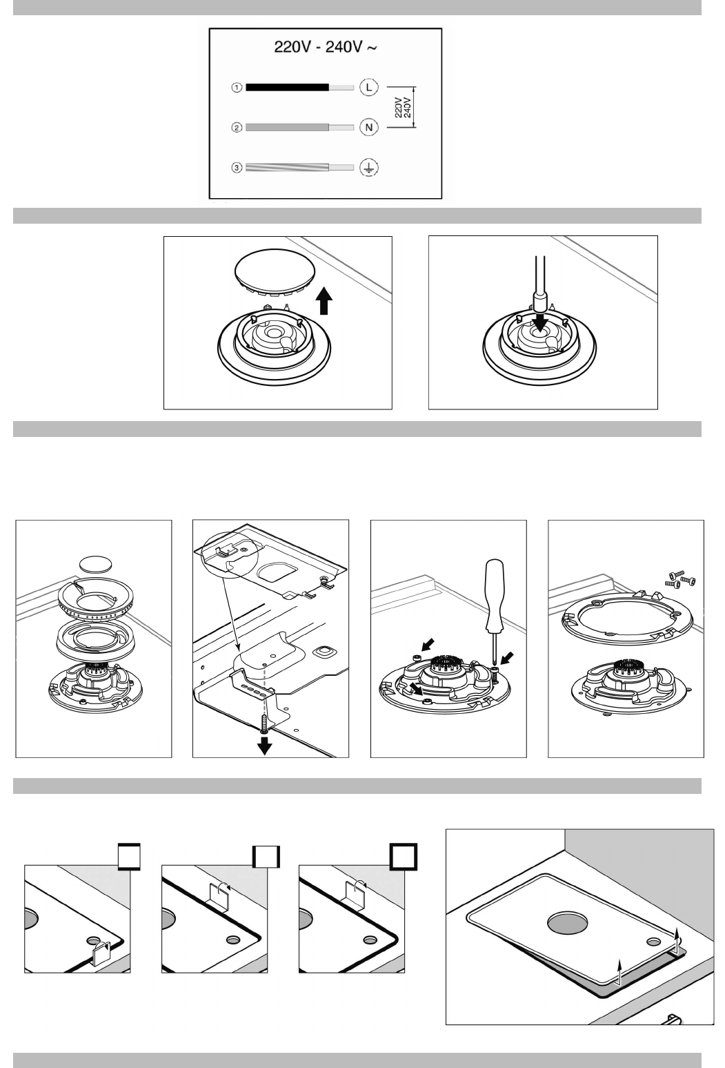
Монтаж прибора
Крепления и клеящаяся прокладка (по
нижнему краю варочной панели)
устанавливаются на фабрике, ни в коем
случае не снимайте их. Прокладка
гарантирует влагонепроницаемость всей
столешницы и препятствует фильтрации
влаги.
Чтобы закрепить варочную панель в
тумбе после того, как панель
установлена в рабочее положение, Вам
потребется раскрутить все крепления,
чтобы они свободно вращались
(откручивать их до конца не
обязательно).
Вставьте варочную панель в
подготовленное отверстие и выровняйте
ее.
Нажмите на края панели так, чтобы
варочная панель оперлась на край
столешницы по всему периметру.
Разверните крепления и туго затяните их.
Рис. 3.
Демонтаж варочной панели
Отсоедините прибор от электросети и от
газопровода.
Открутите винты креплений и повторите
действия, выполненные во время
монтажа, в обратном порядке.
Подключение газа (рис. 4)
На конце впускного патрубка варочной
панели имеется резьба диаметром 1/2”
(20,955 mm), позволяющая обеспечить:
- жесткое соединение.
- соединение с гибким металлическим
шлангом (L min. 1 m - max. 3 m). В этом
случае необходимо вставить между
концом входного патрубка и трубой
подачи газа дополнительную деталь
(427950) и герметичную прокладку
(034308), поставляемые с варочной
панелью. Рис. 4a.
В этом случае необходимо исключить
соприкосновение шланга с подвижными
частями мебели, в которую встраивается
варочная панель (например, с
выдвижными ящиками), а также
прохождение шланга в местах, которые
могут оказаться загроможденными.
Если необходимо сделать подводку газа
горизонтально, в нашем сервисном
центре можно приобрести колено трубы
с артикулом 173018, а также прокладку с
артикулом 034308. Рис. 4b.
Внимание! После внесения изменений в
соединительную конструкцию проверьте
ее герметичность.
Существует опасность утечки газа!
Производитель не несет ответственности
за утечку газа в соединениях,
выполненных пользователем или
исполителем монтажных работ.
Подключение к электросети
(рис. 5)
Проверьте, чтобы напряжение и
мощность прибора соответствовали
Вашей электросети.
Варочные панели поставляются с
кабелем питания, который может не
иметь штепсельной вилки.
Необходимо предусмотреть
размыкающее устройство для всех
полюсов прибора с воздушным зазором
между контактами не менее 3 мм (за
исключением случаев подсоединения с
использованием розетки, если
пользователь имее к ней доступ).
Приборы, снабженные штепсельной
вилкой, можно подключать только к
розеткам с правильно установленным
заземлением.
Данный прибор относится к классу “Y”:
не допускается замена кабеля питания
пользователем, это может делат только
сервисный центр. Необходимо учитывать
тип кабеля и его минимальное сечение.
Адаптация к другому виду
газа
Если это разрешено нормами Вашей
страны, данный прибор можно настроить
для использования с другими видами
газа (см. табличку с характеристиками).
Необходимые для этого детали находятся
в поставляемом с некоторыми моделями
наборе для адаптации, который также
можно приобрести в нашем сервисном
центре. Необходимо выполнть
следующие действия:
A) Замена жиклеров горелок
быстрой, полубыстрой и
вспомогательной конфорки
варочной панели (рис. 6):
- Снимите решетки, крышки горелок и
рассекатели.
- Замените жиклеры с помощью ключа,
имеющегося в продаже в нашем
сервисном центре (артикул 424699),
тщательно седя за тем, чтобы в процессе
снятия жиклера или его закрепления на
горелке он не соскочил.
Убедитесь в том, что жиклеры тщательно
прижаты, чтобы обеспечить
герметичность горелок. В данных
горелках е нужно производить
регулировку подачи первичного воздуха.
B) Замена жиклеров на горелках
конфорок двойного пламени
(рис. 7):
Блок стекла с профилями фиксируется
на варочной панели с помощью винтов и
креплений. Чтобы снять блок стека с
профилями, следуйте данным указаниям:
- Снимите все крышки горелок и решетки.
Рис. 7a.
- Высвободите переднюю деталь
крепления прибора к тумбе, вытащив
винт. Рис. 7b.
- Открутите винты горелок, рис. 7c-7d, и
вытащите ручки управления из их гнезд.
Используйте рычаг для демонтажа
483196, который можно приобрести в
нашем сервисном центре. Чтобы
отсоединить детали крепления в
передней части, воспользуйтесь рычагом
в точке, отмеченной на рисунке номер 8,
соответствующем модели Вашей
варочной панели.
Никогда не прикладывайте рычаг к
краям стеклянного блока, которые
не защищены профилем или рамой!
- Чтобы отсоединить детали крепления в
задней части панели, осторожно
поднимите блок стекла с профилями, как
это показано на рис. 8a.
Замена жиклера внешнего кольца
пламени (рис. 9a):
- Открутите крепежный винт, чтобы
сдвинуть втулку и получить доступ к
главному жиклеру. Рис. a1.
- Вытащите жиклер внешнего кольца
пламени, повернув его влево.
Рис. a2-a3.
- Закрутите новый жиклер внешнего
кольца пламени (рис. a3-a4), в
соответствии с таблицей II.
- Отрегулируйте расстояние до втулки
регулятора подачи воздуха L2 в
соответствии с параметром Z, указанным
в таблице II. Рис. a5.
- Закрутите крепежный винт. Рис. a6.
Замена жиклера внутреннего
кольца пламени (рис. 9b):
- Открутите деталь M3 от нарезной
детали M2. Для этого придерживайте
нарезную деталь, оказывая на нее
давлени в противоположном
направлении.
- Извлеките трубу из детали M2. Рис. b2.
- Открутите соединенные детали M2-M4
от детали M1. Рис. b3-b4.
- Извлеките жиклер внутреннего кольца
пламени M4 из детали M2. Рис. b5-b6.
- Закрутите новый жиклер внутреннего
кольца пламени M4, в соответствии с
таблицей II.
Рис. b6-b7.
Снова соберите все детали, повторив в
обратном порядке те же действия, что и в
процессе демонтажа.
Настройка кранов
Установите ручки управления в
положение минимального огня.
Снимите ручки кранов. Рис. 10.
Вы найдете уплотнительную прокладку из
эластичной резины. Для того, чтобы
открыть доступ к байпасному винту,
достаточно нажать на нее кончиком
отвертки. Рис. 10a.
Никогда не снимайте прокладку.
Если Вы не можете найти доступ к
байпасному винту, демонтируйте блок
стекла с профилями так, как это описан в
разделе Замена жиклеров на горелках
конфорок двойного пламени. Рис. 7.
Отрегулируйте минимальную величину
пламени, повернув байпасный винт с
помощью плоской отвертки.
В зависимости от вида газа, к которому
Вы адаптируете свой прибор (см. таблицу
III), выполните следующие действия:
A: закрутите регулировочные винты до
отказа.
B: ослабьте байпасные винты, пока газ не
будет правильно выходить из горелок:
убедитесь, чтобы при повороте ручки
управления от максимальной до
минимальной отметки горелки не гасли и
не происходило возврата пламени.
C: байпасные винты нужно заменить в
нашем сервисном центре.
D: никаких действий с байпасными
винтами производить не нужно.
Для обеспечения герметичности важно,
чтобы все уплотнительные прокладки
находились на своем месте. Эти
элементы необходимы для правильной
работы прибора, так как препятствуют
проникновению воды и грязи внутрь
варочной панели.
Снова установите ручки управления.
Никогда не демонтируйте вал газового
крана (Рис. 11). В случае его
повреждения замените весь кран.
Внимание! После окончания работы
наклейте рядом с таблицей с
характеристиками варочной панели
этикетку с казанием нового вида
газа.
I
G20, G25,
G110 (kW)
G25.1
(kW)
G20
(m3/h)
G25
(m3/h)
G25.1
(m3/h)
G30
(g/h)
G31
(g/h)
G110
(g/h)
6,00 - 0,572 0,665 - 435 428 - 0,8 W 220-240 V~ 50/60 Hz
4,70 - 0,448 0,521 - 341 335 - 0,8 W 220-240 V~ 50/60 Hz
6,00 - 0,572 0,665 - 435 428 - 0,8 W 220-240 V~ 50/60 Hz
4,70 - 0,448 0,521 - 341 335 - 0,8 W 220-240 V~ 50/60 Hz
6,00 - 0,572 0,665 - 435 428 - 0,8 W 220-240 V~ 50/60 Hz
4,70 - 0,448 0,521 - 341 335 - 0,8 W 220-240 V~ 50/60 Hz
6,00 5,80 0,572 0,665 0,642 435 428 - 0,8 W 220-240 V~ 50/60 Hz
6,00 - 0,572 0,665 - 435 428 - 0,8 W 220-240 V~ 50/60 Hz
4,70 4,70 0,448 0,521 0,520 341 335 - 0,8 W 220-240 V~ 50/60 Hz
6,00 5,80 0,572 0,665 0,642 435 428 - 0,8 W 220-240 V~ 50/60 Hz
4,70 4,70 0,448 0,521 0,520 341 335 1,070 0,8 W 220-240 V~ 50/60 Hz
4,70 - 0,448 0,521 - 341 335 1,070 0,8 W 220-240 V~ 50/60 Hz
4,70 4,70 0,448 0,521 0,520 341 335 1,070 0,8 W 220-240 V~ 50/60 Hz
6,00 5,80 0,572 0,665 0,642 435 428 - 0,8 W 220-240 V~ 50/60 Hz
4,70 4,70 0,448 0,521 0,520 341 335 - 0,8 W 220-240 V~ 50/60 Hz
Σ
Σ
Qn G30, G31, Qm
NL
Cat.
II
2L3B/P
25-30
p(mbar)
Cat.
Cat.
II
II
2E+3+
2H3B/P
20-50
20/25-28-30/37
AT
II
2H3B/P
20-30
LU
I
2E
20
II
2H3+
IT/PT
20-30/37
LV
I
2H
20
II
ES/GB/GR/IE
II
2H3+
20-28/37
PL
20-37
DE
II
2ELL3B/P
20-50
2E3P(B/P)
BE/FR
DK/FI/SE/CZ/SK/EE/LT/SI/RO/BG/NO/CY
p(mbar)
p(mbar)
BE/FR
Cat.
Cat.
II
2E+3+
20-50
AT
II
2H3B/P
20-30
II
2H3+
IT/PT
LV
I
2H
20
DE
20-50
II
2H3+
20-28/37
III
1a2H3B/P
DK
8-20-30
III
1ab2H3B/P
SE
8-20-30
ES/GB/GR/IE
FI/CZ/SK/EE/LT/SI/RO/BG/NO/CY
PL
I
20
2E
LU
20-37
20/25-28-30/37
II
II
20-30/37
II
2H3B/P
2ELL3B/P
2E3P(B/P)
p(mbar)
p(mbar)
Cat.
Cat.
II
II
2E+3+
2H3B/P
20-50
20/25-28-30/37
I
2E
20
AT
II
2H3B/P
20-30
ES/GR
II
2H3+
IT/PT
II
20-30/37
LV
I
2H
20
2ELL3B/P
II
20-28/37
20-50
PL
2H3+
20-37
2E3B/P
II
LU
BE/FR
DK/FI/SE/CZ/SK/EE/LT/SI/RO/BG/NO/CY
DE
p(mbar)
p(mbar)
AARDGAS G25/25 mbar
G-20/20 mbar ERDGAS / ERDGAS E /
NATURGAS / GAS NATURAL /
MAAKAASU NATURGAS / Φυοικ_αεοιο /
NATURAL GAS / GAS METANO / GAS
NATUREL / GAZ ZIEMNY
G-20/G-25-20/25 mbar AARDGAS / GAZ
NATUREL LACQ
G-20/20 mbar ERDGAS / ERDGAS E /
NATURGAS / GAS NATURAL /
MAAKAASU NATURGAS / Φυοικ_αεοιο /
NATURAL GAS / GAS METANO / GAS
NATUREL / GAZ ZIEMNY
G-20/G-25-20/25 mbar AARDGAS / GAZ
NATUREL LACQ
G-20/20 mbar ERDGAS / ERDGAS E /
NATURGAS / GAS NATURAL /
MAAKAASU NATURGAS / Φυοικ_αεοιο /
NATURAL GAS / GAS METANO / GAS
NATUREL / GAZ ZIEMNY
G-20/G-25-20/25 mbar AARDGAS / GAZ
NATUREL LACQ
II
III
Cod. 9000346853 N
distancia
casquillo
"Z" (mm)
G20 20 125 2,8 0,267 - - 39
G20 25 109 2,8 0,267 - - 39
G25 20 141 2,8 0,31 - - 39
G25 25 118 2,8 0,31 - - 39
G25.1 25 118 2,8 0,31 - - 39
G30 29 83 2,8 - 203 - 39
G30 37 82 2,8 - 203 - 38
G30 50 74 2,8 - 203 - 33
G31 37 83 2,8 - 200 - 39
G110 G120 8 278 2,8 0,638 - - 39
G20 20 93 1,9 0,181 - - 29
G20 25 91 1,9 0,181 - - 29
G25 20 105 1,9 0,211 - - 29
G25 25 104 1,9 0,211 - - 29
G25.1 25 104 1,9 0,21 - - 29
G30 29 70 1,9 - 138 - 29
G30 37 68 1,9 - 138 - 27
G30 50 60 1,9 - 138 - 25
G31 37 70 1,9 - 136 - 29
G110 G120 8 220 1,9 0,433 - - 29
G20 20 171 6 0,572 - 4 -
G20 20 69 - - - - 27
G20 25 163 6 0,572 - 4 -
G20 25 62 - - - - 27
G25 20 194 6 0,665 - 4 -
G25 20 76 - - - - 27
G25.1 25 180 5,8 0,642 - 4 -
G25.1 25 72 - - - - 27
G25 25 180 6 0,665 - 4 -
G25 25 72 - - - - 27
G30 29 115 6 - 435 11 -
G30 29 47 - - - - 27
G30 37 107 6 - 435 13 -
G30 37 44 - - - - 28
G30 50 100 6 - 435 5 -
G30 50 42 - - - - 25
G31 37 115 6 - 428 11 -
G31 37 47 - - - - 27
m3/h
gas
mbar
Qn (kW)
g/h
G20/20 G20/25 G25/20 G25/25 G25.1/25 G30/29 G30/37 G30/50 G31/37 G110-G120/8
G20/20
D D D D A C C A B
G20/25
D D D D A C C A B
G25/20
D D D D A C C A B
G25/25
D D D D A C C A B
G25.1/25
D D D D A C C A B
G30/29
B B B B B C C D B
G30/37
C C C C C C C C C
G30/50
C C C C C C C C C
G31/37
B B B B B D C C B
G110-G120/8
B B B B B A C C A
16

Hulp nodig? Stel uw vraag in het forum

Spelregels

Misbruik melden

Gebruikershandleiding.com neemt misbruik van zijn services uitermate serieus. U kunt hieronder aangeven waarom deze vraag ongepast is. Wij controleren de vraag en zonodig wordt deze verwijderd.

Product:

Bijvoorbeeld antisemitische inhoud, racistische inhoud, of materiaal dat gewelddadige fysieke handelingen tot gevolg kan hebben.

Bijvoorbeeld een creditcardnummer, een persoonlijk identificatienummer, of een geheim adres. E-mailadressen en volledige namen worden niet als privégegevens beschouwd.

Spelregels forum

Om tot zinvolle vragen te komen hanteren wij de volgende spelregels:

Belangrijk! Als er een antwoord wordt gegeven op uw vraag, dan is het voor de gever van het antwoord nuttig om te weten als u er wel (of niet) mee geholpen bent! Wij vragen u dus ook te reageren op een antwoord.

Belangrijk! Antwoorden worden ook per e-mail naar abonnees gestuurd. Laat uw emailadres achter op deze site, zodat u op de hoogte blijft. U krijgt dan ook andere vragen en antwoorden te zien.

Abonneren

Abonneer u voor het ontvangen van emails voor uw Bosch PRB326B70N bij:


U ontvangt een email met instructies om u voor één of beide opties in te schrijven.


Ontvang uw handleiding per email

Vul uw emailadres in en ontvang de handleiding van Bosch PRB326B70N in de taal/talen: Nederlands, Duits, Engels, Frans, Italiaans, Portugees, Spaans, Turks als bijlage per email.

De handleiding is 2,39 mb groot.


U ontvangt de handleiding per email binnen enkele minuten. Als u geen email heeft ontvangen, dan heeft u waarschijnlijk een verkeerd emailadres ingevuld of is uw mailbox te vol. Daarnaast kan het zijn dat uw internetprovider een maximum heeft aan de grootte per email. Omdat hier een handleiding wordt meegestuurd, kan het voorkomen dat de email groter is dan toegestaan bij uw provider.

Stel vragen via chat aan uw handleiding

Stel uw vraag over deze PDF

Andere handleiding(en) van Bosch PRB326B70N

Bosch PRB326B70N Gebruiksaanwijzing - Nederlands - 15 pagina's


Uw handleiding is per email verstuurd. Controleer uw email

Als u niet binnen een kwartier uw email met handleiding ontvangen heeft, kan het zijn dat u een verkeerd emailadres heeft ingevuld of dat uw emailprovider een maximum grootte per email heeft ingesteld die kleiner is dan de grootte van de handleiding.

Er is een email naar u verstuurd om uw inschrijving definitief te maken.

Controleer uw email en volg de aanwijzingen op om uw inschrijving definitief te maken

U heeft geen emailadres opgegeven

Als u de handleiding per email wilt ontvangen, vul dan een geldig emailadres in.

Uw vraag is op deze pagina toegevoegd

Wilt u een email ontvangen bij een antwoord en/of nieuwe vragen? Vul dan hier uw emailadres in.


Info