All rights reserved. Distributed by BRK Brands, Inc. 3901 Liberty Street Road, Aurora, IL 60504-8122. Due to continuing product development, the
product inside the packaging may look slightly different than the one on the package.
BRK Brands, Inc. is a subsidiary of Jarden Corporation (NYSE: JAH). First Alert® is a registered trademark of the First Alert Trust. To obtain warranty
service, contact the Consumer Affairs Division at 1-800-323-9005, Monday through Friday, 7:30 a.m. - 5 p.m., Central Standard Time.
Made in China
Page 3
introduction
key product features
Main Description
Sixteen channel H.264 digital video recorder with Internet remote surveillance,
motion detection, PTZ and alarm control suitable for applications such as high-
end residential - new or remodel, light commercial, small business/retail, small
warehouse or small grocery.
Product features
•H.264 Compression & Virus free Linux O/S
•Real hexaplex operation - simultaneous record, playback, mobile phone live
•User-friendly interface: 16 bit true color, semi-transparent GUI with notes for
selected menu items
•Advanced motion detection activated recording
•24/7 Scheduled Recording
•Network monitoring through internet access
•Supports USB or external DVD backup
•Hi-speed backup/upgrade/record via USB2.0
•PTZ camera control
Page 4
sectiondescription
Page
number
1
Introduction2-3
2
Safety6
3
Product Overview7
What is in the Box7
DVR Controls
Front Panel8
Back Panel9
Remote Control10
Mouse Controls11
Camera Power Connections12
Connecting Devices12
4
Initial Setup - System Operation13
System Start Up13
Default Video Output13
Power On/Off13
User Login13
Live View Screen14
Quick Access Menu14
Main Menu Access14
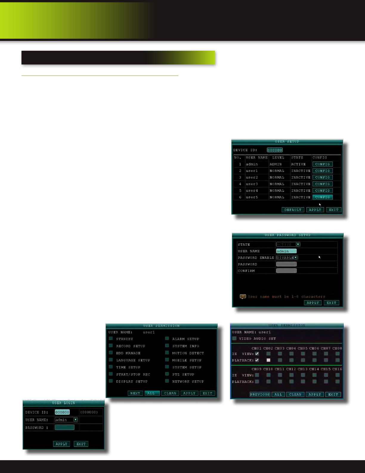
Password Setup and User Permissions15
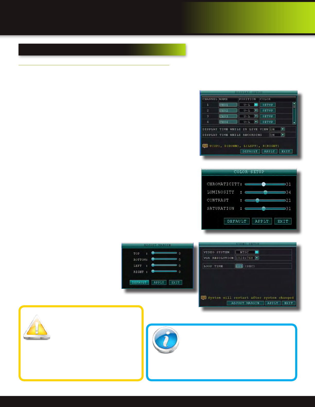
Camera Display Setup16
Display, Video/Audio16
Language, Date and Time17
Language, Date/Time and Daylight Savings Time (DST)17
5
Basic Operation18
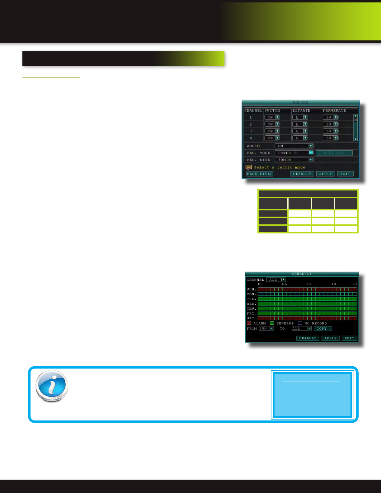
Recording18
Configure Recording Options18
Recording Schedule (Timer Recording)18
Recording Schedule (TIMER RECORD) Example19
Privacy Mask Field19
Motion Detect Setup19
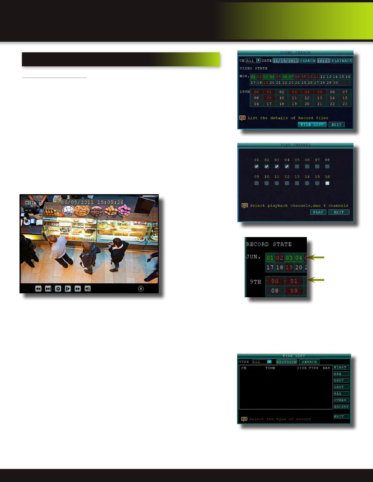
Playback20
Playback and Record Search20
On-Screen Playback Controls20
File List21
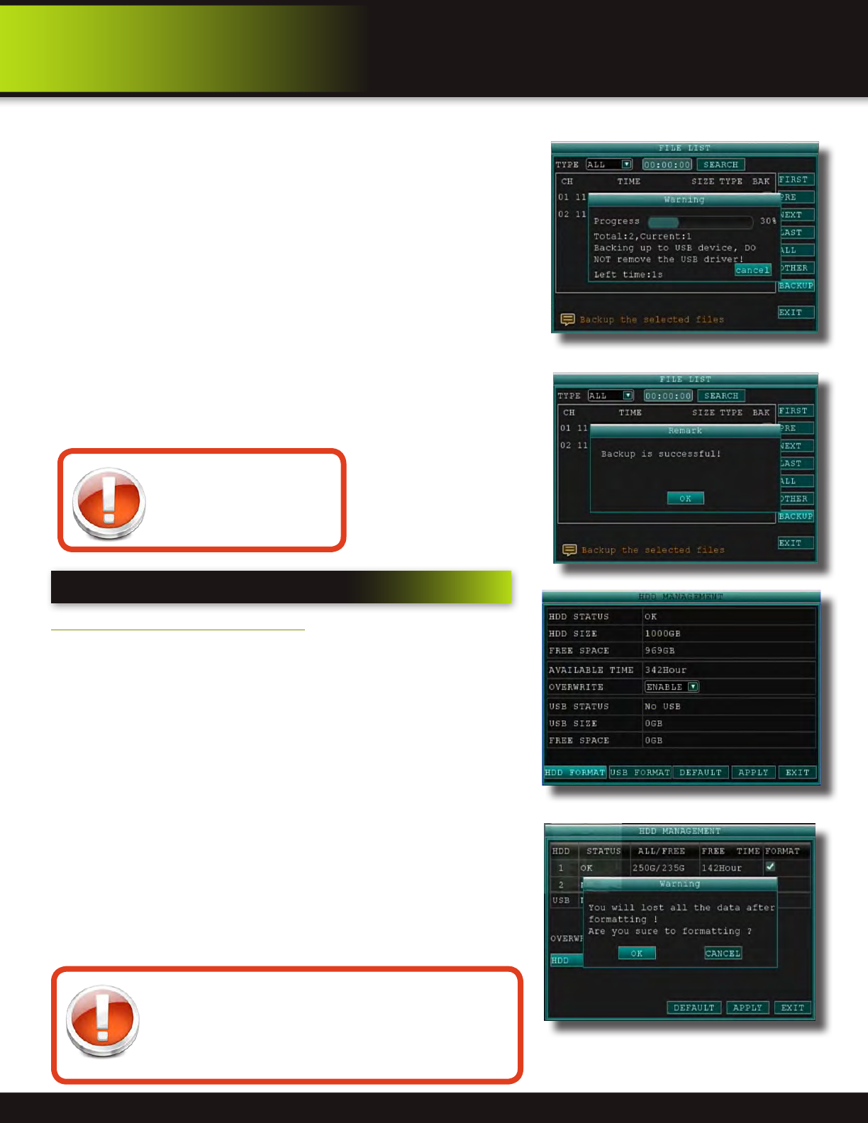
Backup21
HDD Management 21-22
introduction
table of contents
Page 5
introduction
table of contents
sectiondescription
Page
number
6
Advanced Operation22
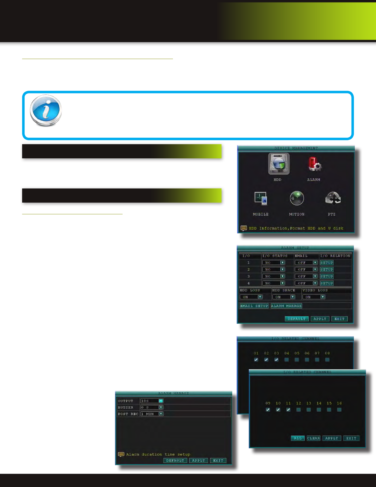
Alarm22-23
Alarm Setup22-23
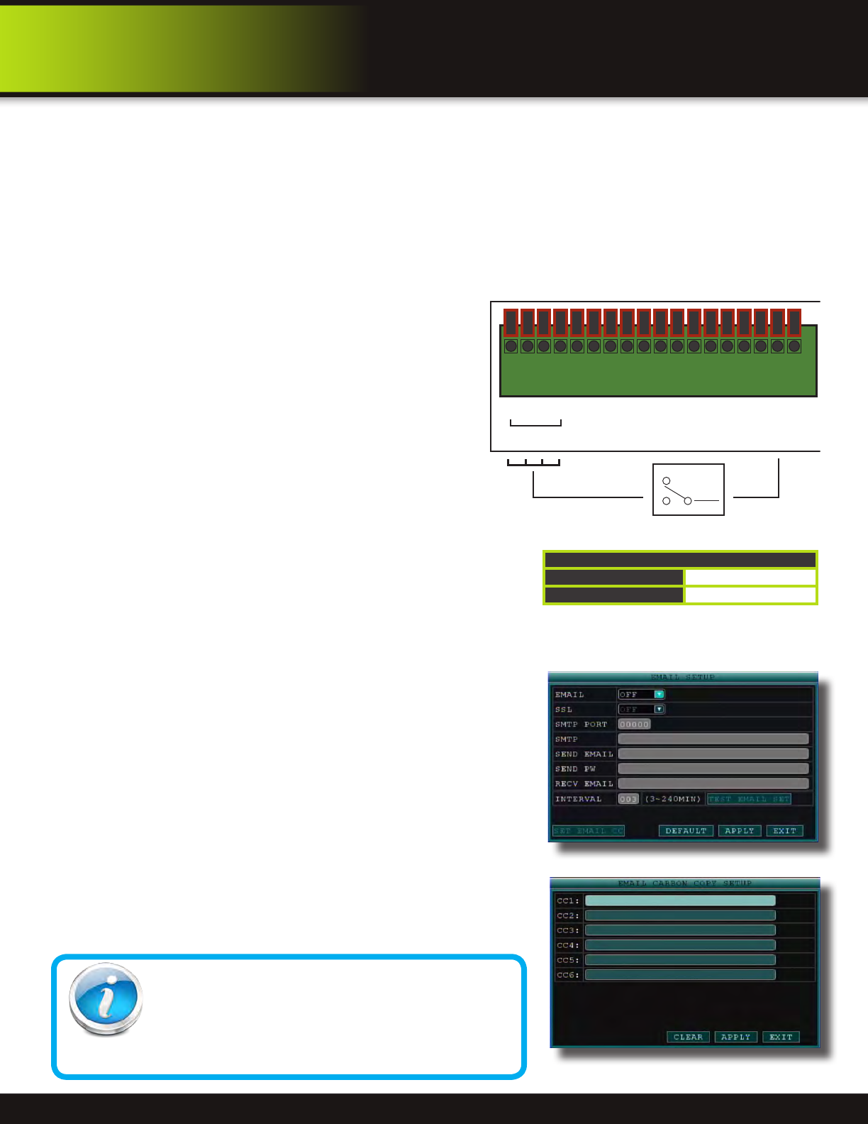
E-mail Setup23
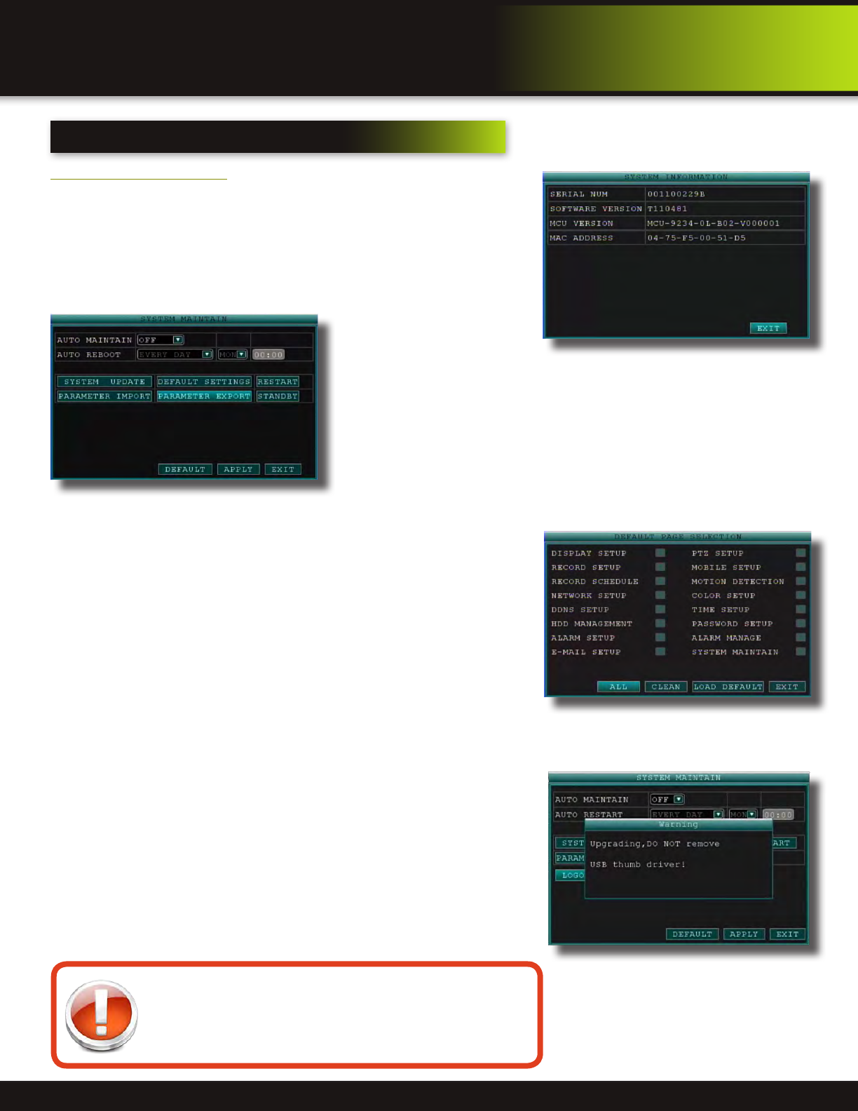
System Info and System Update24
System Maintain24
Upgrade Firmware24
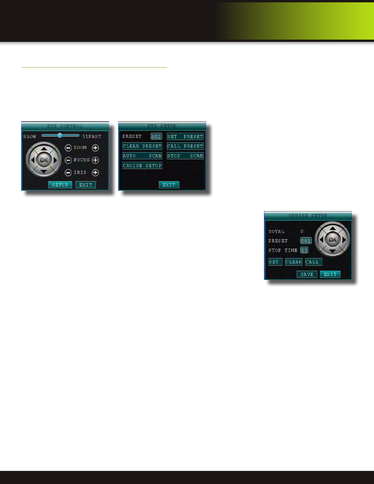
PTZ Setup and Control25-26
Step 1: Connect your PTZ Camera to this DVR25
Step 2: Configure PTZ Communication Settings25
Step 3: Configure the Operation and Control of your PTZ Camera(s)25
Step 4: Configure the CRUISE SETTING of your PTZ Camera26
7
Remote Access27
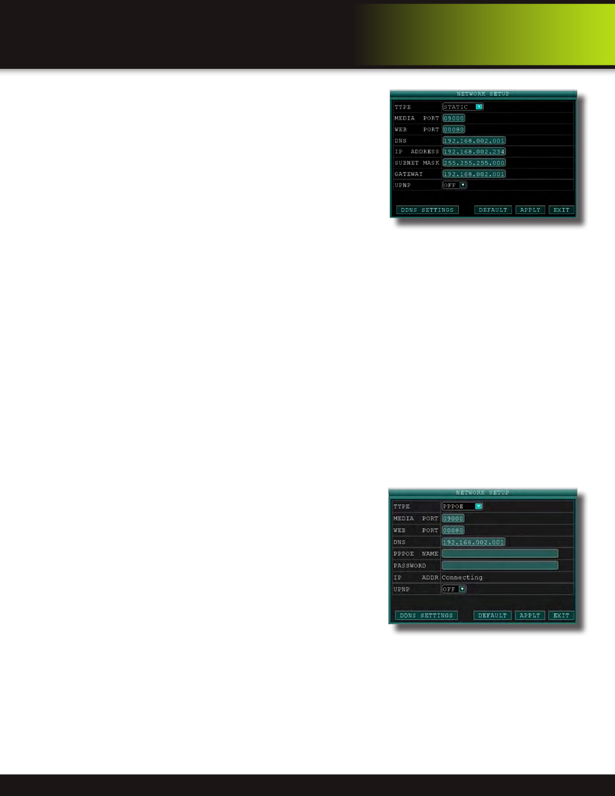
Network Setup for Remote Access27
DHCP (Dynamic Host Configuration Protocol)27
Static IP27
UPnP (Universal Plug and Play)28
PPPoE (Point-to-Point Protocol Over Ethernet)28
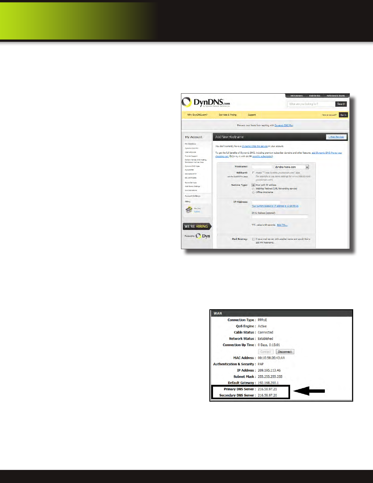
DDNS (Dynamic Domain Name Service29-30
Port Forwarding30-32
Remote Surveillance33
Remote Surveillance using Internet Explorer 833-34
Using Remote Surveillance34
Remote Surveillance Main Screen35
Live Viewing Tab36
Playback Tab37-38
Setup Tab39
Setting, Maintenance and Host Info Tabs40
8
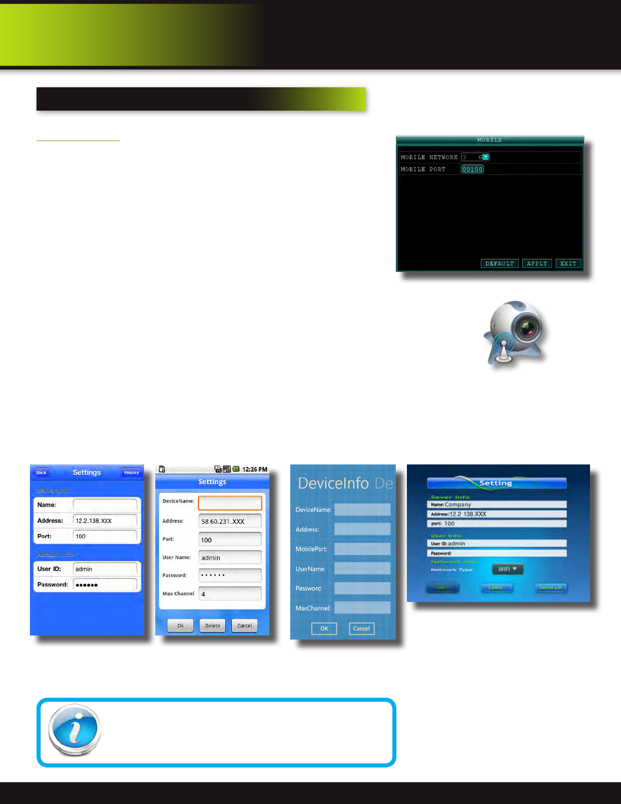
Mobile Phone41
Mobile Setup41
Windows Mobile Pro (6.0 or later) OS Phones
41-42
Symbian (S60 3rd or later) OS Phones
43-44
Android 1.5 Mobile OS Phones
45-46
Apple iPhone on 3G Networks OS Phones
47
Blackberry OS 5.0 Phones (Curve 8900, Bold 9700, Tour 9630)
48-49
9
Appendix50
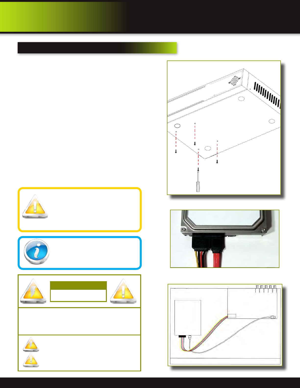
Hard Drive Removal and Installation50
Specifications51
FAQ’s (Frequently Asked Questions)52-53
Troubleshooting54
Warranty55
Page 6
safety
caution statements
CAUTION: TO REDUCE THE RISK OF ELECTRIC SHOCK.
UNPLUG ALL POWER SOURCES, INCLUDING CAMERAS FROM
THE DVR BEFORE REMOVING COVER. FAILURE TO DO SO CAN
RESULT IN DAMAGE TO THE DVR OR ITS COMPONENTS AS
WELL AS INJURY OR DEATH.
The lightning ash with arrowhead symbol, within an equilateral
triangle, is intended to alert the user to the presence of un-insulated
“dangerous voltage” within the product’s enclosure that may be of
sufcient magnitude to constitute a risk of electric shock.
The exclamation point within an equilateral triangle, is intended to
alert the user to the presence of important operating and maintenance
(servicing) instructions in the literature accompanying the appliance.
WARNING: TO PREVENT FIRE OR SHOCK HAZARD, DO NOT
EXPOSE THIS UNIT TO RAIN OR MOISTURE
CAUTION: TO PREVENT ELECTRIC SHOCK, MATCH WIDE
BLADE OF THE PLUG TO THE WIDE SLOT AND FULLY INSERT
CAUTION
RISK OF ELECTRIC SHOCK
safety precautions
•Do not drop, puncture, or disassemble the DVR.
•Do not tug on the power adapter. Use the plug to remove it from the wall.
•Do not expose the DVR to high temperatures.
•For your own safety, avoid using the DVR when there is a storm or lightning in your area.
•Use the DVR with care. Avoid pressing hard on the DVR body.
•Do not crush or damage the power cable.
FCC Compliance Class B Digital Device
This equipment has been tested and found to comply with the limits for a Class B digital device, pursuant to Part 15 of the FCC rules. These limits are
designed to provide reasonable protection against harmful interference in a residential installation. This equipment generates, uses and can radiate
radio frequency energy and, if not installed and used in accordance with the instructions, may cause harmful interference to radio communications.
However, there is no guarantee that the interference will not occur in a particular installation. If this equipment does cause harmful interference to radio
or television reception, which can be determined by turning the equipment off and on, the user is encouraged to try to correct the interference by one
or more of the following measures:
•Reorient or relocate the receiving antenna.
•Increase the separation between the equipment and receiver.
•Connect the equipment into an outlet on a circuit different from that of the receiver.
•Consult the dealer or an experienced radio or TV technician for help.
Notice: Only peripherals complying with FCC class B limits may be attached to this equipment. Operation with non-compliant peripherals or
peripherals not recommended by First Alert / BRK Brands, Inc. is likely to result in interference to radio and TV reception. Changes or modications to
the product, not expressly approved by First Alert / BRK Brands, Inc., could void the user’s authority to operate the equipment.
Important: The information shown in the FCC Declaration of Conformity paragraph below is a requirement of the FCC and is intended to supply you
with information regarding the FCC approval of this device. The phone number listed below is for FCC related questions only and not intended for
questions regarding the connection or operation for this device.
FCC Declaration of Conformity for devices with the FCC logo. Responsible Party: First Alert / BRK Brands, Inc., 3901 Liberty Street Rd.,
We, First Alert / BRK Brands, Inc. declare under our sole responsibility that the device to which this declaration relates: Complies with Part 15 of the
FCC Rules. Operation is subject to the following two conditions: (1) this device may not cause harmful interference, and (2) this device must accept
any interference received, including interference that may cause undesired operation.
FCC Certification (if applicable)
This device contains a radio transmitter. Accordingly, it has been certied as compliant with 47 CFR Part 15 of the FCC Rules for intentional radiators.
Products that contain a radio transmitter are labeled with an FCC ID.
fcc compliance
These symbols indicate that it is prohibited to
dispose of these batteries in the household
waste. Take spent batteries that can no longer
be charged to the designated collection points
in your community.
disposal
fire and electric shock hazard statement
Caution!
When working with electrostatic sensitive de-
vices such as hard disk or DVR unit, make sure
you use a static-free workstation. Any electro-
static energy coming in contact with the hard
disk or DVR can damage it permanently.
Page 7
product overview
package contents
What
,
s in the box
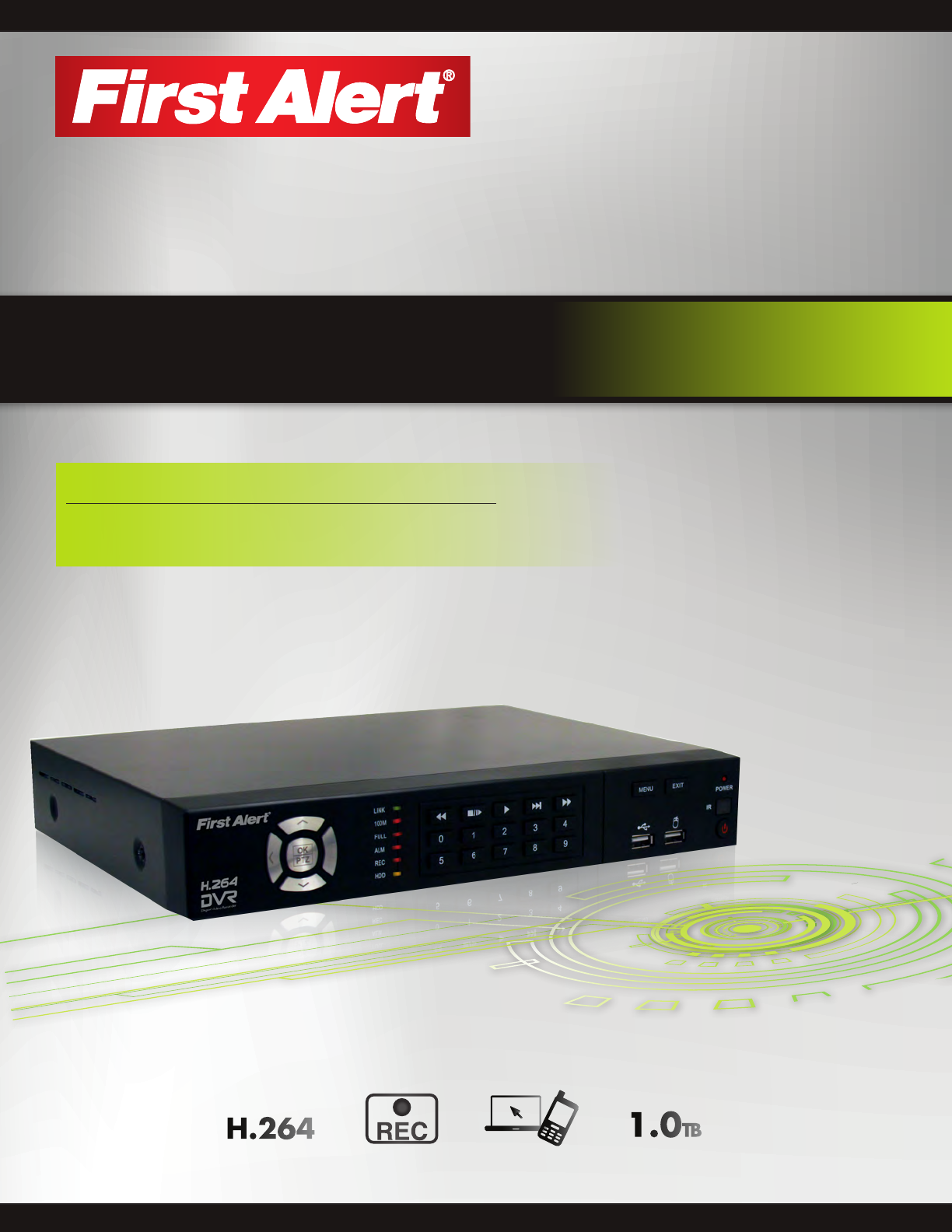
PRO-D1610 H.264
16 Channel Digital DVR
with 1TB Hard Drive
USB 2.0 Mouse
WARNING
PROTECTED BY
THESE PREMISES ARE UNDER
24 HOUR VIDEO SURVEILLANCE
2 Window
Warning Decals
Installation Software
and Manuals
Power Supply for DVR
RJ45 Ethernet Cable
(cable color may be different)
H.264 Digital DVR
quick install guide
MODELS
PRO-D1610 16 Channel
VIDEO
COMPRESSION
DIGITAL DVR
RECORDER
MOBILE PHONE/
WEB READY
H.264
BRK Series
DVR OPTIMIZED
SATA HDD
1.0TB
Quick Install Guide
Remote Control
Page 8
product overview
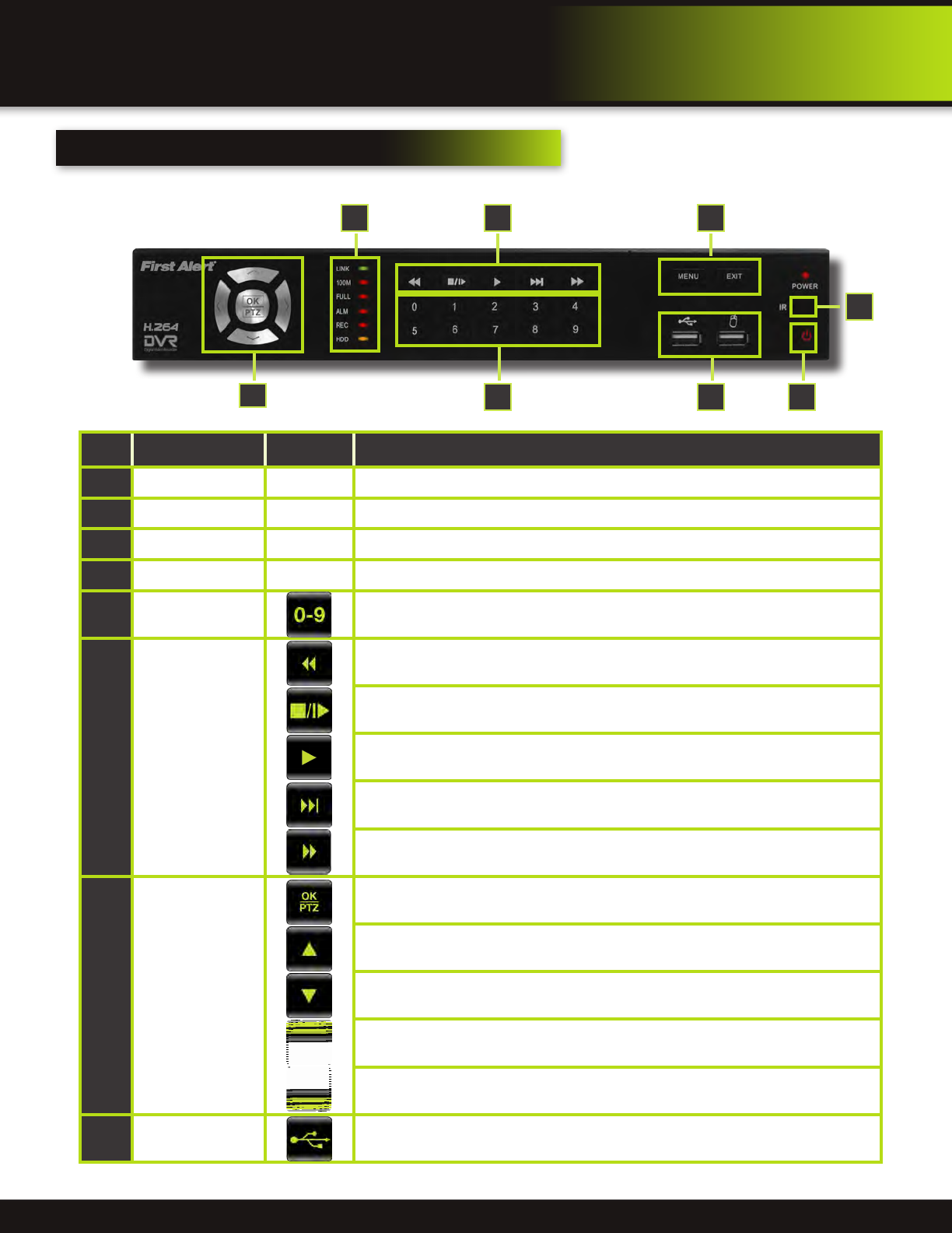
dvr controls
ItemFunctionControlDescription
1
StandbyPress to enter/exit standby mode
2
IR SensorIR receiver for the remote control
3
MENU/EXITPress to open/close the main menu
4
LED IndicatorsShows status of Link, 100M, Full, Alarm, Record, HDD.
5
Channel Numbers
Press buttons 1~9 to view the selected channel in full-screen. To display 2-digit channels
press both buttons slowly. Pressing 0 returns screen to 16 camera display mode.
6
During playback,
press the following:
Increase reverse playback speed 2X, 4X, 8X
Press to freeze playback to one frame, then press again to advance frame-by-frame
Press to start playback
Press to slow playback speed by 1/2, 1/4, 1/8
Press to increase forward playback speed 2X, 4X, 8X
7
Navigation/OK/PTZ
(Select direction
arrow, then press OK
to start PTZ motion)
In menus, press to confirm selections; in PTZ mode, press to change the navigation but-
tons to control the connected PTZ camera (not included)
Press to move cursor up; in PTZ mode, press to pan camera up
Press to move cursor down; in PTZ mode, press to pan camera down
Press to move cursor left; in PTZ mode, press to pan camera left
Press to move cursor right; in PTZ mode, press to pan camera right
8
USB
Connect a USB flash drive to the left port for data backup and firmware upgrades. Con-
nect a USB mouse to the right port
Front Panel
2
1
7
6
5
43
8
Page 9
product overview
dvr controls
back Panel
ItemFunctionDescription
1
POWER InputDC 12V/3A power connection
2
NetworkFor connecting RJ45 ethernet cable to PC or router
3
VGA OutputFor connecting to a VGA monitor
4
Video OutputFor connecting to a BNC monitor (800 x 600) - NTSC or PAL
5
Alarm Input4 alarm inputs
Alarm Output2 alarm outputs
RS485For connecting PTZ cameras
+12V
Power supply for alarm block inputs, the current is 100mA (to prevent
short circuits)
6
Audio Input
For connecting audio signal from audio capable cameras or self powered
microphones (RCA jacks)
7
Audio OutputFor connecting audio signal to amplified speakers (RCA jacks)
8
Video InputFor connecting video signal from cameras (BNC)
9
FanCooling fan
10
GroundGround connection
216543
9
7
810
Page 10
7
2
1
11
6
54
3
8
9
10
9
12
13
product overview
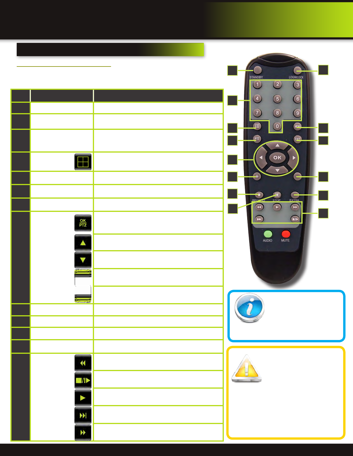
remote control
Remote Control
TIP: When using the remote
control to enter password
and camera titles, select the
field using the navigation
buttons, press OK, and then press the num-
ber buttons.
Battery Replacement -
Instructions for Use
Always purchase the correct
size and grade of battery most
suitable for intended use. Re-
place all batteries of a set at
the same time. Clean the battery contacts
and also those of the device prior to battery
installation. Ensure the batteries are installed
correctly with regard to polarity (+ and -). Re-
move batteries from equipment that is not to
be used for an extended period of time. Re-
move used batteries promptly.
remote control
Remote Control Operation
The remote control is the secondary input device for navigating the system’s
interface. In device operation, the OK key has the same function as “left click” of
the mouse.
ItemFunctionDescription
1
STANDBYPress to turn standby mode ON/OFF
2
LOGIN/LOCK
If “Security” has been enabled in the setup menu, press to
open the user password login screen or log off system.
3
Number/Channel Buttons
Press buttons 1~9 to view the selected channel in full-
screen. To display 2-digit channels press both buttons
slowly. Pressing 0 returns screen to 16 camera display.
4
Window
Display
Toggle between split-screen displays: Channels 1-4, 5-8,
9-12, 13-16, 1-9, 8-16, 1-16
5
MENUOpens the main menu
6
PTZPress to open the PTZ control window
7
EXITClose menu windows
8
Navigation/OK
(Select direction
arrow, then press
OK to start PTZ
motion)
In menus, press to confirm selections; in PTZ mode, press
to change the navigation buttons to control the connected
PTZ camera (not included)
Press to move cursor up; in PTZ mode, press to pan
camera up
Press to move cursor down; in PTZ mode, press to pan
camera down
Press to move cursor left; in PTZ mode, press to pan
camera left
Press to move cursor right; in PTZ mode, press to pan
camera right
9
+ / -In menus, press to adjust values
10
RECORDPress to start manual recording
11
STOPPress to stop manual recording
12
EXTRAFor future use
13
Playback
Controls
Increase reverse playback speed 2X, 4X, 8X
Press to freeze playback to one frame, then press again to
advance frame-by-frame
Press to start playback
Press to slow playback speed by 1/2, 1/4, 1/8
Press to increase forward playback speed 2X, 4X, 8X
Page 11
pRODUCT oVERVIEW
MOUSE and virtual Keypad
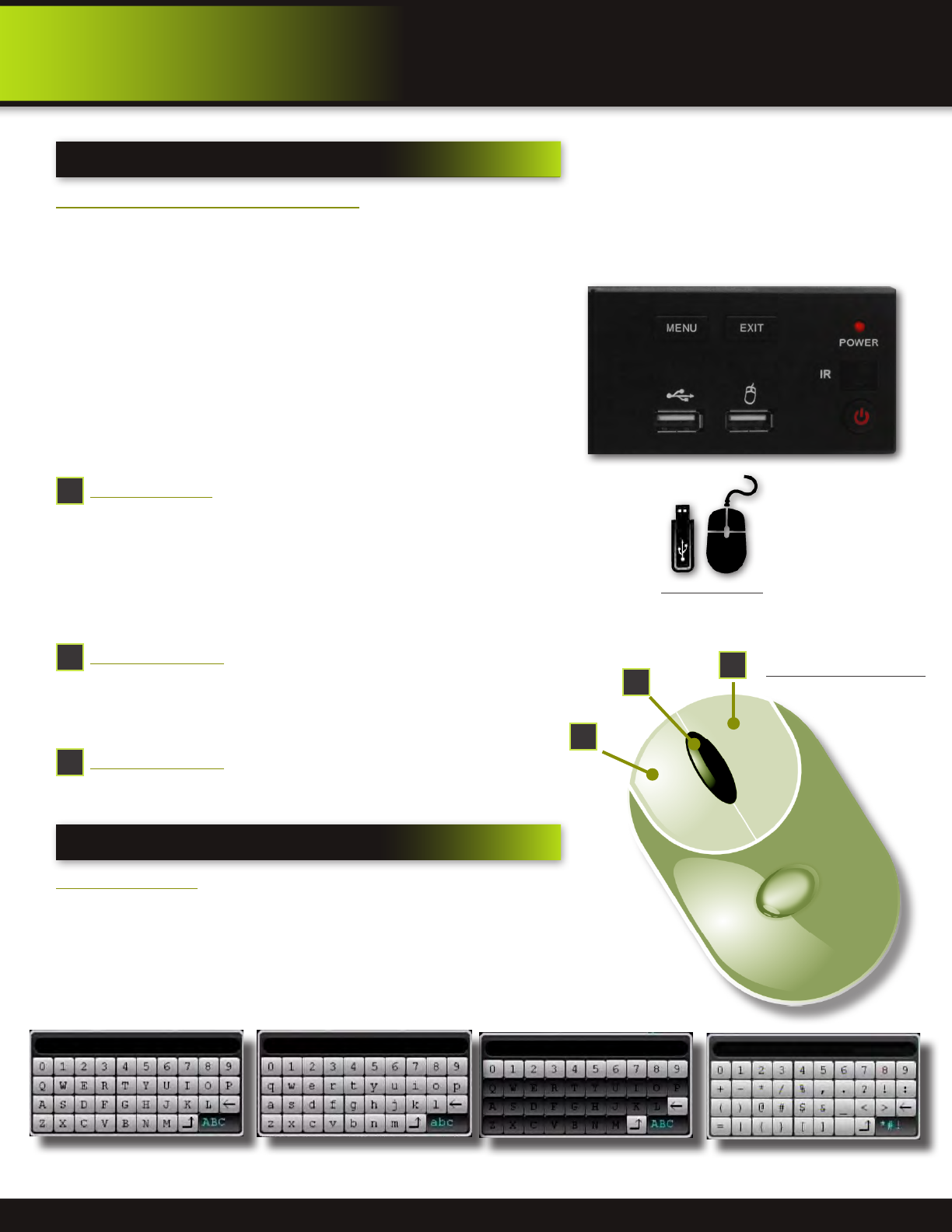
Mouse Operation with this DVR
The mouse is the primary input device for navigating system
menus.
NOTE: Unless otherwise noted, all system functions described in
this manual are achieved through mouse input.
To use a mouse with the system:
Connect a USB mouse to the USB MOUSE port on front panel of
the system.
NOTE: Only the USB 2.0 port on the front panel is designed for
data backup to a USB flash drive. Do not connect a USB flash
drive to the USB MOUSE port.
Use the mouse buttons to perform the following:
1
Left-Button:
•Click to select a menu option
•During live viewing in split-screen double-click on a
channel to view the selected channel in full-screen
•Double-click the channel again to return to split-screen
view
•Selecting letter or number on the virtual keypad
2
Right-Button:
•Click to open the Quick Access Menu
•Exits any window
•Exits any menu or re-opens previous menu
3
Scroll-Wheel:
•Forward-switch to VGA; backward-switch to BNC (CVBS)
MOUSE controls
DVR Front Face
Connect Mouse &
USB Drive
2
1
Mouse Button Operation
3
Virtual Keypad
Virtual Keypad
To enter text or numerical data, the system uses a virtual
keypad. In fields where letters or numbers can be entered,
you can switch between various formats – numbers, numbers
& symbols, upper case (ABC) and lower case (abc). Note you
can access all numbers when in the “Letters” virtual keypads.
See below.
Numbers
Letters-Uppercase
Letters-Lowercase
Numbers & Symbols
Page 12
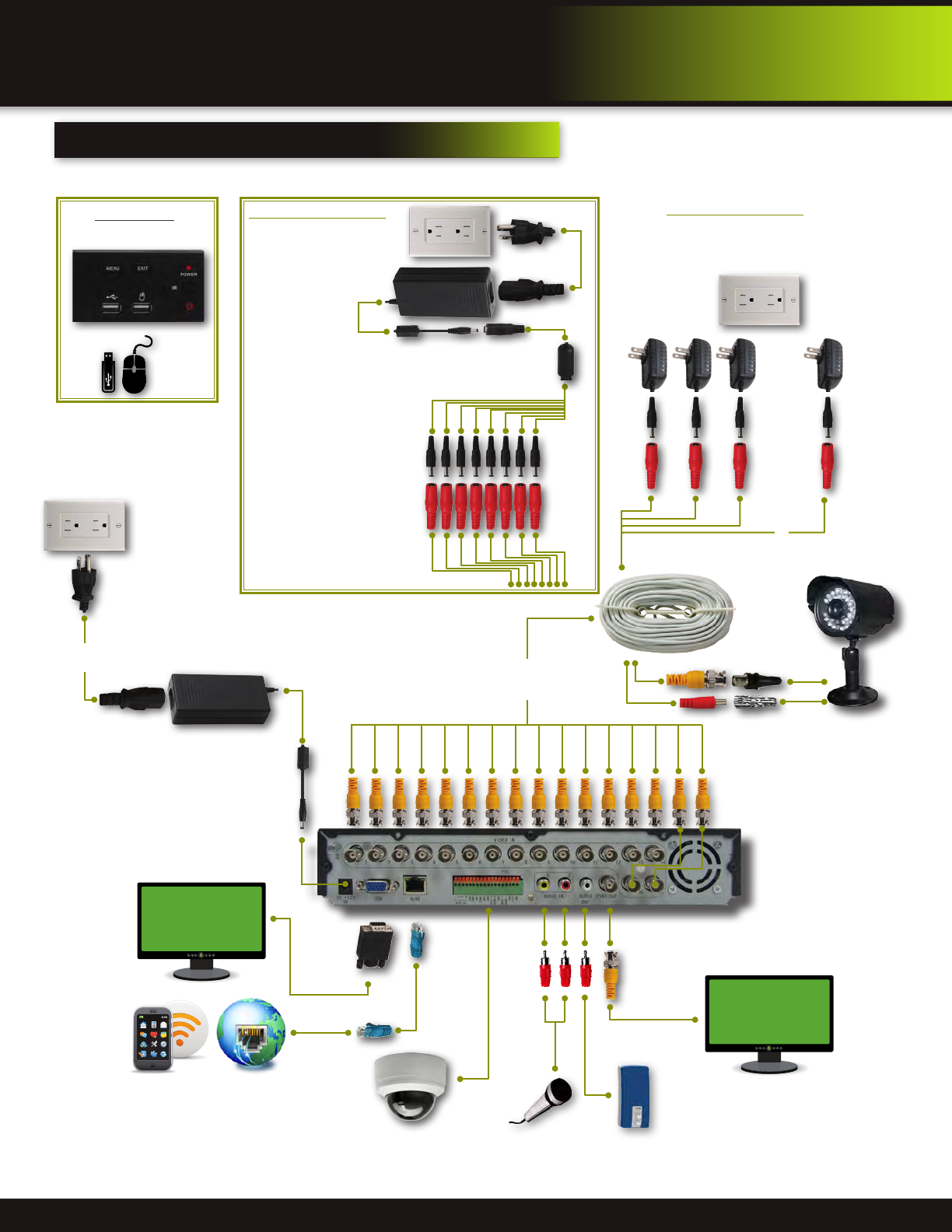
connecting devices
Video to Camera
Power to Camera
Power to 1 to 16 Cameras
VGA to PC Monitor or TV
(Monitor and Cable Not included)
RJ45 Ethernet
to Router and
Internet
PTZ & Alarm Connections
(Cameras not included)
Follow this diagram to make device connections. This diagram is for illustration purposes only. Cabling and other accessories
shown are not included with this DVR unless indicated. See “What’s in the Box” for included devices.
Power to DVR
Power
from 120V
DC Converter - 12V
(included with this DVR)
DVR Front Face
Connect Mouse &
USB Drive
product overview
cAMERA AND pOWER cONNECTIONS
Smartphone
through Mobile
Internet Setup
(Smartphone Not
included)
RCA Audio In from
2 Audio Cameras or
Powered Microphone
(Not included)
Powering Cameras
Power from each Camera Adaptor
that came with your camera.
Not included
RCA Audio Out to
Powered Speakers
(Not included)
To each DVR
Channel 1-16
BNC to Security Camera Monitor
(Monitor and Cable Not included)
BNC Video/DC Power Cable:
(1 per Camera). Note: Cables ,
Power Adaptors and Cameras
not included
Power
from 120V
~
~
DC Converter - 12V
Power
from 120V
12V DC
Converter
Powering Cameras
Power from a single
Power Adaptor and 8-way
splitter. 2 required.
Not included.
Splitter -
8 camera
Power to Cameras
Note: To reduce the number of
single camera power adaptors
required, you may be able to
use a larger power adaptor
(3A or 5A) and a splitter cable.
Contact your local security
camera accessories dealer
for help in matching splitter,
cable, camera and power
adaptor requirements.
Page 13
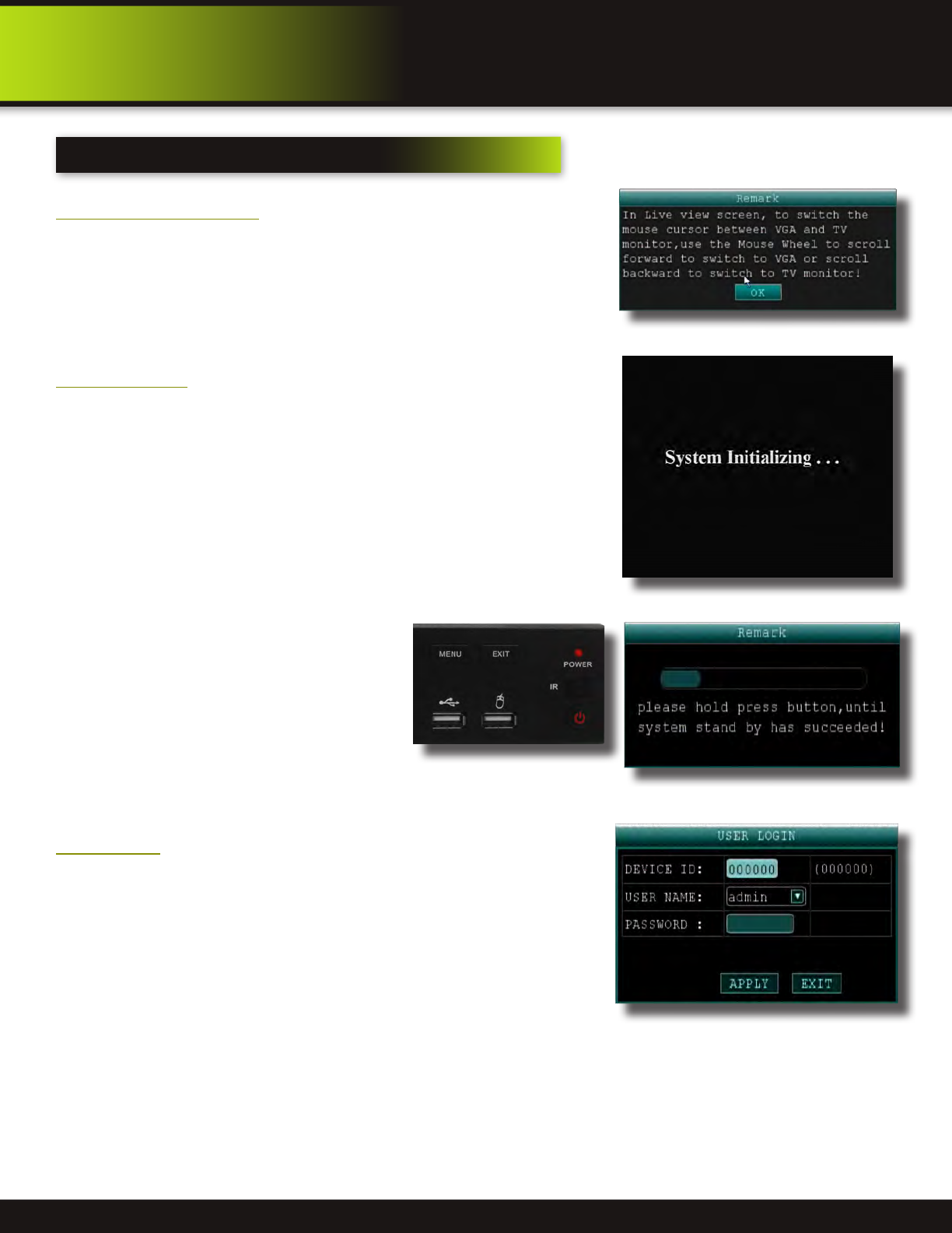
system start up
Default Video Output
The default video output for the DVR system is VGA. If you connect a BNC (CVBS)
monitor on initial setup, you will need to use the mouse “Scroll Wheel” to switch to
the BNC output to be able to use the mouse. Roll the mouse “Scroll Wheel” back-
ward to go to BNC and forward to go to VGA. The REMARK screen is shown on
startup.
Power On/Off
To power the system On/Off, connect the power cable to the DC 12V port on the rear
panel. At startup, the system performs a basic system check and runs an initial loading
sequence. After a few moments, the system loads a live display view.
Standby Mode
The system can also be put into Standby Mode.
Power will remain to the system but will not be
recording. To start/stop Standby Mode:
1. Press and hold the POWER button on the
front panel or the STANDBY button on the
remote control until the prompt closes. The
system enters standby mode. You can also
enter Standby mode through the Quick
Access Menu. See next page.
2. To exit standby mode, press and hold the
POWER button on the front panel or remote
control until the system beeps. The system will begin powering up.
User Login
Password
ATTENTION: By default, passwords are disabled on the system. You do not need
to enter a password when accessing any system menus. However, for security
purposes, it is highly recommended to enable passwords on the system using
the Password Menu. See “Password” section for details on setting up passwords.
Click APPLY to access the menus or click EXIT to cancel password setup and
return to the LIVE VIEW screen.
Switch between VGA to BNC Output
initial setup
system operation
Standby Mode
User Login Menu
Power/Standby Switch
Page 14
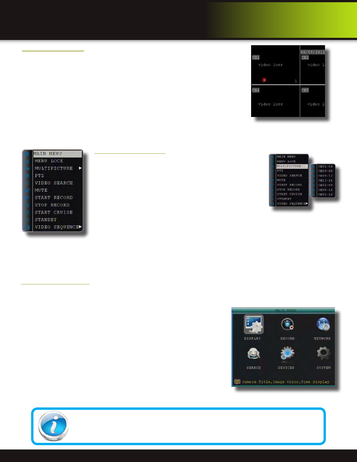
Main Menu Access
To open the Main Menu: Right-click anywhere on-screen to open the Quick Access Menu and select MAIN MENU (mouse only), or
press the MENU button on the remote control or front panel of the system.
NOTE: If passwords are enabled on the system, you need enter the 1-8 digit numerical password to open the Main Menu.
Main Menu
1. DISPLAY: Configure Display Setup
2. RECORD: Configure recording parameters (quality, resolution), set record
modes, and enable/disable audio recording. Note: Audio capable cameras
(not included) are required for audio recording on the system.
3. NETWORK: Configure Network Setup
4. SEARCH: Search for recorded video on the system.
Gebruikershandleiding.com neemt misbruik van zijn services uitermate serieus. U kunt hieronder aangeven waarom deze vraag ongepast is. Wij controleren de vraag en zonodig wordt deze verwijderd.
Product:
Spelregels forum
Om tot zinvolle vragen te komen hanteren wij de volgende spelregels:
lees eerst de handleiding door;
controleer of uw vraag al eerder door iemand anders is gesteld;
probeer uw vraag zo duidelijk mogelijk te stellen;
heeft u een probleem en al geprobeerd om dit op te lossen, vermeld dit erbij aub;
heeft u een oplossing gekregen van een bezoeker dan horen wij dat graag in dit forum;
wilt u een reactie geven op een vraag of antwoord, gebruik dan niet dit formulier maar klik op de knop 'reageer op deze vraag';
uw vraag wordt direct op de website gezet; vermijd daarom persoonlijke gegevens in te vullen;
Belangrijk! Als er een antwoord wordt gegeven op uw vraag, dan is het voor de gever van het antwoord nuttig om te weten als u er wel (of niet) mee geholpen bent! Wij vragen u dus ook te reageren op een antwoord.
Belangrijk! Antwoorden worden ook per e-mail naar abonnees gestuurd. Laat uw emailadres achter op deze site, zodat u op de hoogte blijft. U krijgt dan ook andere vragen en antwoorden te zien.
Abonneren
Abonneer u voor het ontvangen van emails voor uw BRK PRO-D1610 bij:
nieuwe vragen en antwoorden
nieuwe handleidingen
U ontvangt een email met instructies om u voor één of beide opties in te schrijven.
Ontvang uw handleiding per email
Vul uw emailadres in en ontvang de handleiding van BRK PRO-D1610 in de taal/talen: Engels als bijlage per email.
De handleiding is 5,49 mb groot.
U ontvangt de handleiding per email binnen enkele minuten. Als u geen email heeft ontvangen, dan heeft u waarschijnlijk een verkeerd emailadres ingevuld of is uw mailbox te vol. Daarnaast kan het zijn dat uw internetprovider een maximum heeft aan de grootte per email. Omdat hier een handleiding wordt meegestuurd, kan het voorkomen dat de email groter is dan toegestaan bij uw provider.
Stel vragen via chat aan uw handleiding
Stel uw vraag over deze PDF
Uw handleiding is per email verstuurd. Controleer uw email
Als u niet binnen een kwartier uw email met handleiding ontvangen heeft, kan het zijn dat u een verkeerd emailadres heeft ingevuld of dat uw emailprovider een maximum grootte per email heeft ingesteld die kleiner is dan de grootte van de handleiding.
Er is een email naar u verstuurd om uw inschrijving definitief te maken.
Controleer uw email en volg de aanwijzingen op om uw inschrijving definitief te maken
U heeft geen emailadres opgegeven
Als u de handleiding per email wilt ontvangen, vul dan een geldig emailadres in.
Uw vraag is op deze pagina toegevoegd
Wilt u een email ontvangen bij een antwoord en/of nieuwe vragen? Vul dan hier uw emailadres in.