693618
10
Verklein
Vergroot
Pagina terug
1/172
Pagina verder
GB
www.atmos.cz
SDC12-31ACD01 CONTENTS
ATMOS ACD01 – SERVICE MANUAL EN
2
Contents
 
 
 
 






4.2.1 Rotary button (Press / Turn)....................................................................................................................12
4.2.2 “Daytime room temperature” key.............................................................................................................12
4.2.2.1 Function of quick switching to the “PARTY” mode...........................................................................12
4.2.3 “Night-time room temperature” key .........................................................................................................12
4.2.3.1 Function of quick switching to the “ABSENCE” mode .....................................................................13
4.2.4 “Daytime DHW temperature” key ............................................................................................................13
4.2.4.1 One-off filling function in the daytime mode.....................................................................................13
4.2.5 „Operation Mode“ key (Basic display) .....................................................................................................14
4.2.5.1 Holiday Mode (Short-term Program)................................................................................................15
4.2.5.2 Absence Mode (Short-term Program)..............................................................................................15
4.2.5.3 Party Mode (Short-term Program)....................................................................................................16
4.2.5.4 Automatic Mode ...............................................................................................................................16
4.2.5.4.1 Extension for three weekly time programs P1-3 .............................................................................................. 16
4.2.5.5 Manual Summer Mode (DHW heating only) ....................................................................................17
4.2.5.6 Constant Heating Mode ...................................................................................................................17
4.2.5.7 Constant Reduced Mode .................................................................................................................18
4.2.5.8 Standby Mode ..................................................................................................................................18
4.2.6 General RESET – in the basic display ....................................................................................................18
4.2.7 “Heating Curve” key ................................................................................................................................19
4.2.8 “System Information” key ........................................................................................................................20
4.2.8.1 Setting the time for automatic return................................................................................................22
4.2.9 Fan / Source selection key ......................................................................................................................23
4.2.9.1 Function 1 - boiler fan control (boiler type 4, 5 and 6) .....................................................................23
4.2.10 Function 2 – manual switching of SRC-1 and SRC-2 sources (boiler type 5 and 6 only).......................24
4.2.10.1 Indications on the display.................................................................................................................24
4.2.10.2 Manual stopping of the automatic heat source (SRC-2)..................................................................24
4.2.11 Example of navigation in the menu .........................................................................................................24
  



5.1.1 Example of navigation in the menu .........................................................................................................25


 





5.3.1 DATE Menu .............................................................................................................................................28
5.3.1.1 DATE Menu / par. 1 – Time .............................................................................................................28
5.3.1.2 DATE Menu / par. 2 - Calendar year................................................................................................28
5.3.1.3 DATE Menu / par. 3 - Day / Month...................................................................................................28
5.3.1.4 DATE Menu / par. 4 - Time changeover mode ................................................................................28
5.3.2 TIME PROGRAMS Menu........................................................................................................................28
5.3.2.1 TIME PROGRAMS Menu / par. 1,2,3 – Selection of the MC 1,2 and DHW circuits........................28
5.3.2.1.1 Program Selection ........................................................................................................................................... 29
5.3.2.1.2 Weekday and cycle selection .......................................................................................................................... 29
5.3.2.1.3 Programming switching times and cycle temperatures.................................................................................... 29
5.3.2.1.3.1 Switch-on time.......................................................................................................................... 29
5.3.2.1.3.2 Switch-off time.......................................................................................................................... 29
5.3.2.1.3.3 Cycle temperature .................................................................................................................... 29
5.3.2.1.3.4 Programming switching times (Programs P2 and P3 disabled)............................................... 30
5.3.2.2 TIME PROGRAMS Menu / par. 4 - Reloading standard programs .................................................31
5.3.2.3 TIME PROGRAMS Menu / par. 5 - Copying Time Programs (Blocks)............................................31
5.3.2.3.1 Copying the Switching Time Programs (Days) ................................................................................................ 31
GB
www.atmos.cz
OBSAH SDC12-31ACD01
3
ATMOS ACD01 – SERVICE MANUAL EN
5.3.2.3.1.1 Calling the Copy function (Days) ..............................................................................................31
5.3.2.3.2 Copying switching time programs (heating circuits) ......................................................................................... 32
5.3.2.3.2.1 Calling the Copy function (heating circuits) ..............................................................................32
5.3.3 HYDRAULIC Menu ................................................................................................................................. 33
5.3.3.1 HYDRAULIC Menu - overview of parameters ................................................................................. 33
5.3.3.2 HYDRAULIC Menu / par.1 – Hydraulic diagram ............................................................................. 34
5.3.3.2.1 Basic overview of hydraulic diagrams .............................................................................................................. 34
5.3.3.2.2 Drawings of hydraulic diagrams ....................................................................................................................... 35
5.3.3.2.2.1 Hydraulic example no. 1 – uncontrolled boiler connected without an accumulation tank ........35
5.3.3.2.2.2 Principle and description of hydraulic diagram no. 0001..........................................................35
5.3.3.2.2.3 Hydraulic example no. 3 – uncontrolled boiler connected with an accumulation tank .............36
5.3.3.2.2.4 Principle and description of hydraulic diagram no. 0003..........................................................36
5.3.3.2.2.5 Hydraulic example no. 4 – uncontrolled boiler connected with an accum. tank via a zone valve
37
5.3.3.2.2.6 Principle and description of hydraulic diagram no. 0004..........................................................37
5.3.3.2.2.7 Hydraulic example no. 0009 – automatic (pellet) boiler connected without an accumulation
tank 38
5.3.3.2.2.8 Principle and description of hydraulic diagram no. 0009..........................................................38
5.3.3.2.2.9 Hydraulic example no. 10 – automatic (pellet) boiler connected with an accumulation tank ...39
5.3.3.2.2.10 Principle and description of hydraulic diagram no. 0010........................................................39
5.3.3.2.2.11 Hydraulic example no. 0012 – automatic (pellet) boiler connected with an accum. tank via a
zone valve 40
5.3.3.2.2.12 Principle and description of hydraulic diagram no. 0012........................................................40
5.3.3.2.2.13 Hydraulic example no. 0017 – boiler with a fan, flue gas sensor without an accumulation tank
41
5.3.3.2.2.14 Principle and description of hydraulic diagram no. 0017........................................................41
5.3.3.2.2.15 Hydraulic example no. 0019 – boiler with a fan, flue gas sensor, with an accumulation tank42
5.3.3.2.2.16 Principle and description of hydraulic diagram no. 0019........................................................42
5.3.3.2.2.17 Hydraulic example no. 0020 – boiler with a fan, flue gas sensor, zone valve and accum. tank
43
5.3.3.2.2.18 Principle and description of hydraulic diagram no. 0020........................................................43
5.3.3.2.2.19 Hydraulic diagram no. 0031 – combined boiler without an accumulation tank ......................43
5.3.3.2.2.20 Principle and description of hydraulic diagram no. 0031........................................................44
5.3.3.2.2.21 Hydraulic diagram no. 0032 – combined boiler connected with an accumulation tank..........45
5.3.3.2.2.22 Principle and description of hydraulic diagram no. 0032........................................................45
5.3.3.2.2.23 Hydraulic diagram no. 0033 – combined boiler connected with an accumulation tank via a
zone valve 46
5.3.3.2.2.24 Principle and description of hydraulic diagram no. 0033........................................................46
5.3.3.3 HYDRAULIC Menu / par.2 – DHW pump output............................................................................. 47
5.3.3.4 HYDRAULIC Menu / par.3 – Output of Mixing Circuit 1 (MC1)....................................................... 48
5.3.3.5 HYDRAULIC Menu / par. 4 – Output of Mixing Circuit 2 (MC2)...................................................... 49
5.3.3.6 HYDRAULIC Menu / par.6 – Variable Output 1 (VO1).................................................................... 49
5.3.3.7 HYDRAULIC Menu / par.7 – Variable Output 2 (VO2).................................................................... 51
5.3.3.8 HYDRAULIC Menu / par.8 – Variable Input 1 (VI1) ........................................................................ 51
5.3.3.9 HYDRAULIC Menu / par.9 – Variable Input 2 (VI2) ........................................................................ 53
5.3.3.10 HYDRAULIC Menu / par.10 – Variable Input 3 (VI3) ...................................................................... 53
5.3.3.11 HYDRAULIC Menu / par.11 – Indirect return control ...................................................................... 53
5.3.4 SYSTEM Menu ....................................................................................................................................... 54
5.3.4.1 SYSTEM Menu - overview of parameters ....................................................................................... 54
5.3.4.2 SYSTEM Menu / par. 1 - Language selection ................................................................................. 55
5.3.4.3 SYSTEM Menu / par. 2 - Time Programs........................................................................................ 55
5.3.4.4 SYSTEM Menu / par. 2 - Operation Mode....................................................................................... 55
5.3.4.4.1 Different daytime temperature of individual heating circuits ............................................................................. 56
5.3.4.4.2 Different night-time temperature of individual heating circuits.......................................................................... 56
5.3.4.4.3 Separate operation mode of the heating circuits.............................................................................................. 56
5.3.4.5 SYSTEM Menu / par. 4 - Summer - Summer switch-off.................................................................. 57
5.3.4.6 SYSTEM Menu / par. 5 – Frost protection of the system................................................................ 57
5.3.4.6.1 Operation without temperature indication in the room...................................................................................... 57
5.3.4.6.2 Operation with temperature indication in the room – see the MC1 / 2 menu, par.8 ......................................... 57
5.3.4.7 SYSTEM Menu / par. 6,7 and 8 – External contact at a variable input ........................................... 58
5.3.4.8 SYSTEM Menu / par. 9 – Climate zone........................................................................................... 58
5.3.4.9 SYSTEM Menu / par. 10 – Building type......................................................................................... 58
5.3.4.10 SYSTEM Menu / par. 11 – Automatic return time ........................................................................... 59
SDC12-31ACD01 CONTENTS
ATMOS ACD01 – SERVICE MANUAL EN
6
5.3.10.22 SOLID FUEL Menu / par. 21 – Operation of fan together with burner...........................................100
5.3.10.23 SOLID FUEL Menu / par. 22 – Summer heating of DHW by a boiler of type 5,6 ..........................101
5.3.11 SOURCES Menu...................................................................................................................................101
5.3.11.1 SOURCES Menu - overview of parameters...................................................................................101
5.3.11.2 SOURCES Menu / par. 1 – Automatic switch-over after burning out of SRC-1 ............................10
1
5.3.11.3 SOURCES Menu / par. 2 – Auto return to SRC-1 .........................................................................101
5.3.11.4 SOURCES Menu / par. 3 – Simultaneous operation of 2 sources - cascade................................102
5.3.11.5 SOURCES Menu / par. 4 – Zero temperature of the external source KT2zero.............................10
2
5.3.11.6 SOURCES Menu / par. 5 – Minimum temperature of the external source KT2min.......................102
5.3.11.7 SOURCES Menu / par. 6 – External source differential ................................................................102
5.3.11.8 SOURCES Menu / par. 7 – Maximum temperature of the external source KT2max.....................102
5.3.11.9 SOURCES Menu / par. 8 – Summer heating of DHW with SRC-3................................................102
5.3.11.10 SOURCES Menu / par. 9 – Comfortable EHP operation...............................................................103
5.3.11.11 SOURCES Menu / par. 10 – Summer heating of DHW with EHP .................................................103
5.3.11.12 SOURCES Menu / par. 11 – Delayed switch-on of EHP ...............................................................103
5.3.11.13 SOURCES Menu – Naming of SRC-1 ...........................................................................................103
5.3.11.14 SOURCES Menu – Naming of SRC-2 ...........................................................................................103
5.3.12 BUFFER Menu ......................................................................................................................................104
5.3.12.1 BUFFER Menu - overview of parameters ......................................................................................104
5.3.12.2 BUFFER Menu / par. 1 – Minimum buffer temperature .................................................................104
5.3.12.3 BUFFER Menu / par. 2 – Maximum buffer temperature ................................................................104
5.3.12.4 BUFFER Menu / par. 3 – Increasing the SET-POINT of the source..............................................105
5.3.12.5 BUFFER Menu / par. 4 – Buffer switching differential ...................................................................105
5.3.12.6 BUFFER Menu / par. 5 – Forced buffer losses..............................................................................105
5.3.12.7 BUFFER Menu / par. 6 – Extended switch-on differential time .....................................................105
5.3.12.8 BUFFER Menu / par. 7 – Extended switch-off differential time .....................................................105
5.3.12.9 BUFFER Menu / par. 8 – Buffer charging protection .....................................................................106
5.3.12.10 BUFFER Menu / par. 9 – Buffer charging protection .....................................................................106
5.3.12.11 BUFFER Menu / par. 10 – Buffer tank operation mode.................................................................106
5.3.12.12 BUFFER Menu / par. 11 – Extended pump running time ..............................................................106
5.3.12.13 BUFFER Menu / par. 14 – Minimum tank SET-POINT in operation..............................................106
5.3.12.14 BUFFER Menu / par. 15 – Protection switch-off differential during charging ................................107
5.3.12.15 BUFFER Menu / par. 16 – Protection switch-on differential during charging ................................108
5.3.13 DATA BUS Menu...................................................................................................................................109
5.3.13.1 DATA BUS Menu - overview of parameters ..................................................................................109
5.3.13.2 DATA BUS Menu / par. 1 – Controller bus address.......................................................................109
5.3.13.3 DATA BUS Menu / par. 2 – Access level of the SDW20 unit of the direct circuit ..........................109
5.3.13.4 DATA BUS Menu / par. 3 – Access level of the SDW20 unit - MC1..............................................109
5.3.13.5 DATA BUS Menu / par. 4 – Access level of the SDW20 unit - MC 2.............................................109
5.3.14 RELAY TEST Menu ..............................................................................................................................109
5.3.14.1 RELAY TEST Menu - overview of parameters ..............................................................................109
5.3.15 ALARMS Menu......................................................................................................................................110
5.3.15.1 List of ALARMS ..............................................................................................................................111
5.3.16 CALIBRATION Menu ............................................................................................................................112
5.3.16.1 CALIBRATION Menu - overview of parameters ............................................................................112
5.3.17 Bus communication ...............................................................................................................................113
5.3.17.1 BUS address of the control unit .....................................................................................................113
5.3.17.2 Control functions via BUS ..............................................................................................................113
5.3.17.2.1 Boiler control................................................................................................................................................ 113
5.3.17.2.2 Boiler corrosion temperature ....................................................................................................................... 113
5.3.17.2.3 Indirect return temperature control............................................................................................................... 113
5.3.17.2.4 DHW priority ................................................................................................................................................ 113
5.3.17.2.5 Heating requirement .................................................................................................................................... 11
3
5.3.17.2.6 Clock synchronization.................................................................................................................................. 11
4
5.3.17.2.7 Information about the room temperature ..................................................................................................... 114
5.3.17.2.8 Error / status indication................................................................................................................................ 114
5.3.17.3 Connection examples with multiple control units ...........................................................................114
Setting another controller connected to the BUS.............................................................................................................. 115
  













  
GB
www.atmos.cz
SDC12-31ACD01 CONTENTS
ATMOS ACD01 – SERVICE MANUAL EN
4
5.3.4.11 SYSTEM Menu / par. 12 – Anti-blocking protection.........................................................................59
5.3.4.12 SYSTEM Menu / par. 13 – Display of logical alarms .......................................................................59
5.3.4.13 SYSTÉM Menu / par. 14 – AUTO SET ............................................................................................59
5.3.4.13.1 Possibility of calling the AUTO SET function ................................................................................................. 59
5.3.4.13.1.1 Automatic calling .................................................................................................................... 59
5.3.4.13.1.2 Manual calling ........................................................................................................................ 60
5.3.4.13.1.3 Overview of inputs.................................................................................................................. 60
5.3.4.14 SYSTÉM Menu / par. 15 – Installer Code........................................................................................60
5.3.4.15 SYSTEM Menu / par. 18 – Disabling the cycle temperature on the time program level..................60
5.3.4.16 SYSTEM Menu / par. 19 – Cyclic frost protection............................................................................60
5.3.4.17 SYSTÉM Menu / par. 21 – Time correction .....................................................................................61
5.3.4.18 SYSTEM Menu / par. 23 – User lock ...............................................................................................61
5.3.4.19 SYSTEM Menu / par. 29 – Curve without an outdoor sensor..........................................................61
5.3.4.20 Parameter reset................................................................................................................................61
5.3.5 Domestic Hot Water (DHW) Menu ..........................................................................................................62
5.3.5.1 DHW Menu - overview of parameters..............................................................................................62
5.3.5.2 DHW Menu / par. 1 - Reduced DHW temperature...........................................................................62
5.3.5.3 DHW Menu / par. 2 - Day of DHW protection from legionella..........................................................63
5.3.5.4 DHW Menu / par. 3 - Time of DHW protection from legionella ........................................................63
5.3.5.5 DHW Menu / par. 4 - Temperature of legionella protection .............................................................63
5.3.5.6 DHW Menu / par. 5 – DHW temperature measurement type ..........................................................63
5.3.5.7 DHW Menu / par. 6 – Maximum DHW temperature.........................................................................64
5.3.5.8 DHW Menu / par. 7 – DHW operation mode....................................................................................64
5.3.5.9 DHW Menu / par. 8 - Tank discharge protection..............................................................................65
5.3.5.10 DHW Menu / par. 9 – Parallel heater operation during DHW loading..............................................66
5.3.5.11 DHW Menu / par. 10 – DHW switching difference...........................................................................66
5.3.5.12 DHW Menu / par. 11 – Extended operation time of the DHW pump ...............................................66
5.3.5.13 DHW Menu / par. 12 – Time program assigned to the circulation pump.........................................66
5.3.5.14 DHW Menu / par. 13 – Reduced mode interval (Pulse)...................................................................66
5.3.5.15 DHW Menu / par. 14 – Reduced mode interval (Period) .................................................................67
5.3.5.16 DHW Menu / par. 17 – Boiler operation during the run of the DHW circulation pump.....................6
7
5.3.5.17 DHW Menu / par. 26 – Switch-off charging differential....................................................................67
5.3.5.18 DHW Menu / par. 27 – Switch-on charging differential....................................................................67
5.3.6 MIX.VALVE - 1 Menu ..............................................................................................................................68
5.3.6.1 MIX 1 Menu - overview of parameters .............................................................................................68
5.3.6.2 MIX.VALVE - 1 Menu / par. 1 - Reduced mode type .......................................................................69
5.3.6.3 MIX.VALVE - 1 Menu / par. 2 - Heating exponent (heating curve inclination).................................69
5.3.6.4 MIX.VALVE - 1 Menu / par. 3 - Influence of a room with a room unit..............................................69
5.3.6.5 MIX.VALVE - 1 Menu / par. 4 – Room factor of the heating circuit..................................................71
5.3.6.5.1 MIX.VALVE - 1 Menu / par. 4 – Correction - PR value .................................................................................... 71
5.3.6.6 MIX.VALVE - 1 Menu / par. 5 – Heating circuit heating curve adaptation .......................................71
5.3.6.7 MIX.VALVE - 1 Menu / par. 6 – Heating circuit activation optimization ...........................................72
5.3.6.7.1 MIX.VALVE - 1 Menu / par. 6 – Optimization start with an SDW20 room unit = (RC)...................................... 73
5.3.6.8 MIX.VALVE - 1 Menu / par. 7 – Heating limit function .....................................................................74
5.3.6.9 MIX.VALVE - 1 Menu / par. 8 – Room frost protection limit.............................................................74
5.3.6.10 MIX.VALVE - 1 Menu / par. 9 – Room thermostat function (max. room temperature) ....................74
5.3.6.11 MIX.VALVE - 1 Menu / par. 10 – Outdoor temperature assignment................................................75
5.3.6.12 MIX.VALVE - 1 Menu / par. 11 – Constant heating circuit temperature ..........................................75
5.3.6.13 MIX.VALVE - 1 Menu / par. 12 – Minimum circuit temperature .......................................................75
5.3.6.14 MIX.VALVE - 1 Menu / par. 13 – Maximum circuit temperature ......................................................76
5.3.6.15 MIX.VALVE - 1 Menu / par. 14 – Parallel heating circuit shift..........................................................76
5.3.6.16 MIX.VALVE - 1 Menu / par. 15 – Extended running time of the circuit pump..................................77
5.3.6.17 MIX.VALVE - 1 Menu / par. 16 – Drying function.............................................................................77
5.3.6.18 MIX.VALVE - 1 Menu / par. 17 – Maximum temperature of return water of the circuit....................7
9
5.3.6.19 MIX.VALVE - 1 Menu / par. 18 – Proportional band Xp...................................................................79
5.3.6.20 MIX.VALVE - 1 Menu / par. 20 – Integral action time Tn.................................................................80
5.3.6.21 MIX.VALVE - 1 Menu / par. 21 – Servo motor running time ............................................................80
5.3.6.22 Example of common application of P-band, I-band, adaptation time and sampling time................81
5.3.6.23 MIX.VALVE - 1 Menu / par. 22 – Function of the end position of an actuator .................................81
5.3.6.24 MIX.VALVE - 1 Menu / par. 23 – P-band of the SDW20 room unit .................................................81
5.3.6.25 MIX.VALVE - 1 Menu / par. 24 – I-band of the SDW20 room unit...................................................81
5.3.6.26 MIX.VALVE - 1 Menu / par. 25 – Reduction of the HOLIDAY Mode ...............................................82
5.3.6.27 MIX.VALVE - 1 Menu / par. 26 – Dynamic VF flow temperature protection ....................................82
5.3.6.28 MIX.VALVE - 1 Menu / par. 50 – Outdoor temperature for COOLING activation............................8
2
GB
www.atmos.cz
OBSAH SDC12-31ACD01
5
ATMOS ACD01 – SERVICE MANUAL EN
5.3.6.29 MIX.VALVE - 1 Menu / par. 51 – Outdoor temperature for cooling limitation.................................. 83
5.3.6.30 MIX.VALVE - 1 Menu / par. 52 – Flow temperature on activation of COOLING............................. 8
3
5.3.6.31 MIX.VALVE - 1 Menu / par. 53 – Flow temperature for limitation of COOLING.............................. 83
5.3.6.32 MIX.VALVE - 1 Menu / par. 54 – Room temperature on activation of COOLING........................... 83
5.3.6.33 MIX.VALVE - 1 Menu / par. 55 – Room temperature on limitation of COOLING............................ 83
5.3.6.34 MIX.VALVE - 1 Menu / par. 56 – Minimum flow temperature.......................................................... 83
5.3.6.34.1 Diagram of temperatures of the cooling function............................................................................................ 84
5.3.6.35 MIX.VALVE - 1 Menu / par. 26 – Circuit name................................................................................ 84
5.3.7 MIX.VALVE - 2 Menu.............................................................................................................................. 84
5.3.8 RETURN CONTROL Menu .................................................................................................................... 85
5.3.8.1 RETURN CONTROL Menu - overview of parameters .................................................................... 85
5.3.8.2 RETURN CONTROL Menu / par. 1 – Return water temperature.................................................... 85
5.3.8.3 RETURN CONTROL Menu / par. 2 – Switching difference ............................................................ 85
5.3.8.4 RETURN CONTROL Menu / par. 3 – Extended running time of the pump .................................... 85
5.3.8.5 RETURN CONTROL Menu - Example of RETURN CONTROL connection with parameter settings86
5.3.8.5.1 Example of return control settings with the use of hydraulic example no. 0019 ............................................... 86
5.3.8.5.2 Example of settings of some parameters......................................................................................................... 86
5.3.9 SOLAR Menu.......................................................................................................................................... 87
5.3.9.1 SOLAR Menu - overview of parameters.......................................................................................... 87
5.3.9.2 SOLAR Menu / par. 1 – Switch-on differential of the solar pump.................................................... 87
5.3.9.3 SOLAR Menu / par. 2 – Switch-off differential of the solar pump.................................................... 87
5.3.9.4 SOLAR Menu / par. 3 – Min. running time of the solar pump.......................................................... 87
5.3.9.5 SOLAR Menu / par. 4 – Max. solar panel limit ................................................................................ 88
5.3.9.6 SOLAR Menu / par. 5 – Max. solar buffer limit................................................................................ 88
5.3.9.7 SOLAR Menu / par. 6 – Operation mode of the solar circuit........................................................... 88
5.3.9.8 SOLAR Menu / par. 7 - Temporary heater interruption ................................................................... 88
5.3.9.9 SOLAR Menu / par. 8 – Solar priority / parallel switch .................................................................... 89
5.3.9.10 SOLAR Menu / par. 9 – Heat balance............................................................................................. 89
5.3.9.11 SOLAR Menu / par. 10 – Heat balance reset.................................................................................. 89
5.3.9.12 SOLAR Menu / par. 11 – Volume flow............................................................................................. 89
5.3.9.13 SOLAR Menu / par. 12 – Fluid density............................................................................................ 90
5.3.9.14 SOLAR Menu / par. 13 – Fluid heat capacity .................................................................................. 90
5.3.9.15 SOLAR Menu / par. 15 – Check cycle............................................................................................. 90
5.3.9.16 SOLAR Menu / par. 16 – Switch-over temperature......................................................................... 90
5.3.9.17 SOLAR Menu – Examples of solar circuit connection with the definition of parameters ............... 91
5.3.9.17.1 Hydraulic example no. 19 with solar heating of DHW .................................................................................... 91
5.3.9.17.2 Example of settings of some parameters ....................................................................................................... 91
5.3.9.17.3 Hydraulic example 10 with solar heating of the accum. tank.......................................................................... 92
5.3.9.17.4 Example of settings of some parameters ....................................................................................................... 92
5.3.9.17.5 Example with a solar switch between the accum. tank and DHW .................................................................. 93
5.3.9.17.6 Example of settings of some parameters ....................................................................................................... 93
5.3.10 SOLID FUEL Menu ................................................................................................................................. 94
5.3.10.1 SOLID FUEL Menu - overview of parameters................................................................................. 94
5.3.10.2 SOLID FUEL Menu / par. 1 – Boiler type ........................................................................................ 94
5.3.10.3 SOLID FUEL Menu / par. 2 – Minimum operation temperature (KTmin) ........................................ 95
5.3.10.4 SOLID FUEL Menu / par. 3 – Maximum operation temperature (KTmax) ...................................... 96
5.3.10.5 SOLID FUEL Menu / par. 4 – Boiler pump switching on ................................................................. 97
5.3.10.6 SOLID FUEL Menu / par. 5 – Boiler pump switch-on differential .................................................... 97
5.3.10.7 SOLID FUEL Menu / par. 6 – Pellet burner switching differential .................................................. 97
5.3.10.8 SOLID FUEL Menu / par. 7 – Fan switching difference .................................................................. 98
5.3.10.9 SOLID FUEL Menu / par. 8 – Fan type ........................................................................................... 98
5.3.10.10 SOLID FUEL Menu / par. 9 – Fan period ........................................................................................ 98
5.3.10.11 SOLID FUEL Menu / par. 10 – Maximum flue gas temperature...................................................... 98
5.3.10.12 SOLID FUEL Menu / par. 11 – Flue gas temperature for the boiler exhaust flap ........................... 98
5.3.10.13 SOLID FUEL Menu / par. 12 – Boiler exhaust flap switching differential ........................................ 99
5.3.10.14 SOLID FUEL Menu / par. 13 – Buffer switching differential ............................................................ 99
5.3.10.15 SOLID FUEL Menu / par. 14 – Boiler start-up protection................................................................ 99
5.3.10.16 SOLID FUEL Menu / par. 15 – Switching differential of par. 14...................................................... 99
5.3.10.17 SOLID FUEL Menu / par. 16 – Forced boiler losses ....................................................................... 99
5.3.10.18 SOLID FUEL Menu / par. 17 – Boiler pump control (DKP) ........................................................... 100
5.3.10.19 SOLID FUEL Menu / par. 18 – Minimum flue gas temperature..................................................... 100
5.3.10.20 SOLID FUEL Menu / par. 19 – Boiler switch-off type .................................................................... 100
5.3.10.21 SOLID FUEL Menu / par. 20 – Enabling boiler protection............................................................. 100
SDC12-31ACD01 CONTENTS
ATMOS ACD01 – SERVICE MANUAL EN
6
5.3.10.22 SOLID FUEL Menu / par. 21 – Operation of fan together with burner...........................................100
5.3.10.23 SOLID FUEL Menu / par. 22 – Summer heating of DHW by a boiler of type 5,6 ..........................101
5.3.11 SOURCES Menu...................................................................................................................................101
5.3.11.1 SOURCES Menu - overview of parameters...................................................................................101
5.3.11.2 SOURCES Menu / par. 1 – Automatic switch-over after burning out of SRC-1 ............................10
1
5.3.11.3 SOURCES Menu / par. 2 – Auto return to SRC-1 .........................................................................101
5.3.11.4 SOURCES Menu / par. 3 – Simultaneous operation of 2 sources - cascade................................102
5.3.11.5 SOURCES Menu / par. 4 – Zero temperature of the external source KT2zero.............................10
2
5.3.11.6 SOURCES Menu / par. 5 – Minimum temperature of the external source KT2min.......................102
5.3.11.7 SOURCES Menu / par. 6 – External source differential ................................................................102
5.3.11.8 SOURCES Menu / par. 7 – Maximum temperature of the external source KT2max.....................102
5.3.11.9 SOURCES Menu / par. 8 – Summer heating of DHW with SRC-3................................................102
5.3.11.10 SOURCES Menu / par. 9 – Comfortable EHP operation...............................................................103
5.3.11.11 SOURCES Menu / par. 10 – Summer heating of DHW with EHP .................................................103
5.3.11.12 SOURCES Menu / par. 11 – Delayed switch-on of EHP ...............................................................103
5.3.11.13 SOURCES Menu – Naming of SRC-1 ...........................................................................................103
5.3.11.14 SOURCES Menu – Naming of SRC-2 ...........................................................................................103
5.3.12 BUFFER Menu ......................................................................................................................................104
5.3.12.1 BUFFER Menu - overview of parameters ......................................................................................104
5.3.12.2 BUFFER Menu / par. 1 – Minimum buffer temperature .................................................................104
5.3.12.3 BUFFER Menu / par. 2 – Maximum buffer temperature ................................................................104
5.3.12.4 BUFFER Menu / par. 3 – Increasing the SET-POINT of the source..............................................105
5.3.12.5 BUFFER Menu / par. 4 – Buffer switching differential ...................................................................105
5.3.12.6 BUFFER Menu / par. 5 – Forced buffer losses..............................................................................105
5.3.12.7 BUFFER Menu / par. 6 – Extended switch-on differential time .....................................................105
5.3.12.8 BUFFER Menu / par. 7 – Extended switch-off differential time .....................................................105
5.3.12.9 BUFFER Menu / par. 8 – Buffer charging protection .....................................................................106
5.3.12.10 BUFFER Menu / par. 9 – Buffer charging protection .....................................................................106
5.3.12.11 BUFFER Menu / par. 10 – Buffer tank operation mode.................................................................106
5.3.12.12 BUFFER Menu / par. 11 – Extended pump running time ..............................................................106
5.3.12.13 BUFFER Menu / par. 14 – Minimum tank SET-POINT in operation..............................................106
5.3.12.14 BUFFER Menu / par. 15 – Protection switch-off differential during charging ................................107
5.3.12.15 BUFFER Menu / par. 16 – Protection switch-on differential during charging ................................108
5.3.13 DATA BUS Menu...................................................................................................................................109
5.3.13.1 DATA BUS Menu - overview of parameters ..................................................................................109
5.3.13.2 DATA BUS Menu / par. 1 – Controller bus address.......................................................................109
5.3.13.3 DATA BUS Menu / par. 2 – Access level of the SDW20 unit of the direct circuit ..........................109
5.3.13.4 DATA BUS Menu / par. 3 – Access level of the SDW20 unit - MC1..............................................109
5.3.13.5 DATA BUS Menu / par. 4 – Access level of the SDW20 unit - MC 2.............................................109
5.3.14 RELAY TEST Menu ..............................................................................................................................109
5.3.14.1 RELAY TEST Menu - overview of parameters ..............................................................................109
5.3.15 ALARMS Menu......................................................................................................................................110
5.3.15.1 List of ALARMS ..............................................................................................................................111
5.3.16 CALIBRATION Menu ............................................................................................................................112
5.3.16.1 CALIBRATION Menu - overview of parameters ............................................................................112
5.3.17 Bus communication ...............................................................................................................................113
5.3.17.1 BUS address of the control unit .....................................................................................................113
5.3.17.2 Control functions via BUS ..............................................................................................................113
5.3.17.2.1 Boiler control................................................................................................................................................ 113
5.3.17.2.2 Boiler corrosion temperature ....................................................................................................................... 113
5.3.17.2.3 Indirect return temperature control............................................................................................................... 113
5.3.17.2.4 DHW priority ................................................................................................................................................ 113
5.3.17.2.5 Heating requirement .................................................................................................................................... 11
3
5.3.17.2.6 Clock synchronization.................................................................................................................................. 11
4
5.3.17.2.7 Information about the room temperature ..................................................................................................... 114
5.3.17.2.8 Error / status indication................................................................................................................................ 114
5.3.17.3 Connection examples with multiple control units ...........................................................................114
Setting another controller connected to the BUS.............................................................................................................. 115
  













  
GB
www.atmos.cz
SDC12-31ACD01 CONTENTS
ATMOS ACD01 – SERVICE MANUAL EN
6
5.3.10.22 SOLID FUEL Menu / par. 21 – Operation of fan together with burner...........................................100
5.3.10.23 SOLID FUEL Menu / par. 22 – Summer heating of DHW by a boiler of type 5,6 ..........................101
5.3.11 SOURCES Menu...................................................................................................................................101
5.3.11.1 SOURCES Menu - overview of parameters...................................................................................101
5.3.11.2 SOURCES Menu / par. 1 – Automatic switch-over after burning out of SRC-1 ............................10
1
5.3.11.3 SOURCES Menu / par. 2 – Auto return to SRC-1 .........................................................................101
5.3.11.4 SOURCES Menu / par. 3 – Simultaneous operation of 2 sources - cascade................................102
5.3.11.5 SOURCES Menu / par. 4 – Zero temperature of the external source KT2zero.............................10
2
5.3.11.6 SOURCES Menu / par. 5 – Minimum temperature of the external source KT2min.......................102
5.3.11.7 SOURCES Menu / par. 6 – External source differential ................................................................102
5.3.11.8 SOURCES Menu / par. 7 – Maximum temperature of the external source KT2max.....................102
5.3.11.9 SOURCES Menu / par. 8 – Summer heating of DHW with SRC-3................................................102
5.3.11.10 SOURCES Menu / par. 9 – Comfortable EHP operation...............................................................103
5.3.11.11 SOURCES Menu / par. 10 – Summer heating of DHW with EHP .................................................103
5.3.11.12 SOURCES Menu / par. 11 – Delayed switch-on of EHP ...............................................................103
5.3.11.13 SOURCES Menu – Naming of SRC-1 ...........................................................................................103
5.3.11.14 SOURCES Menu – Naming of SRC-2 ...........................................................................................103
5.3.12 BUFFER Menu ......................................................................................................................................104
5.3.12.1 BUFFER Menu - overview of parameters ......................................................................................104
5.3.12.2 BUFFER Menu / par. 1 – Minimum buffer temperature .................................................................104
5.3.12.3 BUFFER Menu / par. 2 – Maximum buffer temperature ................................................................104
5.3.12.4 BUFFER Menu / par. 3 – Increasing the SET-POINT of the source..............................................105
5.3.12.5 BUFFER Menu / par. 4 – Buffer switching differential ...................................................................105
5.3.12.6 BUFFER Menu / par. 5 – Forced buffer losses..............................................................................105
5.3.12.7 BUFFER Menu / par. 6 – Extended switch-on differential time .....................................................105
5.3.12.8 BUFFER Menu / par. 7 – Extended switch-off differential time .....................................................105
5.3.12.9 BUFFER Menu / par. 8 – Buffer charging protection .....................................................................106
5.3.12.10 BUFFER Menu / par. 9 – Buffer charging protection .....................................................................106
5.3.12.11 BUFFER Menu / par. 10 – Buffer tank operation mode.................................................................106
5.3.12.12 BUFFER Menu / par. 11 – Extended pump running time ..............................................................106
5.3.12.13 BUFFER Menu / par. 14 – Minimum tank SET-POINT in operation..............................................106
5.3.12.14 BUFFER Menu / par. 15 – Protection switch-off differential during charging ................................107
5.3.12.15 BUFFER Menu / par. 16 – Protection switch-on differential during charging ................................108
5.3.13 DATA BUS Menu...................................................................................................................................109
5.3.13.1 DATA BUS Menu - overview of parameters ..................................................................................109
5.3.13.2 DATA BUS Menu / par. 1 – Controller bus address.......................................................................109
5.3.13.3 DATA BUS Menu / par. 2 – Access level of the SDW20 unit of the direct circuit ..........................109
5.3.13.4 DATA BUS Menu / par. 3 – Access level of the SDW20 unit - MC1..............................................109
5.3.13.5 DATA BUS Menu / par. 4 – Access level of the SDW20 unit - MC 2.............................................109
5.3.14 RELAY TEST Menu ..............................................................................................................................109
5.3.14.1 RELAY TEST Menu - overview of parameters ..............................................................................109
5.3.15 ALARMS Menu......................................................................................................................................110
5.3.15.1 List of ALARMS ..............................................................................................................................111
5.3.16 CALIBRATION Menu ............................................................................................................................112
5.3.16.1 CALIBRATION Menu - overview of parameters ............................................................................112
5.3.17 Bus communication ...............................................................................................................................113
5.3.17.1 BUS address of the control unit .....................................................................................................113
5.3.17.2 Control functions via BUS ..............................................................................................................113
5.3.17.2.1 Boiler control................................................................................................................................................ 113
5.3.17.2.2 Boiler corrosion temperature ....................................................................................................................... 113
5.3.17.2.3 Indirect return temperature control............................................................................................................... 113
5.3.17.2.4 DHW priority ................................................................................................................................................ 113
5.3.17.2.5 Heating requirement .................................................................................................................................... 11
3
5.3.17.2.6 Clock synchronization.................................................................................................................................. 11
4
5.3.17.2.7 Information about the room temperature ..................................................................................................... 114
5.3.17.2.8 Error / status indication................................................................................................................................ 114
5.3.17.3 Connection examples with multiple control units ...........................................................................114
Setting another controller connected to the BUS.............................................................................................................. 115
  













  
GB
www.atmos.cz
OBSAH SDC12-31ACD01
7
ATMOS ACD01 – SERVICE MANUAL EN
 
  


 
7.2.1 Use........................................................................................................................................................ 119
7.2.2 Commissioning conditions .................................................................................................................... 119
7.2.2.1 Do not disconnect the control unit from the power supply............................................................. 119
7.2.2.2 Electric installation......................................................................................................................... 119
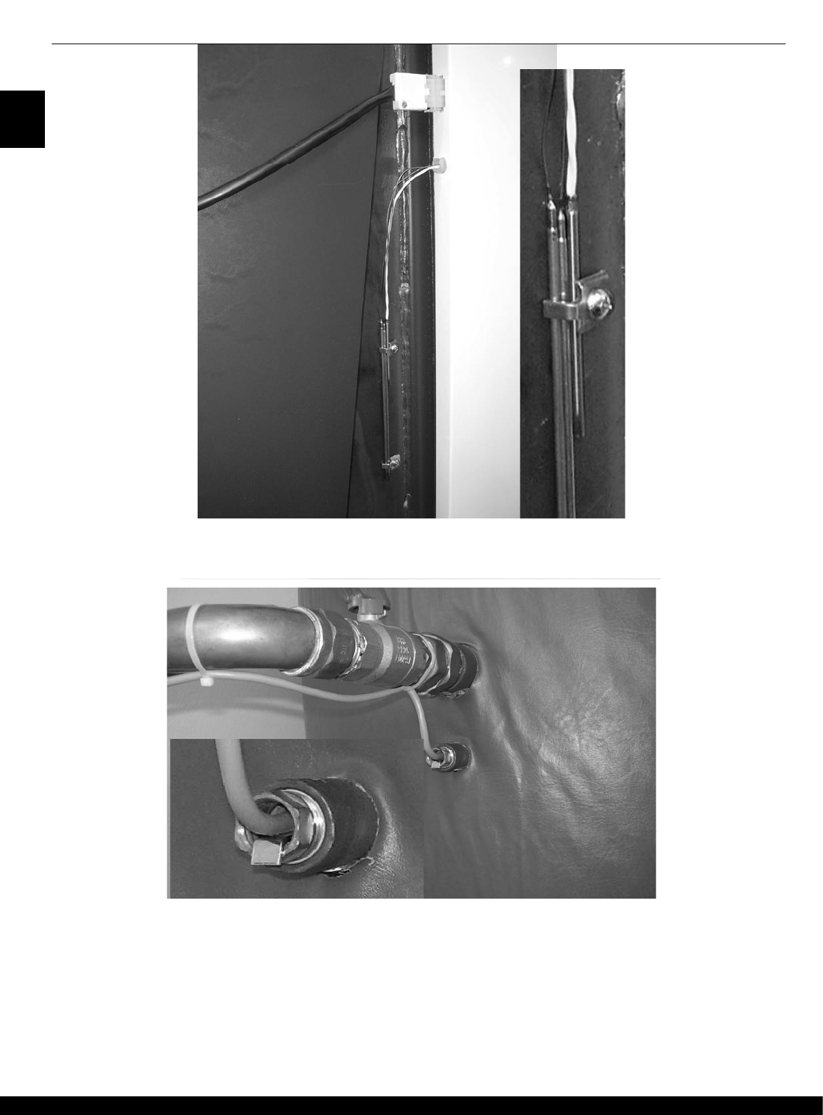
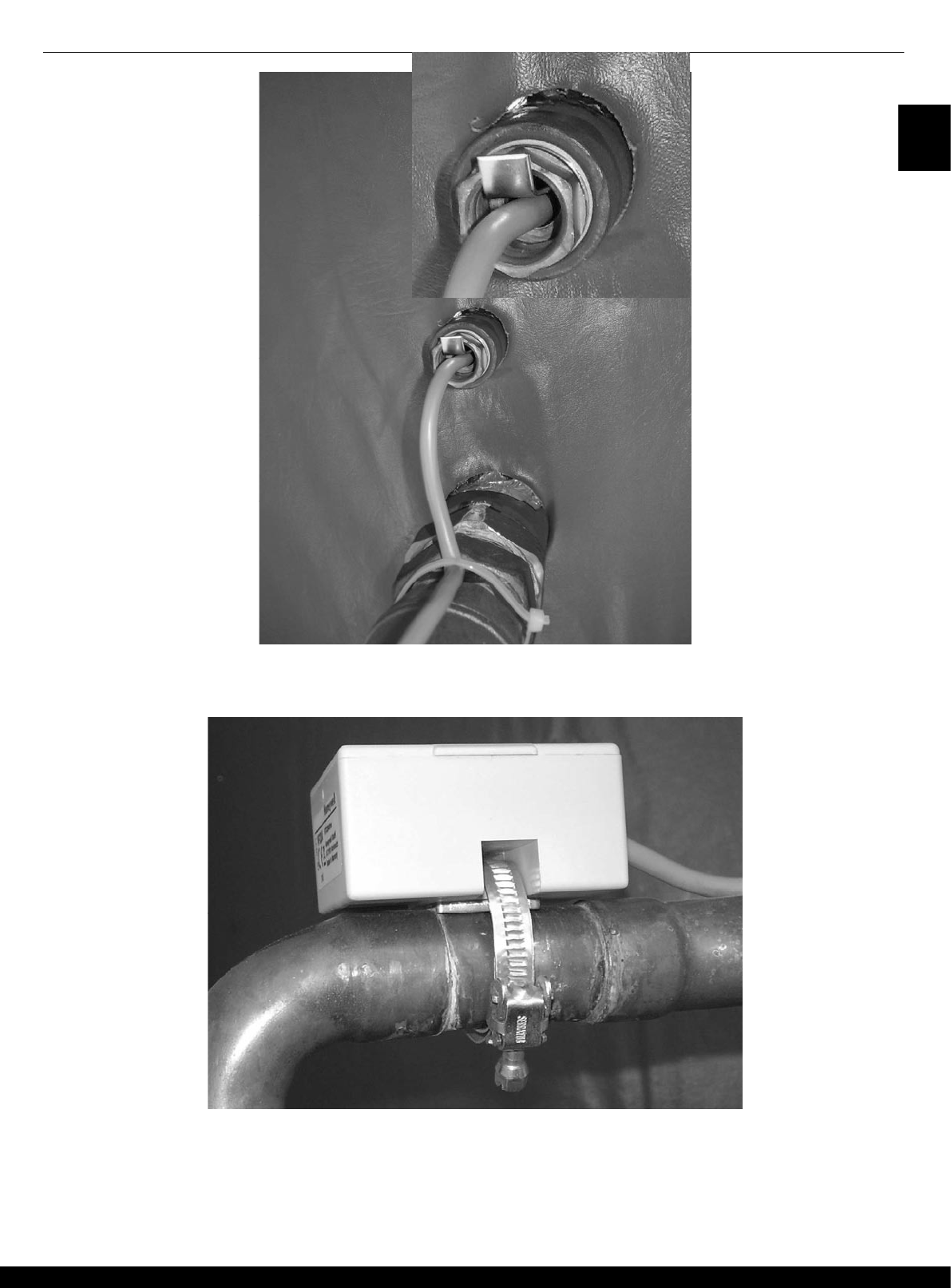
7.2.2.3 Safety regulations for electromagnetic compatibility (EMC).......................................................... 119
7.2.3 Minimum cable cross-sections.............................................................................................................. 122
7.2.4 Maximum cable length .......................................................................................................................... 122
7.2.5 Cable installation................................................................................................................................... 122
7.2.6 Grounding in switching boxes............................................................................................................... 122


 


 


 
 

 
7.6.1 Interconnection diagram of the SCS12 terminal board......................................................................... 123
7.6.2 Description of interconnection of the SCS12 terminal board................................................................ 124
7.6.3 Controller installation into the panel...................................................................................................... 125




 
7.7.1 Controller installation into the SWS12 terminal board .......................................................................... 127
 
 





8.1.1 Hydraulic example no. 1 – Non-controlled boiler connected without an accumulation tank ................ 129
8.1.2 Example of parameter settings for hydraulic diagram no. 001 ............................................................. 130



  
8.2.1 Hydraulic example no. 003 – Non-controlled boiler connected to an accumulation tank..................... 132
8.2.2 Example of parameter settings for hydraulic diagram no. 003 ............................................................. 133



  
8.3.1 Hydraulic example no. 4 – Non-controlled boiler connected with an accumulation tank and zone valve135
8.3.2 Example of parameter setting for hydraulic diagram no. 004 ............................................................... 136



  
8.4.1 Hydraulic example no. 009 – Pellet boiler connected without an accumulation tank........................... 138
8.4.2 Example of parameter settings for hydraulic diagram no. 009 ............................................................. 139



 
8.5.1 Hydraulic example no. 0010 – Pellet boiler connected with an accumulation tank .............................. 141
8.5.2 Example of parameters settings for hydraulic diagram no. 0010 ......................................................... 142



 
8.6.1 Hydraulic example no. 0012 – Pellet boiler connected with an accumulation tank and zone valve .... 144
8.6.2 Example of parameter settings for hydraulic diagram no. 12 ............................................................... 145



 
8.7.1 Hydraulic example no. 0017 – Boiler with a fan, flue gas sensor without an accumulation tank ......... 147
8.7.2 Example of parameter settings for hydraulic diagram no. 0017 ........................................................... 148



 
8.8.1 Hydraulic example no. 0019 – Boiler with a fan, flue gas sensor and accumulation tank.................... 150
8.8.2 Example of parameter settings for hydraulic diagram no. 0019 ........................................................... 151



 
8.9.1 Hydraulic example no. 0020 – Boiler with a fan, flue gas sensor, zone valve and accum. tank .......... 153
8.9.2 Example of parameter settings for hydraulic diagram no. 0020 ........................................................... 154



 
8.10.1 Hydr. diagram no. 0031 – combined boiler with a flue gas sensor, without an accumulation tank...... 156
8.10.2 Example of parameter settings for hydraulic diagram no. 0031 ........................................................... 157



 
8.11.1 Hydr. diagram 0032 – combined boiler with a flue gas sensor, with an accumulation tank ................. 159
8.11.2 Example of parameter settings for hydraulic diagram no. 0032 ........................................................... 160



 
8.12.1 Hydr. diagram no. 0033 – combined boiler with a flue gas sensor, accumulation tank and zone valve162
8.12.2 Example of parameter settings for hydraulic diagram no. 0033 ........................................................... 163


 
  
SDC12-31ACD01 CONTENTS
ATMOS ACD01 – SERVICE MANUAL EN
6
5.3.10.22 SOLID FUEL Menu / par. 21 – Operation of fan together with burner...........................................100
5.3.10.23 SOLID FUEL Menu / par. 22 – Summer heating of DHW by a boiler of type 5,6 ..........................101
5.3.11 SOURCES Menu...................................................................................................................................101
5.3.11.1 SOURCES Menu - overview of parameters...................................................................................101
5.3.11.2 SOURCES Menu / par. 1 – Automatic switch-over after burning out of SRC-1 ............................10
1
5.3.11.3 SOURCES Menu / par. 2 – Auto return to SRC-1 .........................................................................101
5.3.11.4 SOURCES Menu / par. 3 – Simultaneous operation of 2 sources - cascade................................102
5.3.11.5 SOURCES Menu / par. 4 – Zero temperature of the external source KT2zero.............................10
2
5.3.11.6 SOURCES Menu / par. 5 – Minimum temperature of the external source KT2min.......................102
5.3.11.7 SOURCES Menu / par. 6 – External source differential ................................................................102
5.3.11.8 SOURCES Menu / par. 7 – Maximum temperature of the external source KT2max.....................102
5.3.11.9 SOURCES Menu / par. 8 – Summer heating of DHW with SRC-3................................................102
5.3.11.10 SOURCES Menu / par. 9 – Comfortable EHP operation...............................................................103
5.3.11.11 SOURCES Menu / par. 10 – Summer heating of DHW with EHP .................................................103
5.3.11.12 SOURCES Menu / par. 11 – Delayed switch-on of EHP ...............................................................103
5.3.11.13 SOURCES Menu – Naming of SRC-1 ...........................................................................................103
5.3.11.14 SOURCES Menu – Naming of SRC-2 ...........................................................................................103
5.3.12 BUFFER Menu ......................................................................................................................................104
5.3.12.1 BUFFER Menu - overview of parameters ......................................................................................104
5.3.12.2 BUFFER Menu / par. 1 – Minimum buffer temperature .................................................................104
5.3.12.3 BUFFER Menu / par. 2 – Maximum buffer temperature ................................................................104
5.3.12.4 BUFFER Menu / par. 3 – Increasing the SET-POINT of the source..............................................105
5.3.12.5 BUFFER Menu / par. 4 – Buffer switching differential ...................................................................105
5.3.12.6 BUFFER Menu / par. 5 – Forced buffer losses..............................................................................105
5.3.12.7 BUFFER Menu / par. 6 – Extended switch-on differential time .....................................................105
5.3.12.8 BUFFER Menu / par. 7 – Extended switch-off differential time .....................................................105
5.3.12.9 BUFFER Menu / par. 8 – Buffer charging protection .....................................................................106
5.3.12.10 BUFFER Menu / par. 9 – Buffer charging protection .....................................................................106
5.3.12.11 BUFFER Menu / par. 10 – Buffer tank operation mode.................................................................106
5.3.12.12 BUFFER Menu / par. 11 – Extended pump running time ..............................................................106
5.3.12.13 BUFFER Menu / par. 14 – Minimum tank SET-POINT in operation..............................................106
5.3.12.14 BUFFER Menu / par. 15 – Protection switch-off differential during charging ................................107
5.3.12.15 BUFFER Menu / par. 16 – Protection switch-on differential during charging ................................108
5.3.13 DATA BUS Menu...................................................................................................................................109
5.3.13.1 DATA BUS Menu - overview of parameters ..................................................................................109
5.3.13.2 DATA BUS Menu / par. 1 – Controller bus address.......................................................................109
5.3.13.3 DATA BUS Menu / par. 2 – Access level of the SDW20 unit of the direct circuit ..........................109
5.3.13.4 DATA BUS Menu / par. 3 – Access level of the SDW20 unit - MC1..............................................109
5.3.13.5 DATA BUS Menu / par. 4 – Access level of the SDW20 unit - MC 2.............................................109
5.3.14 RELAY TEST Menu ..............................................................................................................................109
5.3.14.1 RELAY TEST Menu - overview of parameters ..............................................................................109
5.3.15 ALARMS Menu......................................................................................................................................110
5.3.15.1 List of ALARMS ..............................................................................................................................111
5.3.16 CALIBRATION Menu ............................................................................................................................112
5.3.16.1 CALIBRATION Menu - overview of parameters ............................................................................112
5.3.17 Bus communication ...............................................................................................................................113
5.3.17.1 BUS address of the control unit .....................................................................................................113
5.3.17.2 Control functions via BUS ..............................................................................................................113
5.3.17.2.1 Boiler control................................................................................................................................................ 113
5.3.17.2.2 Boiler corrosion temperature ....................................................................................................................... 113
5.3.17.2.3 Indirect return temperature control............................................................................................................... 113
5.3.17.2.4 DHW priority ................................................................................................................................................ 113
5.3.17.2.5 Heating requirement .................................................................................................................................... 11
3
5.3.17.2.6 Clock synchronization.................................................................................................................................. 11
4
5.3.17.2.7 Information about the room temperature ..................................................................................................... 114
5.3.17.2.8 Error / status indication................................................................................................................................ 114
5.3.17.3 Connection examples with multiple control units ...........................................................................114
Setting another controller connected to the BUS.............................................................................................................. 115
  













  
GB
www.atmos.cz
SDC12-31ACD01 CONTENTS
ATMOS ACD01 – SERVICE MANUAL EN
8
   
   









   



12.1.1 Installation recommendations................................................................................................................172









GB
www.atmos.cz
9-GB
OBSAH SDC12-31ACD01
9
ATMOS ACD01 – SERVICE MANUAL EN
1 Document Revision
This Service Manual was updated on February 1, 2011.
2 Software Version
This Service Manual can only be used in conjunction with software version V3.3. The
software version that is installed in your controller will be displayed for approx. 8
seconds after connection of the controller to the power supply.
3 Basic description
The ACD01 equithermal controller is programmed to control the boiler and system circuit
in accordance with specific hydraulic diagrams. For proper functioning the controller must
be set to the particular hydraulic diagram after the initial start-up; otherwise the controller
cannot control the heating system properly. This Service Manual provides instructions for
proper installation and setting of the controller.
The function of the controller consists in the calculation of SET-POINTS to cover the
needs of the heating system and their gradual shifting and increasing towards the boiler -
see diagram.






























GB
www.atmos.cz
GB-10
GB
www.atmos.cz
11-GB
SDC12-31ACD01
11
ATMOS ACD01 – SERVICE MANUAL EN
4.1 Basic displays of the controller
The display modes depend on the selected boiler type or hydraulic diagram.
Display 1 - hydraulic diagrams 1, 3, 4, 9, 10, 12 (boiler type 1, 2 and 3)
The display shows the date, time and temperature of the heat source (boiler)
Display 2 – hydraulic diagram 17, 19, 20 (boiler type 4)
The display shows fan operation, fan ventilation period, fan status, the time and
the temperature of the heat source (boiler).
Display 3 – combined source - type no. 5 and 6
The display shows the selected source, fan ventilation period and fan status
(SRC-1 only), temperature of the source.
The parasol symbol

indicates the summer mode of the controller.
The snowflake symbol

indicates active anti-freeze protection.





Active operation mode
Date
Symbols of operation modes
Boiler temperature
Time
<< 



Operation mode indicator
Fan operation and ventilation period
Symbols of operation modes
Boiler temperature
Time
Fan status
<< 





Active operation mode
Selected source or ventilation
period (SRC-1 only)
Symbols of operation modes
Boiler temperature
Time or accumulation tank
temperature (EHP only)
Status (SRC-1 only) or SRC-2
manually off
GB
www.atmos.cz
GB-12
SDC12-31ACD01
ATMOS ACD01 – SERVICE MANUAL EN
12
4.2 Control keys
4.2.1 Rotary button (Press / Turn)
By pressing the rotary button once, you can:
Confirm inputs/values
Enter individual parameters
Change the selection level in the menu
By prolonged pressing (approx. 3 sec.) of the rotary button, you can:
Enter the menu
By turning the rotary button, you can:
Change values (increase clockwise and decrease counter-clockwise)
Browse in the menu/parameters
4.2.2 “Daytime room temperature” key
This key is used to set the room temperature in the automatic mode during the
heating cycle as well as in the PARTY a HEATING operation modes. If in the
SYSTEM menu value 1 of the MODE parameter is selected, the entered value is
identical for all the heating circuits. If in the SYSTEM menu the MODE parameter is
set to 2, you can enter values for each of the heating circuits individually.
NOTE The value entered this way is the starting point for individual temperature settings
during heating cycles in the time program menu. If this value differs from the set
value, it is modified as necessary in case of a subsequent temperature change.
Setting:
Press the ”Daytime room temperature” key .
Set the required room temperature value by turning the rotary button to the
required value.
Confirm the set value either by pressing the “Daytime room temperature” key
or by pressing the rotary button
.
Default setting 20 °C
Setting range 5 ... 30 °C
4.2.2.1 Function of quick switching to the “PARTY” mode
By keeping the “DAYTIME TEMP.” key pressed for more than 3 sec. you will
switch the controller to the PARTY mode - see the operation modes 4.2.5.3.
4.2.3 “Night-time room temperature” key
This key is used to set the reduced temperature value in the automatic program
between heating cycles as well as during the ABSENCE and REDUCED operation
modes. If in the SYSTEM menu value 1 of the MODE parameter is selected, the
entered value is identical for all the heating circuits. If in the SYSTEM menu the
MODE parameter is set to 2, you can enter values for each of the heating circuits
individually.
Setting:
Press the “Night-time room temperature” key .
 - 











GB
www.atmos.cz
13-GB
SDC12-31ACD01
13
ATMOS ACD01 – SERVICE MANUAL EN
Set the required reduced room temperature by turning the rotary button to the
required value.
Confirm the set value either by pressing the “Night-time room temperature” key
or by pressing the rotary button 
Default setting 16 °C
Setting range 5 ... 30 °C
4.2.3.1 Function of quick switching to the “ABSENCE” mode
By keeping the “NIGHT-TIME TEMP. key depressed for more than 3 sec. you will
switch the controller to the ABSENCE mode - see the operation modes 4.2.5.2.
4.2.4 “Daytime DHW temperature” key
This key is used to set the DHW temperature value in the daytime mode during the
DHW operation times in the automatic program as well as during the PARTY and
HEATING operation modes.
The value entered this way is also used for the domestic hot water only mode
(manual summer mode).
NOTE The value entered this way is the starting point for individual temperature settings
during DHW cycles in the time program menu. If this value differs from the default
setting, it is modified as necessary in case of a subsequent adjustment of the set
value.
Setting:
Press the “DHW temperature” key .
Set the DHW buffer temperature by turning the rotary button to the required
value.
Confirm the set value either by pressing the “DHW temperature” key or by
pressing the rotary button 
Default setting 50 °C
Setting range Economic hot water temperature ... maximum temperature of the source of heat
(service setting)
4.2.4.1 One-off filling function in the daytime mode
By keeping the “DHW temperature” key pressed for more than 3 sec. you will
activate the function of one-off filling (heating) of hot water in the daytime mode. This
function suppresses the currently set time program.
After pressing of this button the time value will be displayed with the following
meaning:
0 s: The function of one-off filling will only be executed once until the DHW
temperature value is achieved. When the set value is reached, this
function will be switched off again.
>0 s: The hot water filling period will be executed for the time interval (0 to
240 minutes) set with the use of the rotary button. This means that the
filling function will be switched off after the expiration of the set time
interval independently of the subsequently set value.
















GB
www.atmos.cz
GB-14
SDC12-31ACD01
ATMOS ACD01 – SERVICE MANUAL EN
14
4.2.5 „Operation Mode“ key (Basic display)
This key is used to set the required operation mode. The operation mode appears in plain text and at
the same time the cursor at the bottom side of the display indicates the relevant operation mode
symbol. If in the SYSTEM menu the MODE parameter = 1, the set value is identical for all the heating
circuits; if in the SYSTEM menu the MODE parameter = 2 is selected, values are set separately for
each individual circuit.
Overview of the Operation Modes
Arrow
on symbol
Program Mode display Setting

Holiday
Day of return from holiday

Absence
Return time
Party
Party end time

Automatic
Time programs
1 (2, 3)
Summer
DHW temperature

Constant heating
mode
Comfortable temperature

Constant reduced
mode
Reduced temperature

Constant standby
mode



























 





 










GB
www.atmos.cz
15-GB
SDC12-31ACD01
15
ATMOS ACD01 – SERVICE MANUAL EN
Setting:
Press the “Operation Mode” key
Set the arrow at the bottom side of the display by turning to the position of the
desired operation mode.
Confirm the setting by pressing the “Operation Mode” key or the rotary
button
.
In the case of the short-term operation modes (Holiday, Absence, Party) set the
required value by turning the rotary button
and confirm the set value in the
above mentioned way.
Return to the basic display Keep the key
pressed for approx. 3 seconds.
4.2.5.1 Holiday Mode (Short-term Program)
By means of this mode you can switch off the heating and hot water heating for the
household for the whole holiday period. The frost protection remains activated.
Control in the Holiday Long absence during the heating season.
mode If outdoor temperatures are lower than the frost protection temperature, the heating
circuits without the SDW wall modules are controlled to the room temperature set
point of 3 °C and the circuits with SDW wall modules are controlled to their set frost
protection limit (see parameter 8 of the mixing circuit: room frost protection limit).
Setting See the “Operation Mode” key.
Terminating the Holiday
mode The activated "Holiday“ mode may be terminated at an early return. Simply press the
“Operation Mode” key and select the automatic mode.
Default setting Current date
Setting range Current date ... Current date + 250 days
Display An activated “Holiday” program appears on the basic display with the indication of
the return date.
4.2.5.2 Absence Mode (Short-term Program)
By means of this mode you can temporarily switch off the heating for a short
absence period. During the absence period all the heating circuits are controlled in
accordance with the specified room temperature. After the expiration of the set time
period the heating circuits automatically return to the operation mode that was active
before setting of the "Absence” mode. The short-term programs as Party or Holiday
are skipped in this mode.
Application Short-term absence during the heating season
Setting See the “Operation Mode” key.
Terminating the Absence
Mode The activated "Absence“ mode may be terminated at an early return. Simply press
the “Operation Mode” key and select the automatic mode.
Setting range 0,5 hours ... 24 hours, P1 (P2, P3)
Display An activated “Absence” program appears on the basic display with the indication of
the return time.










GB
www.atmos.cz
GB-16
SDC12-31ACD01
ATMOS ACD01 – SERVICE MANUAL EN
16
4.2.5.3 Party Mode (Short-term Program)
This program offers one-off immediate heating of all the heating circuits until a preset
time and completely or partly skips a coming or an already active reduced cycle.
After the expiration of the preset time period the heating circuits automatically return
to the operation mode that was active before setting of the Party mode. The short-
term programs as Absence or Holiday are skipped in this mode.
Application One-off unscheduled extension of the heating period or immediate start of heating
during the reduced mode.
Setting See the “Operation Mode” key
Terminating the Party mode The activated "Party“ mode may be terminated earlier as necessary. Simply press
the “Operation Mode” key and select the automatic mode.
Setting range 0,5 hours ... 24 hours, P1 (P2, P3)
Display An activated Party program appears on the basic display with the indication of the
duration of the party.
4.2.5.4 Automatic Mode
In the automatic mode automatic time programs with variable heating times are
available. Standard default time programs can be overwritten as necessary with your
own settings of switching times.
As necessary you can use up to three different switching programs.
All the three automatic programs contain for each weekday up to three heating
cycles per circuit with their own switch-on time, switch-off time and cycle
temperature.
NOTE Automatic programs P2 or P3 may only be selected if they have been enabled in the
System menu (Parameter 2 Time Program = P1-P3). If they are not enabled,
program P1 is active only.
Setting See the “Operation Mode” key.
Enabling programs P2 - P3 (extension for three weekly time programs)
System menu . Time Program = P1-P3
Display The active automatic program appears in the basic display with the current time and
date. If automatic programs P2 and P3 have been enabled, depending on the
selected program the corresponding symbol , 
, or is inserted.
Disable/enable P2-P3 Disabling programs P2 – P3 (only one weekly time program is active)
System menu - Time Program = P1
4.2.5.4.1 Extension for three weekly time programs P1-3
See the System - Time Menu Program = P1-P3
Display The active automatic program appears in the basic display with the current
time and date. If the P2 and P3 automatic programs have been enabled the

































GB
www.atmos.cz
17-GB
SDC12-31ACD01
17
ATMOS ACD01 – SERVICE MANUAL EN
corresponding symbol , , or is inserted. After the extension you can
program 3 cycles separated that can be switched e.g. in a transitional period or for
shift work. etc.
Disable/enable P2-P3 See the System - Time Menu.. Program = P1
4.2.5.5 Manual Summer Mode (DHW heating only)
In this program just the DHW heating circuit remains active and the temperature is
controlled on the basis of the set temperature value for hot water and the DHW
heating program. The heating system has frost protection.
NOTE The manual Summer mode can only be selected in control mode 1 as it influences
the overall function of the controller (heating + DHW).
Setting See the “Operation Mode” key.
Terminating the manual The active manual Summer mode may be terminated at an early return. Simply
Summer mode press the “Operation Mode” key and select the automatic mode.
Disable/Enable P2-P3 Disabling programs P2 – P3 (only one weekly time program is active)
System menu - Time Program = P1
The selected automatic program is activated by pressing of the rotary button. All the
heating circuits and the DHW circuit exclusively work in accordance with the
standard or adapted programmed switching times in automatic program P1.
The P1 program does not appear on the display.
Enabling programs P2 - P3 (extension for three weekly time programs)
System menu - Time Program = P1-P3
If the automatic program has been confirmed by pressing of the rotary button, the P1
program will start flashing. You can select the P2 … P3 programs by means of the
rotary button.
Display A manual “Summer” program appears on the basic display with the SUMMER
indication, the current time and date. If automatic programs P2 and P3 have been
enabled, the corresponding symbol , 
, or also appears depending on the
selected program. It corresponds to the valid program for DHW heating.
4.2.5.6 Constant Heating Mode
This program offers uninterrupted heating according to the set daytime temperature
in the room. DHW heating works continuously on the basis of the value set for DHW
heating.
Setting See the “Operation Mode” key.
Terminating the Constant The active Constant Heating Mode may be terminated any time. Simply press the
Heating Mode “Operation Mode” key and select the automatic mode.
NOTE The Constant Heating mode remains active until another mode is selected.
Display An active Constant Heating program appears on the display with the HEATING
indication.


























GB
www.atmos.cz
GB-18
SDC12-31ACD01
ATMOS ACD01 – SERVICE MANUAL EN
18
4.2.5.7 Constant Reduced Mode
This mode provides constant reduced heating according to the set reduced
temperature in the room within the corresponding ECO (frost protection off mode) or
RED (reduced mode) mode set in the heating circuit in compliance with the low limit
of the corresponding heating circuit.
See the options of the menu Unmixed Circuit, Mixing Circuit 1 or Mixing Circuit 2)
Parameter 1 = ECO. DHW heating works continuously according to the set reduced
temperature for hot water heating (see the DHW menu / Parameter 1- Reduced
DHW temperature).
NOTE The operation reduction remains active until another mode is selected.
Setting See the “Operation Mode” key.
Terminating the Constant The active Constant Heating Mode may be terminated any time. Simply press the
Reduced Mode “Operation Mode” key and select the automatic mode.
Display An active Reduced program appears on the display with the RED. HEATING
indication.
4.2.5.8 Standby Mode
In this mode the whole system is off and only the frost protection is active (all the
functions of the frost protection are active). DHW heating is off and just the frost
protection is active. At tank temperatures below 5°C water is heated to 8°C.
Application Complete switch-off of heating and DHW heating with complete frost protection.
Setting See the “Operation Mode” key.
Terminating the The active Standby mode may be terminated any time. Simply press the
Standby Mode “Operation mode” key and set the automatic mode.
NOTE Heating and heating of hot water are activated by an external demand or demand of
the other heating circuit connected via the bus. Pumps of the heating system are
activated for a short time every day (protection from pump blocking).
Display An active Standby program appears on the display with the STANDBY indication.
4.2.6 General RESET – in the basic display
If necessary, the controller can be reset in the basic display by simultaneous pressing of the
, ,
a
keys
> 3
sec. (until the controller is started again. This reset affects all the parameters of all the menus on the corresponding access
level.
NOTE! The reset will set all the parameters to the default value depending on the access level.











GB
www.atmos.cz
19-GB
SDC12-31ACD01
19
ATMOS ACD01 – SERVICE MANUAL EN
4.2.7 “Heating Curve” key
This key allows you to set the heating characteristics for the heating circuits in the
system by setting the heating curve on the basis of the character of the building
(rough setting). Setting the shape of the curve:
The inclination of the heating characteristic describes the relationship between a
change of the system temperature and a change of the outdoor temperature. In the
case of large heating surfaces, e.g. a floor heating system the heating curve is less
steep as compared to small heating surfaces (e.g. heating elements). The set value
is related to the lowest outdoor temperature on the basis of the heat demand
calculation.
NOTE As the curve defines the flow temperature into the system on the basis of the
outdoor temperature, which continuously changes during the heating period,
the curve is not likely to be set precisely correctly at the first try, i.e. the value
of the curve must be additionally adapted. The value of the curve should be
adapted after longer time periods and by small values and the development of
temperatures should be exactly observed.
Setting:
Press the “Heating curve” key .
By turning the rotary button select the required heating circuits (if there are
more than one).
Confirm your selection by pressing the rotary button.
Change the flashing value and confirm it by pressing the button.
To return to the basic display press the “Heating curve" key .
Setting range 0,20 ... 3,5
Default settings Mixing heating circuit 1 (MC-1): = 1.00
Mixing heating circuit 2 (MC-2): = 1.00






Outdoor temperature (
0
C)
Boiler flow temperature (
0
C)
T
room
(
0
C)
GB
www.atmos.cz
GB-20
SDC12-31ACD01
ATMOS ACD01 – SERVICE MANUAL EN
20
4.2.8 “System Information” key
Press the “Information” key and turn the rotary button to find out all information about the system - the current and calculated
values of individual sensors, statuses of controlled components and control modes of individual controlled heating circuits.
This key allows you to return from a certain menu level by one order back.
NOTE The information displayed depends on the installed components and control cycles.
Manual exit from the display: You can return to the basic display any time by pressing the
or

key.
Automatic exit from the display: The controller will automatically return to the basic display after expiration of
the set return time.
Turn the rotary button to display values - navigate in the information.
- The left value (small numerals) on the display indicates the required or calculated value – SET-POINT (by pressing
)
- The right value (large numerals) on the display indicates the current value.
Information
Display
Display condition
Remarks
Outdoor temp. (1)




Outdoor sensor connected Mean temperature / current temperature
Outdoor temp. (1)







Outdoor sensor connected
No error indication
Min./max. for the last 24 hours
Setpoints
(requirements)






INSTALLER level
There is a requirement either for the boiler (the
automatic boilers switched on) or for the accumulation
tank (hydraulic diagram with an accum. tank) from DHW
and from MIXES
Boiler temp.





WF/KF sensor connected Set value / current value
Tank temperature,
bottom





Bottom sensor of the accumulation
tank
If boiler type 3, 5, 6 or e.g. solar is defined
External blocking of
boiler burner





External contact connected to VI-1,
VI-2 or VI-3
Only boiler with a burner and if the corresponding
parameter is set.
Flue gas temp.




Var. input set as AGF – boiler type
no. 4, 5 or 6 only
Connection only to the Variable input in VI-1
DHW temp.




DHW sensor connected Required value / current value
DHW-2 temp.




DHW-2 sensor connected Required value / current value
Heat demand via switch
contact (VI-1)




VI 1 set ON/OFF
Heat demand via switch
contact (VI-2




VI 2 set ON/OFF
Heat demand via switch
contact (VI-3)




VI 3 set ON/OFF
Water temp
VF1 (MIX1)





If mixing circuit 1 is used Calculated value / current value
Water temp.
VF2 (MIX2)





If mixing circuit 2 is used Calculated value / current value
Room temp
MIX1





If room temp. sensor is connected
and released for MIX1
Calculated value / current value
Room temp.
MIX2





If room temp. sensor is connected
and released for MIX2
Calculated value / current value
GB
www.atmos.cz
21-GB
SDC12-31ACD01
21
ATMOS ACD01 – SERVICE MANUAL EN
Information
Display
Display condition
Remarks
Thermostatic function
MIX1




If there is the thermostatic function of
the corresponding mixed circuit
ON/OFF
Thermostatic function
MIX2




If there is the thermostatic function of
the corresponding mixed circuit
ON/OFF
Tank temperature, top




PF sensor connected Calculated value / current value
Info temperature




Sensor connected and VI configured
Independent info temperature connected to the variable
input VI-1, VI-2 or VI-3
Operation mode
External switching
modem




VI configured as an external
switching modem
Operation modes depending on the setting of the
modem: AUTO (automatic) STBY (standby), HEAT
(heating), RED (reduced).
Solar collector
temperature




VO1/2 set as the solar panel pump Current temperature of the solar collector
Solar buffer
temperature




VO1/2 set as the solar panel pump
Current temperature of the buffer (accumulation tank)
charged by the solar system
Solar buffer 2
temperature




VO1/2 set as the pump of the solar
panel and solar switch
Current temperature of the buffer 2 charged by the solar
system
Heat output of solar
heating



VO1/2 set as the solar panel pump
and a sensor of return temperature
of the solar circuit is used
Current gain of the solar system in kW
Solar heating gain



VO1/2 set as the solar panel pump
and a sensor of return temperature
of the solar circuit is used
Total heat capacity of the solar system in kWh
Number of starts of the
solar panel pump



VO1/2 set as the solar panel pump
Information about the number of starts of the charging
pump of the solar system
Operation hours of the
solar panel pump




VO1/2 set as the solar panel pump
Information about the number of starts of the charging
pump of the solar system
Operation hours of the
boiler pump


Information about the operation hours of the solid fuel
boiler –with regard to the number of starts the lengths of
heating cycles of the boiler can be estimated.
Number of starts of the
boiler pump


Information about the number of starts of the boiler
pump
Function and status of
the optional output 1


Defined variable output VA1 Information about the status of VA1 (ZKP, ELH, etc.)
Function and status of
the optional output 2


Defined variable output VA2 Information about the status of VA2 (ZKP, ELH, etc.)
Operation status of the
boiler pump


ON/OFF
Operation status of the
GSE boiler servo flap



Boiler no. 4 only OPENING / CLOSING
Operation status of the
controlled boiler




Controlled boiler only ON / OFF
Operation status of
DHW



If a DHW sensor is connected
AUTO – operation mode
DAY – day/night demand
DHW – corresponding circuit
ON - status of the SLP pump
Operation status of the
MIX2 servo drive



If mixing circuit 2 is connected Mixing valve 2 opens / closes or is at standstill
GB
www.atmos.cz
GB-22
SDC12-31ACD01
ATMOS ACD01 – SERVICE MANUAL EN
22
Information
Display
Display condition
Remarks
Operation status of
mixing circuit 2



If mixing circuit 2 is connected
AUTO – operation mode
DEN – Day/night demand
MIX-2 – corresponding circuit
ON - status of the MCP2 pump
Operation status of the
MIX1 servo drive



If mixing circuit 1 is connected Mixing valve 1 opens / closes or is at standstill
Operation status of
mixing circuit 1



If mixing circuit 1 is connected 1
AUTO – selected operation mode
DAY – day / ECO - reduced temperature
MIX-1 – corresponding circuit
ON - status of the MKP1 pump
Date and current time


Day, date, year, time
4.2.8.1 Setting the time for automatic return
If the “Information” key is pressed for more than 3 sec.,
the INFO TIME parameter appears.
This parameter determines the time for automatic return to the basic display.
Setting range OFF, 1 ... 60 min
OFF The last displayed information remains on the
display.
1 ... 60 min Automatic exit from the information level
after the specified time, adjustable with the step of 0.5 min
Default setting OFF





GB
www.atmos.cz
23-GB
SDC12-31ACD01
23
ATMOS ACD01 – SERVICE MANUAL EN
4.2.9 Fan / Source selection key
The “Fan mode - Ventilation period” key is used to control the boiler fan if the boiler
type 4, 5 or 6 has been defined (in the case of the combined types 5 and 6 it is only
valid for SOURCE-1)
The fan controls the operation of the boiler with regard to the water and flue gas
temperature. The way of control differs depending on the fan type (pressure or
exhaust), i.e. the exhaust fan is left on during the opening of the boiler door while the
pressure fan must be switched off by pressing of the key before the opening of the
door. The fan type, switch-off temperature, differential, etc. is set by the INSTALLER
within the definition of parameters; the default fan type is exhaust.
In the case of an exhaust fan manual operation is only used during the start-up or
cleaning of the boiler; during normal boiler operation the fan is switched off when
the operation temperature is achieved, i.e. its operation is completely automatic and
is controlled by the controller. If it is necessary to start the fan in case the operation
temperature has been achieved, by pressing the key you will activate the ventilation
period, which is indicated on the display by counting down of the configured period
to 00:00; if the boiler achieves the critical temperature, the fan will be switched off in
a forced way.
The operation of a pressure fan only differs from the exhaust one in that it must be
switched off before the opening of the door (by pressing the key). Again, the display
will show the count-down of the ventilation period and after its expiration the display
will return to the normal automatic mode.
During the start-up of the boiler, i.e. when the flue gas temperature is below the
minimum value, after the expiration of the ventilation period a 60-minut switched-on
fan period is automatically activated to support burning up of the boiler.
Priorities for the fan running time:
Priority 1: Safety function - the fan is always switched off at the critical
temperature of the boiler
Priority 2: Manual fan control - during the start-up, operation or cleaning of the
boiler
Priority 3: Automatic mode - during boiler operation
4.2.9.1 Function 1 - boiler fan control (boiler type 4, 5 and 6)
Boiler out

[TWO arrows flash on the display]
Waiting for pressing of the key
The flue gas temperature is below the minimum value (boiler out)
Boiler start press the key.
……
[TWO arrows on the display are
permanently displayed]
Count-down of the ventilation period Ta
Press the key to stop the timer and the fan.
Normal boiler operation … (if necessary, press the key to switch off the pressure fan).

[ONE arrow - Tb= 60min for burning up, active after the
start,
TWO arrows = normal operation]
Waiting for pressing of the key
The flue gas temperature is above the minimum value (boiler on)
Note: If you inadvertently press the key, you may reactivate the operation of the fan by
pressing the key once again.
GB
www.atmos.cz
GB-24
SDC12-31ACD01
ATMOS ACD01 – SERVICE MANUAL EN
24
4.2.10 Function 2 – manual switching of SRC-1 and SRC-2 sources (boiler type 5 and 6
only)
By keeping the
key pressed for more than 3 seconds you will activate the menu for SOURCE selection in accordance
with the pre-defined boiler type 5 or 6. Turn the
button to select between the SRC-1 and SRC-2 sources (you can assign
your own names to the sources in the SOURCES menu). Press

to confirm your selection by YES/NO (protection from
wrong selection).
4.2.10.1 Indications on the display
When the key is kept pressed for
>
3 sec., the source selection, i.e. the boiler
type selection menu will appear. Select the source by turning
and confirm your
selection by pressing
.
Boiler type no. 5 – you can make your selection between SRC-1 (controlled solid fuel boiler
no. 4) and SRC-2 (controlled automatic boiler without an accumulation tank -
type no. 2).
Boiler type no. 6 – you can make your selection between SRC-1 (controlled solid fuel boiler
no. 4) and SRC-2 (controlled automatic boiler with an accumulation tank -
type no. 3).
Switching between the SRC-1 and SRC-2 sources is subject to the current status of the boiler, i.e. whether it is on or not, which
is monitored through the flue gas temperature (AGF), i.e. you can only switch over to the selected source after burning out (drop
below AGFmin). If the flue gas temperature is still high, the boiler type is indicated by the flashing text of the selected source.
After switching over to the selected source the display will correspond to the particular boiler type.
4.2.10.2 Manual stopping of the automatic heat source (SRC-2)
When the automatic source (SRC-2) is selected, after short pressing of the selection
of release (ON) or prohibition (OFF) of its operation will be displayed. You can make your
selection by turning
and confirm it by pressing
.
4.2.11 Example of navigation in the menu





short pressing
(CLICK)






(CLICK)










 
replenishing fuel at the fan off normal operation boiler out





pressing >3sec


SELECT
(turn)


CONFIRM
(CLICK)


SELECT
turn)


CONFIRM
(CLICK)








short pressing

SELECT
(turn)

CONFIRM
(CLICK)










GB
www.atmos.cz
25-GB
SDC12-31ACD01
25
ATMOS ACD01 – SERVICE MANUAL EN
5 Controller Parameters Menu
The ATMOS ACD01 equithermal controller features menus that contain values of parameters for setting and
functions of the controller. The parameters are defined in different units or expressions belonging to specific
functions. As protection from wrong setting some parameters or menus are hidden and are only displayed for
the higher access level.
5.1 Entering the menu
To enter the menu you must keep the rotary button

pressed for > 3 s.
The first parameter menu that is displayed is the menu of time programs;
you can select all the other menus by turning the

button
To enter the required menu, to enter parameter editing and to confirm the parameter
value press the

rotary button.
To move in the opposite direction, i.e. one level back, press the info

key.
Similarly, in case of inadvertent entering of a parameter or an incorrect value
after pressing of the
info

key the parameter value will remain in the original
condition.
The current position in the menu is indicated by flashing, i.e. if the menu name
flashes = the current position is menu selection, if the parameter number flashes =
the current position is parameter selection, if the parameter value flashes, the current
position is editing the parameter value.
You can return from the menu to the basic display by pressing the

key.
5.1.1 Example of navigation in the menu
BASIC DISPLAY
press > 3 s






turn
KLIK







turn
CLICK







turn
CLICK


 
CLICK

5.2 Entering the coded menu access level (TECHNICIAN/OEM)
By entering the access code you will unlock parameters or information of the
corresponding level.
Code input: Simultaneously press the
and

keys for more than 3 sec. to display the
request for the four-digit code.


Use the rotary button to gradually set the digits from the first to the last flashing digit
to the required value (the first digit will start flashing first, then, after confirmation the
second digit will flash, etc.)
GB
www.atmos.cz
GB-26
SDC12-31ACD01 Ovládání
ATMOS ACD01 – SERVICE MANUAL EN
26
5.3 Overview of menus of the ACD01 controller
   































































































































































































































































































































































































SDC12-31ACD01
ATMOS ACD01 – SERVICE MANUAL EN
24
4.2.10 Function 2 – manual switching of SRC-1 and SRC-2 sources (boiler type 5 and 6
only)
By keeping the
key pressed for more than 3 seconds you will activate the menu for SOURCE selection in accordance
with the pre-defined boiler type 5 or 6. Turn the
button to select between the SRC-1 and SRC-2 sources (you can assign
your own names to the sources in the SOURCES menu). Press

to confirm your selection by YES/NO (protection from
wrong selection).
4.2.10.1 Indications on the display
When the key is kept pressed for
>
3 sec., the source selection, i.e. the boiler
type selection menu will appear. Select the source by turning
and confirm your
selection by pressing
.
Boiler type no. 5 – you can make your selection between SRC-1 (controlled solid fuel boiler
no. 4) and SRC-2 (controlled automatic boiler without an accumulation tank -
type no. 2).
Boiler type no. 6 – you can make your selection between SRC-1 (controlled solid fuel boiler
no. 4) and SRC-2 (controlled automatic boiler with an accumulation tank -
type no. 3).
Switching between the SRC-1 and SRC-2 sources is subject to the current status of the boiler, i.e. whether it is on or not, which
is monitored through the flue gas temperature (AGF), i.e. you can only switch over to the selected source after burning out (drop
below AGFmin). If the flue gas temperature is still high, the boiler type is indicated by the flashing text of the selected source.
After switching over to the selected source the display will correspond to the particular boiler type.
4.2.10.2 Manual stopping of the automatic heat source (SRC-2)
When the automatic source (SRC-2) is selected, after short pressing of the selection
of release (ON) or prohibition (OFF) of its operation will be displayed. You can make your
selection by turning
and confirm it by pressing
.
4.2.11 Example of navigation in the menu





short pressing
(CLICK)






(CLICK)










 
replenishing fuel at the fan off normal operation boiler out





pressing >3sec


SELECT
(turn)


CONFIRM
(CLICK)


SELECT
turn)


CONFIRM
(CLICK)








short pressing

SELECT
(turn)

CONFIRM
(CLICK)










GB
www.atmos.cz
27-GB
SDC12-31ACD01
25
ATMOS ACD01 – SERVICE MANUAL EN
5 Controller Parameters Menu
The ATMOS ACD01 equithermal controller features menus that contain values of parameters for setting and
functions of the controller. The parameters are defined in different units or expressions belonging to specific
functions. As protection from wrong setting some parameters or menus are hidden and are only displayed for
the higher access level.
5.1 Entering the menu
To enter the menu you must keep the rotary button

pressed for > 3 s.
The first parameter menu that is displayed is the menu of time programs;
you can select all the other menus by turning the

button
To enter the required menu, to enter parameter editing and to confirm the parameter
value press the

rotary button.
To move in the opposite direction, i.e. one level back, press the info

key.
Similarly, in case of inadvertent entering of a parameter or an incorrect value
after pressing of the
info

key the parameter value will remain in the original
condition.
The current position in the menu is indicated by flashing, i.e. if the menu name
flashes = the current position is menu selection, if the parameter number flashes =
the current position is parameter selection, if the parameter value flashes, the current
position is editing the parameter value.
You can return from the menu to the basic display by pressing the

key.
5.1.1 Example of navigation in the menu
BASIC DISPLAY
press > 3 s






turn
KLIK







turn
CLICK







turn
CLICK


 
CLICK

5.2 Entering the coded menu access level (TECHNICIAN/OEM)
By entering the access code you will unlock parameters or information of the
corresponding level.
Code input: Simultaneously press the
and

keys for more than 3 sec. to display the
request for the four-digit code.


Use the rotary button to gradually set the digits from the first to the last flashing digit
to the required value (the first digit will start flashing first, then, after confirmation the
second digit will flash, etc.)
Ovládání SDC / DHC 43
27
ATMOS ACD01 – SERVICE MANUAL EN










































































SDC12-31ACD01 Ovládání
ATMOS ACD01 – SERVICE MANUAL EN
26
5.3 Overview of menus of the ACD01 controller
   































































































































































































































































































































































































GB
www.atmos.cz
GB-28
SDC12-31ACD01
ATMOS ACD01 – SERVICE MANUAL EN
28
5.3.1 DATE Menu
In the Date menu you can select the following parameters:
5.3.1.1 DATE Menu / par. 1 – Time
- Setting the current time
5.3.1.2 DATE Menu / par. 2 - Calendar year
- Setting the current year
5.3.1.3 DATE Menu / par. 3 - Day / Month
- Setting the current day in the month
5.3.1.4 DATE Menu / par. 4 - Time changeover mode
- Automatic switching between the summer / winter time
All the above mentioned values are pre-set in the factory and they do not need to be
changed. The internal pre-programmed calendar enables automatic changeover
from the summer to winter time and vice versa. This function can be deactivated if
necessary.
The current weekday from Mon to Sun is automatically derived from the calendar
date.
Change
Select the menu by pressing the rotary button
.
In the Date menu select the required parameter (time, year, day-month) by
turning the button
.
Press the rotary button
and change the value by turning the button
.
Confirm the value by pressing the rotary button
.
If desired, change and confirm the other calendar parameters as described
above by turning the button
.
Exit To exit the menu and return to the basic display press the “Operation Mode” key
.
5.3.2 TIME PROGRAMS Menu
In this menu you can set individual time programs for the heating and preparation of
hot water for the household. The standard default program P1 (as well as P2 and
P3 if they are enabled) for each heating circuit can be overwritten with your own
values of switching times and temperature values. This is particularly useful if you
need to create specific, periodically recurring personal heating programs (e.g. in
case of work in shifts, etc.).
For the programming of switching times max. 3 heating cycles (P1-P3) with their
own switch-on and switch-off times are available for each weekday . Each heating
cycle can also be combined with a freely selectable temperature value.
IMPORTANT!
If you overwrite standard programs with your own settings, the standard programs are not lost.
After reloading of the standard programs your personalized programs will be deleted.
Exit To exit the menu and return to the basic display press the “Operation Mode” key.
5.3.2.1 TIME PROGRAMS Menu / par. 1,2,3 – Selection of the MC 1,2 and DHW circuits
After entering the switching menu you can use the rotary button o select the desired
parameter - heating circuit - in the following order:
- Mixing heating circuit 1 (MC-1)
- Mixing heating circuit 2 (MC-2)
- Domestic hot water circuit (DHW)
You can access the selected circuit by pressing the rotary button.
GB
www.atmos.cz
29-GB
SDC12-31ACD01
29
ATMOS ACD01 – SERVICE MANUAL EN
5.3.2.1.1 Program Selection
If time programs P1 and P3 are enabled (see the System menu / Time Program = P1
P3); the program selection menu will appear.
If time switching programs P2 and P3 are not enabled (see the System menu /
Parameter 2 - Time Program = P1 P3), the program selection menu is automatically
skipped.
5.3.2.1.2 Weekday and cycle selection
After the selection of the program the first cycle of the first weekday (MO-1) will appear
and the corresponding section will start to flash in the upper time bar. You can select
other cycles by turning the button clockwise in the sequence of the cycles and weekdays
(e.g. Mo-1, Mo-2, Mo-3, Tue-1, Tue-2, Tue-3 while after setting these cycles should be
selected by turning of the button counter-clockwise and confirmed by pressing of the
rotary button.
5.3.2.1.3 Programming switching times and cycle temperatures
5.3.2.1.3.1 Switch-on time
Start of heating, or with enabled optimization: start of maintenance.
After the selection of the weekday and corresponding cycle the relevant switch-on time
will start flashing on the display and you can set it directly with the rotary button. The time
column in the upper part of the display provides an overview of all the programmed
cycles between 00:00 and 24:00 of the selected weekday.
IMPORTANT NOTE
-The switch-on time cannot be set earlier than the switch-off time of the previous cycle (if
it is set) and not earlier than 0:00 of the selected weekday.
- When you set a switch-on time, the corresponding time item in the column on the left
will change.
- If the switch-on time coincides with the switch-off time, the cycle will be deleted. The
deleted cycle will be replaced with the following cycle (if available).
- If you subsequently set an earlier cycle, the corresponding weekday will have to be
reprogrammed.
- You can display flashing switch-on time by pressing the rotary button.
5.3.2.1.3.2 Switch-off time
End of heating, or with enabled optimization: end of maintenance.
After setting of the switch-on time the corresponding switch-off time will start flashing on
the display and you will be able to set it directly with the rotary button. The time column in
the upper part of the display provides an overview of all the programmed cycles between
00:00 and 24:00 of the selected weekday.
IMPORTANT NOTE - You cannot set the switch-off time later than the switch-on time of the next cycle (if set).
- When you set a switch-off time, the corresponding time item in the column on the right
will change.
- If the switch-off time coincides with the switch-on time, the cycle will be deleted. The
deleted cycle will be replaced with the following cycle (if available).
- If you subsequently set an earlier cycle, the corresponding weekday will have to be
reprogrammed.
- You can display flashing switch-off time by pressing the rotary button.
5.3.2.1.3.3 Cycle temperature
After setting of the switch off time the corresponding cycle temperature will start flashing
on the display and you can set it directly with the rotary button. In the case of heating
circuits the displayed temperature always refers to the desired room temperature while in
the case of DHW heating it refers to the desired normal DHW temperature in the
selected cycle.
- You can display flashing cycle temperature by pressing the rotary button.
At the same time the last cycle to be called will start flashing on the display and it can be
checked. Then you can directly select further cycles in the following sequence: SWITCH-
ON TIME - SWITCH-OFF TIME - CYCLE TEMPERATURE.
GB
www.atmos.cz
GB-30
SDC12-31ACD01
ATMOS ACD01 – SERVICE MANUAL EN
30
5.3.2.1.3.4 Programming switching times (Programs P2 and P3 disabled)
After selection of the menu on the parameter level the time programming function will appear.
BASIC DISPLAY
Press for 3 s

MENU – SELECTION

Return:
press for 3 s..
TIME -
CALENDAR
TIME
PROGRAMS
System
parameters
MC1 etc.
Press


Return:
press for 3 s..
Heating circuit
Select
MC 1
MC 2 TUV STANDARD Copy circuits
Press


Return:
press for 3 s..
Day & cycle
Select
MON
Heating cycle 1
MON
Heating cycle 2
MON
Heating cycle 3
TUE
Heating cycle 1
WED.– THU. –
FRI – SAT
SUN
Last heating cycle
Copy days
Press


Return:
press for 3 s..
Switch-on time
Change

Start heating
Press


Return:
press for 3 s..
Switch-off time
Change

Stop heating
Return
Press


Return:
press for 3 s..
Temperature
Change
TEMPERATURE
SETTING
Press

Return to the basic display by pressing the

key.
Standard time program P1 Standard time program (P1) for heating and DHW
Heating circuit Day
Heating mode
from to
Automatic heating and DHW preparation function
for each weekday
DHW heating
circuit
Mo –
Su
5:00 – 22:00
Mixing circuit
1/2
Mo –
Su
6:00 – 22:00
If programs P1-P3 are enabled, the time program may be configured in accordance with the following tables.
Standard program P1
Standard program P2
Standard Program P3
Heating circuit Day
Heating
mode
from to
Heating
circuit
Day
Heating mode
from to
Heating circuit Day
Heating
mode
from to
DHW heating
circuit
Mo – Su 5:00 – 22:00
DHW heating
circuit
Mo – Th
Fr
Sa – Su
5:00-8:00 15:30-22:00
5:00-8:00 12:30-22:00
6:00-23:00
DHW heating
circuit
Mo – Fr
Sa – Su
6:00 – 18:00
reduced
Mixing circuit ½ Mo. – Su 6:00 – 22:00 Mixing circuit 1/2
Mo – Th
Fr
Sa – Su
6:00-8:00 16:00-22:00
6:00-8:00 13:00-22:00
7:00-23:00
Mixing circuit 1/2
Mo – Fr
Sa – Su
7:00 – 18:00
reduced
GB
www.atmos.cz
31-GB
SDC12-31ACD01
31
ATMOS ACD01 – SERVICE MANUAL EN
5.3.2.2 TIME PROGRAMS Menu / par. 4 - Reloading standard programs
Personalized time programs P1, P2 or P3 can be overwritten by standard time
switching programs P1, P2 or P3 if necessary.
After entering the menu of switching programs you must select the STANDARD
TIME function in the heating cycle.
After confirmation with the rotary button the circuit the setting of which should be
overwritten by a standard program (MC-1, MC-2, ALL) will start flashing on the
display.
If automatic programs P1, P2 and P3 are enabled (see the System menu - Time
Program = P1-3), you can select the desired switching program P1, P2 or P3 of the
circuit the setting of which should be overwritten by a standard program. If they are
not enabled, the program selection is skipped.
Reset Restoration of the original values occurs together with pressing of the rotary button
for approx. 5 seconds until the confirmation information appears on the display.
The reset is confirmed by the “COPY OK” message.
The STANDARD TIME function can be invoked as necessary if you need to replace
the settings of the other circuits with their corresponding standard programs.
NOTE If you select ALL, the settings of all the heating circuits and DHW circuits
assigned to the selected program will be overwritten by their standard
switching times.
After the overwriting all the personalized time programs are irreversibly lost
and they must be created again.
To return to the basic display press the program selection key
.
5.3.2.3 TIME PROGRAMS Menu / par. 5 - Copying Time Programs (Blocks)
5.3.2.3.1 Copying the Switching Time Programs (Days)
Block programming offers copying of switching times and cycle temperatures of the
selected weekday:
1 – Specific weekday (Mo, Tu, We, … Su)
2 – All the working days (Mo to Fr)
3 – Weekend (Sa to Su)
4 – All the week (Mo to Su)
5.3.2.3.1.1 Calling the Copy function (Days)
Source day After selection of the copy function you can select the source day that you want to
copy (Mo to Fr) by pressing the rotary button. The corresponding automatic program
P1 (P2, P3) of the source day will appear on the display together with the clock
symbol and program index.
Target day When you have confirmed the source day by pressing the rotary button, the target
day following after the source day will start flashing on the display. By means of the
rotary button you can select:
- individual following source days (Mo - Fr);
- all the days of the week (1-7) as a weekly block;
- all the working days (1-5) as a working day block;
- the weekend (6-7) as a weekend block;
and confirm by pressing the rotary button.
The copy function is accomplished by the confirming message ”COPY OK”.
After the confirmation once you press the rotary button, the next target days will
gradually appear on the display. You can select or skip these days as necessary.
You can return to the basic display by pressing the program selection key
.
NOTE Only complete days with the settings of cycles, temperatures and corresponding
programs can be copied.
GB
www.atmos.cz
GB-32
SDC12-31ACD01
ATMOS ACD01 – SERVICE MANUAL EN
32
5.3.2.3.2 Copying switching time programs (heating circuits)
- par.5 - Block copying allows you to copy switching times and temperature settings
from a heating cycle to another one.
5.3.2.3.2.1 Calling the Copy function (heating circuits)
Source circuit After selection of the copy function you can select the source mixing circuit that you
want to copy (MC-1, MC-2, WW) by pressing the rotary button.
If automatic programs P1, P2 and P3 are enabled (see the System menu -
Parameter - Time Program = P1-3), you can select the desired switching program
P1, P2 or P3 of the source circuit. If they are not enabled, the program selection is
skipped.
Target circuit After confirming the source circuit by pressing the rotary button you can select the
target circuit in the same way and confirm the required program if it is enabled.
The copy function is confirmed by the “COPY OK” message. The copy function can
be invoked again for copying other circuits if necessary.
IMPORTANT NOTE Heating circuits cannot be copied to hot water heating circuits and vice versa due to
different temperature settings. If a heating circuit (MC-1, MC-2) is set as the source
circuit, the hot water circuit (DHW) is excluded from the list of possible target
circuits.
A source hot water circuit may be a target and a source circuit at the same time. In
this case only switching programs P1 - P3 can be copied between each other.
You can return to the basic display by pressing the program selection key
.
GB
www.atmos.cz
33-GB
SDC12-31ACD01
33
ATMOS ACD01 – SERVICE MANUAL EN
5.3.3 HYDRAULIC Menu
The Hydraulic menu defines which components are connected to the controller.
5.3.3.1 HYDRAULIC Menu - overview of parameters
Par
.
Description
Setting range / Setting values
Default
setting
Setting
01
Hydraulic diagram 0001 - 0020 0019
02
DHW pump output OFF No function
1 SLP - DHW loading pump
4 ZKP - DHW circulation pump
5 ELH - DHW electric heating element
46 ETUV - Controlled electric heating of the DHW tank
1
03
Output of mixing circuit 1 (MC1) OFF No function
2 DK - Direct circuit (pump output only)
3 MK - Mixing circuit 1 (OTC)
6 KR -Mixing circuit 1 (as a constant controller)
7 FR - Mixing circuit 1 (as a fixed value controller)
8 RLA - Mixing circuit 1 (as a boiler return controller)
40 KRK - Mixing circuit 1 (constant cooling
temperature)
45 EHP - Electric heating of the accumulation tank
3
04
Output of mixing circuit 2 (MC2) Setting scope and assignment as parameter 03 3
05
Output of heating circuit pump (HC) Fixed settings KKPF KKPF
06
Variable output 1 (zone valve) - VO1 OFF No function
4 ZKP - DHW circulation pump
5 ELH - DHW electric heating element
9 RLP- Boiler pump
10 ZUP - Charging pump
11 KP1 -Pump of boiler circuit 1
12 KP2 -Pump of boiler circuit 2
13 SMA - General alarm output
15 SOP - Solar heating charging pump
16 PLP - Zone valve of the boiler circuit
19 SLV - Solar charging switch
20 SZW - Forced solar system losses
21 PWF - Parallel heating enabled
26 PP - Main pump
27 HPE - Hydraulic buffer support
41 UHK - Heating/cooling switch
45 EHP - Electric heating of the accumulation tank
46 ETUV - Controlled electric heating of the DHW tank
OFF
07
Variable output 2 - VO2 Setting scope and assignment as parameter 06 OFF
8
Variable input 1 – VI1 OFF No function
1 AF2 - Outdoor sensor 2
2 KF2 - Boiler sensor 2
3 SF2 - DHW tank sensor 2
4 PF2 - Tank buffer sensor 2
5 ANF- Switching contact
6 SME - External alarm input
7 RL1 - Return sensor for mixing circuit 1
8 RL2 - Return sensor for mixing circuit 2
9 RLF - Return sensor for bypass pump
10 BLSP - External heating disconnection
11 MODEM - External modem switching
12 INFO - External information
13 SVLF - Common flow sensor
14 KRLF - Solar panel return sensor
16 AGF - Flue gas sensor
18 FPF - Solid fuel tank buffer sensor
19 PF1 - Tank buffer sensor 1
16
09
Variable input 2 – VI2 Setting scope and assignment as par. 08 OFF
10
Variable input 3 – VI3 Setting scope and assignment as par. 08 19
11
Indirect return check via mixing circuit OFF, ON OFF
* Not supported in ATMOS hydraulic systems
GB
www.atmos.cz
GB-34
SDC12-31ACD01
ATMOS ACD01 – SERVICE MANUAL EN
34
5.3.3.2 HYDRAULIC Menu / par.1 – Hydraulic diagram
Function
A pre-defined hydraulic diagram is a set of pre-defined parameters (profile) that automatically
sets the corresponding parameters to the default values. If a particular application differs from
the given hydraulic diagram, the corresponding parameters must be set manually.
After entering of the hydraulic diagram no. the controller is automatically set for the entered
boiler type and system type. Hydraulic diagrams differ in the boiler type, way of control and
connection of the boiler circuit. The number and type (floor, radiator, etc.) of mixed circuits is
defined in the parameters of mixed circuits. A mixed circuit consists of a three-way mixer with
a servo motor and circuit pump; a non-mixed (direct) circuit does not contain a three-way
mixer and it is only controlled by the circuit pump..
EXAMPLE E.g. hydraulic circuit no. 12 is entered as value

NOTE The default setting is hydraulic diagram no. 19, but if the value has not been
changed, the display will show

5.3.3.2.1 Basic overview of hydraulic diagrams
Without an accum. tank With an accum tank. With an accum. tank and zone
valve
Uncontrolled boiler (type
1)
Hydraulic example 1
- Boiler pump controlled by
boiler water temperature
(WF)
- Heating circuits controlled
by boiler water temperature
(WF)
Hydraulic example 3
- Boiler pump controlled by
boiler (WF) and tank water
temperature (PF)
- Heating circuits controlled by
tank temperature (PF)
Hydraulic example 4
- Boiler pump and zone valve
controlled by boiler (WF) and tank
temperatures PF)
- Heating circuits controlled by tank
temperature (PF)
Controlled automatic
boiler (type 2 and 3)
Hydraulic example 9
- Burner controlled by boiler
water temperature (WF) on
the basis of system demand
- Boiler pump controlled by
boiler water temperature
(WF)
- Heating circuits controlled
by boiler water temperature
(WF)
Hydraulic example 10
- Burner controlled by boiler
temperatures (WF) and tank top
(PF) and bottom (KSPF)
temperatures
- Boiler pump controlled by
boiler (WF) and tank water
temperature (PF)
- Heating circuits controlled by
tank temperature (PF)
Hydraulic example 12
- Burner controlled by boiler
temperatures (WF) and tank top (PF)
and bottom (KSPF) temperatures
- Boiler pump and zone valve
controlled by boiler (WF) and tank
temperatures PF)
- Heating circuits controlled by tank
temperature (PF)
Controlled solid fuel
boiler with a flue gas
temperature sensor
(AGF) (type 4)
Hydraulic example 17
- Boiler pump controlled by
boiler water (WF) and flue
gas temperature (AGF)
- Heating circuits controlled
by boiler water temperature
(WF)
Hydraulic example 19
- Boiler pump controlled by
boiler water (WF), flue gas
(AGF) and tank temperature
(PF)
- Heating circuits controlled by
tank temperature (PF)
- Fan controlled manually by
boiler water (WF) and flue gas
temperature (AGF)
Hydraulic example 20
- Boiler pump and zone valve
controlled by boiler water (WF), flue
gas (AGF) and tank temperature (PF)
- Heating circuits controlled by tank
temperature (PF)
- Fan controlled manually by boiler
water (WF) and flue gas temperature
(AGF)
Controlled combined
solid fuel boiler with a
burner and a flue gas
temperature sensor
(AGF) (type 5 and 6)
Hydraulic example 31
- Combination of boiler 2 and
4
- boiler pump and heating
circuits controlled by water
(WF) and flue gas
temperature (AGF)
Hydraulic example 32
- Combination of boiler 3 and 4
- Boiler pump controlled by
boiler water (WF), flue gas
(AGF) and tank temperature
(PF)
- Heating circuits controlled by
tank temperature (PF)
Hydraulic example 33
- Combination of boiler 3 and 4
- Boiler pump and zone valve
controlled by boiler water (WF), flue
gas (AGF) and tank temperature (PF)
- Heating circuits controlled by tank
temperature (PF)
Note – The variable output VO configured as the zone valve may be used to control any periphery with the same
function and control logic (e.g. indication of boiler switch-off, switching another source, etc.).
CAUTION The hydraulic example number is entered as par. no. 1 in the HYDRAULIC
menu by the installation technician. If the hydraulic diagram number and the
heating system does not correspond to the boiler, the controller cannot
control the components properly.
NOTE S
olar heating can be connected to any hydraulic diagram by defining of Variable Output VO
as a solar pump. The manual shows application examples with solar heating. There is no
specific hydraulic diagram for solar heating.
GB
www.atmos.cz
35-GB
SDC12-31ACD01
35
ATMOS ACD01 – SERVICE MANUAL EN
5.3.3.2.2 Drawings of hydraulic diagrams
5.3.3.2.2.1 Hydraulic example no. 1 – uncontrolled boiler connected without an accumulation tank
5.3.3.2.2.2 Principle and description of hydraulic diagram no. 0001
Heat source: Boiler type no. 1 - boiler not controlled by the controller (the boiler has its own
control); the controller is only able to protect the boiler from overheating after
defining of the parameter (see - Forced boiler losses) in accordance with KTmax.
Boiler pump: The boiler pump (DKP) is switched on the basis of the boiler temperature
measured by a WF sensor (see – Starting the boiler pump).
System: With increasing temperature of WF the other connected peripheries (DHW and MIX
1, 2) are further released (see – Release of heating circuits).
GB
www.atmos.cz
GB-36
SDC12-31ACD01
ATMOS ACD01 – SERVICE MANUAL EN
36
5.3.3.2.2.3 Hydraulic example no. 3 uncontrolled boiler connected with an accumulation tank
5.3.3.2.2.4 Principle and description of hydraulic diagram no. 0003
Heat source: Boiler type no. 1 - boiler not controlled by the controller (the boiler has its own
control); the controller is only able to protect the boiler from overheating after
defining of the parameter (see - Forced boiler losses) in accordance with KTmax.
Boiler pump: If the boiler temperature (WF) is higher than the accumulation tank temperature
(PF), the boiler pump (DKP) is started (see – Starting the boiler pump).
System: If the top temperature of the accumulation tank (PF) is higher than PFmin the other
connected peripheries (DHW and MIX 1, 2) are further released.
NOTE In the case of manual heating with the use of a boiler of type 1 you are
recommended to monitor and maintain sufficient temperature in the accumulation
tank by charging. The required temperature of the accumulation tank (SET-POINT)
is displayed in the Information
after pressing of the rotary button on the top
temperature of the accumulation tank item.
GB
www.atmos.cz
37-GB
SDC12-31ACD01
37
ATMOS ACD01 – SERVICE MANUAL EN
5.3.3.2.2.5 Hydraulic example no. 4 – uncontrolled boiler connected with an accum. tank via a zone valve
5.3.3.2.2.6 Principle and description of hydraulic diagram no. 0004
Heat source: Boiler type no. 1 - boiler not controlled by the controller (the boiler has its own
control); the controller is only able to protect the boiler from overheating after
defining of the parameter (see - Forced boiler losses) in accordance with KTmax.
Boiler pump: If the boiler temperature (WF) is higher than the accumulation tank temperature
(PF), the boiler pump (DKP) is started (see – Starting the boiler pump) and the
zone valve connected to VO2 is opened.
System: If the top temperature of the accumulation tank (PF) is higher than PFmin, the other
connected peripheries (DHW and MIX 1, 2) are further released.
NOTE In the case of manual heating with the use of a boiler of type 1 you are
recommended to monitor and maintain sufficient temperature in the accumulation
tank. The required temperature of the accumulation tank (SET-POINT) is displayed
in the Information
after pressing of the rotary button on the top temperature of
the accumulation tank item.
GB
www.atmos.cz
GB-38
SDC12-31ACD01
ATMOS ACD01 – SERVICE MANUAL EN
38
5.3.3.2.2.7 Hydraulic example no. 0009 – automatic (pellet) boiler connected without an accumulation tank
5.3.3.2.2.8 Principle and description of hydraulic diagram no. 0009
Heat source: Boiler type no. 2 - boiler controlled by the controller – the boiler is controlled
completely automatically on the basis of the system demand (DHW and MIX 1, 2).
When the demand is met, the boiler is switched off.
Boiler pump: The boiler pump (DKP) is started in accordance with the boiler temperature
measured by the WF sensor (see – Starting the boiler pump).
System: With increasing temperature of WF the other connected peripheries (DHW and MIX
1, 2) are further released (see – Release of heating circuits).
GB
www.atmos.cz
39-GB
SDC12-31ACD01
39
ATMOS ACD01 – SERVICE MANUAL EN
5.3.3.2.2.9 Hydraulic example no. 10 – automatic (pellet) boiler connected with an accumulation tank
5.3.3.2.2.10 Principle and description of hydraulic diagram no. 0010
Heat source: Boiler type no. 3 - automatic boiler controlled by the controller – the boiler is
controlled completely automatically on the basis of the SET-POINT of the top
sensor of the tank (PF) (if the current temperature is lower than the SET-POINT,
the boiler is started). When the demand is met as measured by the KSPF sensor,
the boiler is switched off.
Boiler pump: If the boiler temperature (WF) is higher than the top temperature of the
accumulation tank (PF), the boiler pump (DKP) is started (see – Starting the boiler
pump).
System: If the top temperature of the accumulation tank (PF) is higher than PFmin , the
other connected peripheries (HDW and MIX 1, 2) are further released. With its
demands the system creates SET-POINT temperatures of the top sensor of the
tank (PF). The SET-POINT is displayed in the Information
after pressing of the
rotary button on the top temperature of the accumulation tank (PF) item - the
source for the system is the accumulation tank.
GB
www.atmos.cz
GB-40
SDC12-31ACD01
ATMOS ACD01 – SERVICE MANUAL EN
40
5.3.3.2.2.11 Hydraulic example no. 0012 – automatic (pellet) boiler connected with an accum. tank via a zone
valve
5.3.3.2.2.12 Principle and description of hydraulic diagram no. 0012
Heat source: Boiler type no. 3 - automatic boiler controlled by the controller – the boiler is
controlled completely automatically on the basis of the SET-POINT of the top
sensor of the tank (PF) (if the current temperature is lower than the SET-POINT,
the boiler is started). When the demand is met as measured by the KSPF sensor,
the boiler is switched off.
Boiler pump: If the boiler temperature (WF) is higher than the top temperature of the
accumulation tank (PF), the boiler pump (DKP) is started (see – Starting the boiler
pump) and the zone valve connected to the variable output VO2 is opened.
System: If the top temperature of the accumulation tank (PF) is higher than PFmin, the other
connected peripheries (HDW and MIX 1, 2) are further released. With its demands
the system creates SET-POINT temperatures of the top sensor of the tank (PF).
The SET-POINT is displayed in the Information
after pressing of the rotary
button on the top temperature of the accumulation tank (PF) item - the source for
the system is the accumulation tank.
GB
www.atmos.cz
41-GB
SDC12-31ACD01
41
ATMOS ACD01 – SERVICE MANUAL EN
5.3.3.2.2.13 Hydraulic example no. 0017 – boiler with a fan, flue gas sensor without an accumulation tank
5.3.3.2.2.14 Principle and description of hydraulic diagram no. 0017
Heat source: Boiler type no. 4 - boiler controlled by the controller on the basis of the boiler
temperature (WF) and flue gas temperature (AGF) connected to the variable input
VI1. Further, the controller is able to protect the boiler from overheating on the
basis of definition of the parameter (see - Forced boiler losses) in accordance with
KTmax.
Boiler pump: The boiler pump (DKP) is started on the basis of the boiler temperature measured
by the WF sensor and the flue gas temperature (AGF) (see – Starting the boiler
pump).
System: With increasing temperature of WF the other connected peripheries (DHW and MIX
1, 2) are further released (see – Release of heating circuits).
Chimney
Fan
Servomotor
GB
www.atmos.cz
GB-42
SDC12-31ACD01
ATMOS ACD01 – SERVICE MANUAL EN
42
5.3.3.2.2.15 Hydraulic example no. 0019 – boiler with a fan, flue gas sensor, with an accumulation tank
5.3.3.2.2.16 Principle and description of hydraulic diagram no. 0019
Heat source: Boiler type no. 4 - boiler controlled by the controller on the basis of the boiler
temperature (WF) and flue gas temperature (AGF) connected to the variable input
VI1. Further, the controller is able to protect the boiler from overheating on the
basis of definition of the parameter (see - Forced boiler losses) in accordance with
KTmax.
Boiler pump: If the boiler temperature (WF) is higher than the top temperature of the
accumulation tank (PF) and at the same time AGF is higher than AGFmin, the
boiler pump (DKP) is started (see – Starting the boiler pump).
System: If the top temperature of the accumulation tank (PF) is higher than PFmin, the other
connected peripheries (HDW and MIX 1, 2) are further released. With its demands
the system creates SET-POINT temperatures of the top sensor of the tank (PF) -
the source for the system is the accumulation tank.
NOTE In the case of manual heating with the use of a boiler of type 4 you are
recommended to monitor and maintain sufficient temperature in the accumulation
tank. The required temperature of the accumulation tank (SET-POINT) is displayed
in the Information
after pressing of the rotary button on the top temperature of
the accumulation tank item.
Chimney
Fan
Servomotor
GB
www.atmos.cz
43-GB
SDC12-31ACD01
43
ATMOS ACD01 – SERVICE MANUAL EN
5.3.3.2.2.17 Hydraulic example no. 0020 – boiler with a fan, flue gas sensor, zone valve and accum. tank
5.3.3.2.2.18 Principle and description of hydraulic diagram no. 0020
Heat source: Boiler type no. 4 - boiler controlled by the controller on the basis of the boiler
temperature (WF) and flue gas temperature (AGF) connected to the variable input
VI1. Further, the controller is able to protect the boiler from overheating on the
basis of definition of the parameter (see - Forced boiler losses) in accordance with
KTmax.
Boiler pump: If the boiler temperature (WF) is higher than the top temperature of the
accumulation tank (PF) and at the same time AGF is higher than AGFmin, the
boiler pump (DKP) is started (see – Starting the boiler pump) and the zone valve
connected to the variable output VO2 is opened.
System: If the top temperature of the accumulation tank (PF) is higher than PFmin, the other
connected peripheries (HDW and MIX 1, 2) are further released. With its demands
the system creates SET-POINT temperatures of the top sensor of the tank (PF) -
the source for the system is the accumulation tank.
NOTE In the case of manual heating with the use of a boiler of type 4 you are
recommended to monitor and maintain sufficient temperature in the accumulation
tank. The required temperature of the accumulation tank (SET-POINT) is displayed
in the Information
after pressing of the rotary button on the top temperature of
the accumulation tank item.
5.3.3.2.2.19 Hydraulic diagram no. 0031 – combined boiler without an accumulation tank
Note: Please install the boiler safety thermostat on the pump (zone valve) 95ºC
Chimney
Fan
Servomotor
GB
www.atmos.cz
GB-44
SDC12-31ACD01
ATMOS ACD01 – SERVICE MANUAL EN
44
5.3.3.2.2.20 Principle and description of hydraulic diagram no. 0031
Heat source: Combined boiler (as the type no. 2 and no. 4) - boiler controlled by the controller on
the basis of the boiler temperature (WF) and flue gas temperature (AGF).
The boiler burner (similarly to the type no. 2) is a boiler that is completely
automatically controlled in accordance with demands of the system (DHW and MIX
circuits).
The solid fuel boiler (similarly to the type no. 4) is a boiler that is operated through
manual intervention of the user. In the other parameters you can set automatic
switching after burning out from one type to the other one, see par. 1 of the
SOURCES menu.
Further, the controller is able to protect the boiler from overheating on the basis of
definition of the parameter (see - Forced boiler losses) in accordance with KTmax.
Boiler pump: The boiler pump (DKP) is started on the basis of the boiler temperature measured
by the WF sensor and the flue gas temperature (AGF) (see – Starting the boiler
pump).
System: With increasing temperature of WF the other connected peripheries (DHW and MIX
1, 2) are further released (see – Release of heating circuits). The source for the
SET-POINTS of the system is the boiler.
Chimney
Fan
SDC12-31ACD01
ATMOS ACD01 – SERVICE MANUAL EN
44
5.3.3.2.2.20 Principle and description of hydraulic diagram no. 0031
Heat source: Combined boiler (as the type no. 2 and no. 4) - boiler controlled by the controller on
the basis of the boiler temperature (WF) and flue gas temperature (AGF).
The boiler burner (similarly to the type no. 2) is a boiler that is completely
automatically controlled in accordance with demands of the system (DHW and MIX
circuits).
The solid fuel boiler (similarly to the type no. 4) is a boiler that is operated through
manual intervention of the user. In the other parameters you can set automatic
switching after burning out from one type to the other one, see par. 1 of the
SOURCES menu.
Further, the controller is able to protect the boiler from overheating on the basis of
definition of the parameter (see - Forced boiler losses) in accordance with KTmax.
Boiler pump: The boiler pump (DKP) is started on the basis of the boiler temperature measured
by the WF sensor and the flue gas temperature (AGF) (see – Starting the boiler
pump).
System: With increasing temperature of WF the other connected peripheries (DHW and MIX
1, 2) are further released (see – Release of heating circuits). The source for the
SET-POINTS of the system is the boiler.
SDC12-31ACD01
43
ATMOS ACD01 – SERVICE MANUAL EN
5.3.3.2.2.17 Hydraulic example no. 0020 – boiler with a fan, flue gas sensor, zone valve and accum. tank
5.3.3.2.2.18 Principle and description of hydraulic diagram no. 0020
Heat source: Boiler type no. 4 - boiler controlled by the controller on the basis of the boiler
temperature (WF) and flue gas temperature (AGF) connected to the variable input
VI1. Further, the controller is able to protect the boiler from overheating on the
basis of definition of the parameter (see - Forced boiler losses) in accordance with
KTmax.
Boiler pump: If the boiler temperature (WF) is higher than the top temperature of the
accumulation tank (PF) and at the same time AGF is higher than AGFmin, the
boiler pump (DKP) is started (see – Starting the boiler pump) and the zone valve
connected to the variable output VO2 is opened.
System: If the top temperature of the accumulation tank (PF) is higher than PFmin, the other
connected peripheries (HDW and MIX 1, 2) are further released. With its demands
the system creates SET-POINT temperatures of the top sensor of the tank (PF) -
the source for the system is the accumulation tank.
NOTE In the case of manual heating with the use of a boiler of type 4 you are
recommended to monitor and maintain sufficient temperature in the accumulation
tank. The required temperature of the accumulation tank (SET-POINT) is displayed
in the Information
after pressing of the rotary button on the top temperature of
the accumulation tank item.
5.3.3.2.2.19 Hydraulic diagram no. 0031 – combined boiler without an accumulation tank
Chimney
Fan
GB
www.atmos.cz
45-GB
SDC12-31ACD01
45
ATMOS ACD01 – SERVICE MANUAL EN
5.3.3.2.2.21 Hydraulic diagram no. 0032 – combined boiler connected with an accumulation tank
5.3.3.2.2.22 Principle and description of hydraulic diagram no. 0032
Heat source:
Combined boiler (as the type no. 3 and no. 4) - boiler controlled by the controller on the
basis of the boiler temperature (WF) and flue gas temperature (AGF).
Boiler burner (similarly to the boiler type no. 3) - an automatic boiler controlled by the
controller – the boiler is controlled completely automatically on the basis of the SET-POINT
of the top sensor of the tank (PF) (if the current temperature is lower than the SET-POINT,
the boiler is started). When the demand is met as measured by the KSPF sensor, the boiler
is switched off.
Solid fuel boiler (similarly to the type no. 4) - a boiler operated through manual intervention
of the user. In the other parameters you can set automatic switching after burning out from
one type to the other one, see par. 1 of the SOURCES menu.
Further, the controller is able to protect the boiler from overheating on the basis of definition
of the parameter (see - Forced boiler losses) in accordance with KTmax.
Boiler pump: If the boiler temperature (WF) is higher than the top temperature of the accumulation tank
(PF) and at the same time AGF is higher than AGFmin, the boiler pump (DKP) is started
(see – Starting the boiler pump).
System: If the top temperature of the accumulation tank (PF) is higher than PFmin, the other
connected peripheries (HDW and MIX 1, 2) are further released. With its demands the
system creates SET-POINT temperatures of the top sensor of the tank (PF) - the source for
the system is the accumulation tank.
NOTE In the case of manual heating with the use of a boiler of type 4 you are recommended to
monitor and maintain sufficient temperature in the accumulation tank. The required
temperature of the accumulation tank (SET-POINT) is displayed in the Information
after
pressing of the rotary button on the top temperature of the accumulation tank item.
Chimney
Fan
GB
www.atmos.cz
GB-46
SDC12-31ACD01
ATMOS ACD01 – SERVICE MANUAL EN
46
5.3.3.2.2.23 Hydraulic diagram no. 0033 – combined boiler connected with an accumulation tank via a zone
valve
5.3.3.2.2.24 Principle and description of hydraulic diagram no. 0033
Heat source:
Combined boiler (as the type no. 3 and no. 4) - boiler controlled by the controller on the
basis of the boiler temperature (WF) and flue gas temperature (AGF).
Boiler burner (similarly to the boiler type no. 3) - an automatic boiler controlled by the
controller – the boiler is controlled completely automatically on the basis of the SET-POINT
of the top sensor of the tank (PF) (if the current temperature is lower than the SET-POINT,
the boiler is started). When the demand is met as measured by the KSPF sensor, the boiler
is switched off.
Solid fuel boiler (similarly to the type no. 4) - a boiler operated through manual intervention
of the user. In the other parameters you can set automatic switching after burning out from
one type to the other one, see par. 1 of the SOURCES menu.
Further, the controller is able to protect the boiler from overheating on the basis of definition
of the parameter (see - Forced boiler losses) in accordance with KTmax.
Boiler pump: If the boiler temperature (WF) is higher than the top temperature of the accumulation tank
(PF) and at the same time AGF is higher than AGFmin, the boiler pump (DKP) is started
(see – Starting the boiler pump) and the zone valve connected to the variable output VO2 is
opened.
System: If the top temperature of the accumulation tank (PF) is higher than PFmin, the other
connected peripheries (HDW and MIX 1, 2) are further released. With its demands the
system creates SET-POINT temperatures of the top sensor of the tank (PF) - the source for
the system is the accumulation tank.
NOTE In the case of manual heating with the use of a boiler of type 4 you are recommended to
monitor and maintain sufficient temperature in the accumulation tank. The required
temperature of the accumulation tank (SET-POINT) is displayed in the Information
after
pressing of the rotary button on the top temperature of the accumulation tank item.
Chimney
Fan
GB
www.atmos.cz
47-GB
SDC12-31ACD01
47
ATMOS ACD01 – SERVICE MANUAL EN
5.3.3.3 HYDRAULIC Menu / par.2 – DHW pump output
Function This parameter defines which system will be used by the controller to control DHW heating.
Values OFF – The controller does not control DHW heating, the DHW item will not be displayed in the
controller and no demand for the source of heat will be created.
1SLP - Charging pump to DHW tank - the output controls the DHW charging
pump on request at corresponding operation times
4ZKP - Circulation pump of the DHW distribution circuit - the output controls the
circulation pump of the DHW distribution system of the building in accordance with
the period specified in the DHW menu
5ELH - Electric heating of the DHW accumulation tank in the summer mode - the
output is connected on transition to the summer mode and disconnected at the end
of the summer mode. The electric heating has its own control (e.g. an integrated
thermostat).
46ETUV -Controlled electric heating of the DHW accumulation tank - the output is
activated if the demand for DHW is not met and at the same time the source (boiler
or accumulation) is not active. The activity of the boiler is characterized by the water
temperature (SOLID FUEL, par. 4) or flue gas temperature (SOLID FUEL, par. 18);
while in the case of the accumulation tank the tank must be warmer than the DHW
tank. If low-tariff charging is used (night electricity rate), the DHW time program for
charging to the comfortable temperature must be adapted to charging during this
low-tariff period.
Default setting 1
NOTE In hydraulic examples without an accumulation tank the DHW tank may be charged
by the boiler pump, i.e. this output may only control an electric valve in accordance
with the same logic as the charging pump, which means that this parameter
remains set to 1.
RECOMMENDATION If DHW heating is designed as a floating heater in the accumulation tank and the
source of heat is an automatic boiler of type 3, 5 or 6, you should set this parameter
=1 even though the heater is not directly charged as this will cause demand for the
boiler, which will subsequently charge the accumulation tank. Naturally, the DHW
sensor must be placed in the floating heater.
GB
www.atmos.cz
GB-48
SDC12-31ACD01
ATMOS ACD01 – SERVICE MANUAL EN
48
5.3.3.4 HYDRAULIC Menu / par.3 – Output of Mixing Circuit 1 (MC1)
Function This parameter defines the type of the connected heating circuit.
Values OFF – The controller does not control circuit 1, the MC-1 item will not be displayed
in the controller and no demand for the source of heat will be created
2DK - Direct unmixed circuit – in case of a heating request just the circuit pump is
switched on (the circuit may be controlled e.g. by a contact connected as
an empty variable input and configured in the HYDRAULIC menu, par. 8,9
or 10 and logged in to the circuit in the MC1/2 menu, par.6,7 or 8)
3 MK - Standard mixed circuit (e.g. radiator or floor heating), controlled on the
basis of OTC (outdoor sensor) and the equithermal curve in accordance
with control and time modes
6KR - Constant temperature circuit – the circuit maintains a constant
temperature, it is controlled by control modes (daytime mode = heating
request, reduced mode = no heating request) - the demand of the circuit is
transmitted to the heat source )
7FR - Fixed value circuit - the same as the “constant temperature circuit”, but the
demand is not transmitted to the heat source
8RLA -Control of mixed return water to the boiler - the MIX menu is replaced by
the RETURN CONTROL menu, where the temperature of return water to
the boiler is specified. The OPEN and CLOSED outputs control the servo
drive of the mixing valve in such a way to exactly achieve the required
temperature. This design is the most suitable one for protection from low-
temperature corrosion and completely solves hydraulic problems of
commonly used thermo-regulation fittings. The difference of this circuit
type from the previous ones is that a circuit defined this way does not
place any demand for the heat source and is not controlled by any time
control modes.
40KRK - Mix. circuit 1 - constant cooling temperature – mixing circuit designed
for cooling to a constant temperature. A precondition for this function is
connection and definition of the heating/cooling switch to the variable
input. Cooling function - see the MIX menu.
45 - EHP -Electric heating of the accumulation tank (EHP) – if the required
temperature is not achieved at the top sensor of the accumulation tank
after expiration of the set time period (see the SOURCES menu, par. 11 -
EHP switching delay), the output will be switched on.
You can also define for this electric heating whether it should only be used
as a backup source with the antifreeze function, or whether it should act
as a full source (see the SOURCES menu, par. 9 – daytime operation of
EHP). If it is only selected as a backup source with the antifreeze function,
all the required temperatures are set to reduced values (room temperature
=

, HDW = HDW menu, par.1) regardless of the selected control
mode.
If the DHW heater is integrated in the accumulation tank (floating heater),
you can set summer heating via EHP (see the SOURCES menu, par. 10 –
summer heating of DHW).
NOTE The minimum SETPOINT of the accumulation tank must be defined (see the TANK
menu, par. 14) OFF.
Default setting 3
GB
www.atmos.cz
49-GB
SDC12-31ACD01
49
ATMOS ACD01 – SERVICE MANUAL EN
5.3.3.5 HYDRAULIC Menu / par. 4 – Output of Mixing Circuit 2 (MC2)
Function Similar setting as in par. 3 - MC1
5.3.3.6 HYDRAULIC Menu / par.6 – Variable Output 1 (VO1)
Function This parameter defines the device connected to Variable Output 1
NOTE If a boiler of the type no. 5, 6 is used, the output VO1 is automatically used for the
control of the boiler burner.
Values OFF – The controller does not control VO1
4ZKP -Circulation pump of DHW distribution circuit - the same principle as in par.
2 = 4 (see point 5.3.3.3)
5ELH - Electric heating of DHW accumulation tank in the summer mode - the
same principle as in par. 2=5 (see point 5.3.3.3)
9RLP - Return temperature pump – the pump helps to achieve the required
temperature.
Function - the output is only switched on if an automatic boiler is connected and
activated (type 2, 3, 5) and the measured temperature is lower than the
required value. The measured temperature is automatically assigned to
the corresponding var. input with the same number as the var. output (e.g.
VO1->VI1=return temperature sensor. When the function is activated, the
RETURN CONTROL menu is displayed with the temperature, difference
and switch-off setting parameters – not used in ATMOS hydr. diagrams.
10ZUP - Feed pump – the output is activated on the basis of a heating or DHW
request. The output connected to the controlled with the BUS address 10
is also activated by all the circuits of the other connected controller. The
outputs of the other controllers with the same function are only activated
on the basis of a request of the circuits of the corresponding controller.
The output is disconnected with a delay – not used in ATMOS hydraulic
diagrams.
13SMA -Alarm output – as soon as an alarm is released, this contact is activated
(e.g. input of a safety device, acoustic, optic signalling, or. e.g. an output
for a modem)
15SOL - Solar circuit charging pump - The solar heating function allows you to
combine solar panels with DHW and heating circuits and contributes to
economic operation of the system. The charging pump of the solar
system is activated on achievement of the set difference (see the
SOLAR menu) between the KVLF sensor (solar collector sensor) and
KSPF sensor (bottom sensor of the charged tank). If the SOL pump is in
operation, no. request for DHW is sent from the boiler, i.e. the DHW
charging pump will not start (if connected) to avoid unnecessary removal
of heat from the source.
16PLP -Zone valve of the accumulation tank - controlled in the same way as the
boiler pump (entered in a fixed way as a VO2 value in hydraulic
diagrams no. 4,12, 20 and 30)
19SLV - Solar filling switch - the output controls the servo drive of a three-way
valve and switches between the filling of 2 tanks (DHW and
accumulation tank).
GB
www.atmos.cz
GB-50
SDC12-31ACD01
ATMOS ACD01 – SERVICE MANUAL EN
50
AB
A
B
M
PF
KSPF
BS
HBR
- When defined, in the HYDRAULIC menu par. 9 (VI2) is automatically defined –
SLVF sensor – bottom sensor of the DHW tank (the bottom sensor of the
accumulation tank is KSPF).
- Condition for SLV setting: VA1=SOL and VI2 is free for SVLF.
- Of the demand is met at the SLVF sensor, the output of the SLV valve is activated
and the valve switches filling over to the KSPF sensor (see the Tank operation
mode of the SOLAR menu).
20SZV - Valve of forced losses of the solar system - the valve is opened when the
critical temperature of KVLF (solar panel) is exceeded and the SOL pump switched
off. The function is only available if SOL is defined.
21PWF - Parallel heating enabled - the output is only activated when the contact for
the boiler is switched on, the output is disconnected after the expiration of the delay
time – not used in ATMOS hydraulic diagrams..
26PP - Main pump - the same as ZUP - the contact is activated as soon as a heating
request arrives with the difference that a DHW request is disregarded – not used in
ATMOS hydraulic diagrams.
27HPE - Hydraulic support of the accumulation tank (HBR)
Function Hydraulic support of the buffer tank (HBR) uses a three-way valve to
temporarily supply the upper part of the buffer rank if this part has not achieved its
nominal values, so the connected heating or DHW circuits are preferentially supplied
with energy.
If the buffer temperature exceeds the set limit by 2.5 K, the three-way valve will be
automatically connected to the bottom part of the buffer tank, so the whole buffer tank
can be filled. A new switch-over to the upper part of the tank will occur as soon as the
buffer temperature drops by 2.5 K below the nominal temperature of the buffer.
Application Partial filling of the buffer with priority supply of the heating circuits and
DHW circuits for all the types of filling control modes (see the buffer operation modes
1, 2 and 5)
Hydraulic function If the output is inactive (disconnected), the buffer is completely
filled (valve position A–AB, the support is off).
If the output is active (connected), just the upper part of the buffer tank is filled (valve
position B–AB, support on).
Switching difference SD
HBR
: 5 K (fixed setting)
Switch-on: Buffer setting + ½ SD
HBR
Switch-off: Buffer setting - ½ SD
HBR
41UHK -Heating/cooling switch – If a heat pump with a cooling function is used in
the circuit, the output will activate the cooling switch on activation of the cooling
function. Cooling function - see the MIX menu.
45 - EHP - Electric heating of the accumulation tank - the same principle as in par. 3 or
4=45 (see chapter 5.3.3.4). If the required temperature is not achieved at the top
sensor of the accumulation tank after expiration of the set time (see the SOURCES
menu, par. 11 – EHP switching delay), the output will be activated.
You can set for this electric heating whether it should only be used as a backup
source with the antifreeze function, or whether it should act as a full source (see the
SOURCES menu, par. 9 – daytime operation of EHP). If it is only selected as a
backup source with the antifreeze function, all the required temperatures are set to
reduced values (room temperature =

, HDW = HDW menu, par.1) regardless of
the selected control mode.
If the DHW heater is integrated in the heating system, you can set the summer
heating via EHP (see the SOURCES menu, par. 10 – summer DHW heating).
GB
www.atmos.cz
51-GB
SDC12-31ACD01
51
ATMOS ACD01 – SERVICE MANUAL EN
NOTE The minimum SETPOINT of the accumulation tank must be defined (see the TANK
menu, par. 14) > OFF.
46 - ETUV - Controlled electric heating of the DHW tank TUV – the same principle
as in par. 2=46. – the output is activated if the demand for DHW is not met and
at the same time the source (boiler or accumulation) is not active. The activity
of the boiler is characterized by the water temperature (SOLID FUEL, par. 4) or
flue gas temperature (SOLID FUEL, par. 18); while in the case of the
accumulation tank the tank must be warmer than the DHW tank. If low-tariff
charging is used (night electricity rate), the DHW time program for charging to
the comfortable temperature must be adapted to charging during this low-tariff
period.
Default setting 1
NOTE
Some values that are not described above contain functions that are not directly
supported in ATMOS hydraulic diagrams; therefore, you are not recommended to
set them.
5.3.3.7 HYDRAULIC Menu / par.7 – Variable Output 2 (VO2)
Function Similar settings to par.6 - VO1
5.3.3.8 HYDRAULIC Menu / par.8 – Variable Input 1 (VI1)
Function This parameter defines use of Variable Input 1
Value OFF – Input empty
1AF2- Outdoor sensor 2 – possibility to monitor the outdoor temperature in 2
places
2WF2 - Boiler sensor 2 (not used)
3SF2 - Sensor 2 of DHW tank – For complete filling of the hot water tank by
means of automatic change of the measurement point between sensors 1
and 2 of the tank (level filling). For the activation of the filling pump the
higher of the measured values of the sensors (SF1 or SF2) is used. Filling
is stopped on the basis of evaluation of the measured value of the sensor
with the lower temperature. The set value of water temperature and
specified switching difference are still valid.
4 - PF2 - Sensor 2 of buffer – similar to 3, but valid for the accumulation buffer
5ANF - Switching contact – If the variable contact has been defined as a
switching contact, the corresponding parameter for assignment of the
contract to the corresponding heating circuit (i.e. heating circuit that will be
addressed by the request contact) is shown in the "System" menu in par.
6,7 and 8. The setting range comprises all the control circuits in the controller
(direct circuit, MC-1, MC-2, TUV, ALL), so the switching contact may be assigned
to each individual heating circuit or DHW circuit or to all circuits as necessary. The
operation modes and settings of switching times are not effective if a switching
contact is connected. The corresponding heating circuit only responds to requests
from the switching contact. The Manual mode, Outflow Measurement with STB
Control and Drying function have a higher priority. Open switching contact is
indicated by the “inhibit” chain in the status display; short-circuiting of the contact is
identified by the “request” chain.
Function The Variable Input VI, which has been defined as a switching contact has the
following effects on the heating circuit:
• Variable input open: no request
GB
www.atmos.cz
GB-52
SDC12-31ACD01
ATMOS ACD01 – SERVICE MANUAL EN
52
The heating circuit is switched off unconditionally (without frost protection,
without the standby mode).
• Variable input short-circuited: request
The heating circuit is in the CONSTANT HEATING mode and works on
the basis of the settings of this parameter.
NOTE The customer must ensure an adequate level of frost protection for the corresponding
control circuit.
6SME - External alarm input – E.g. a safety element may be used; after the
activation of the contact the controller will indicate an alarm and an error
messages will be saved in the error register.
7MC 1 return sensor - It may be used for monitoring return water from the circuits
as “Indirect Return Control”; it is implemented with the use of mixing
valves in the heating circuits. It only works in heating systems without a
bypass pump and without controlled flow mixing. If this function is active,
for the control of each of the mixing circuits two values are independently
calculated. The first value is the check variable for the set value of the
heater flow, the other value is the check variable for the set return value.
The check variable used for the control of the mixer (mixer control
variable) is obtained by composition of both the values. Then, adaptation
of the return temperature is processed preferentially. The indirect return
check is only active with the mixing circuit that are also found in the
heating mode. A heating circuit in a limited mode is not affected. To avoid
an excessive impact mode it is recommended to switch on the connected
appliances (heating circuits and DHW circuits) gradually. This function
does not have any impact on direct heating circuits.
8MC 2 return sensor - similar to value 7
9RLF - Return sensor for the bypass pump (RBP) - The simplest way of
controlling the flow return temperature consists in using a bypass pump. If
the return temperature in the heater drops below the set minimum boiler
temperature, flow mixing is activated by starting of the bypass pump
connected in parallel to the heater. When the temperature rises above the
minimum return temperature of the boiler plus the return switching
different, the bypass valve will be switched off with a certain time delay
(extended running time of the bypass pump). As the mixing itself is not
controlled, the bypass section must be taken into account in the design.
As soon as the switch-off conditions are met, the bypass pump is switched
off with a certain time delay corresponding to the current setting.
.
NOTE To limit intermittent operation of the bypass pump the return sensor must always be
installed after the mixing point for this return temperature control mode.
10 BrSP -External switch-off of the boiler – Possibility to disconnect the boiler
externally (only valid for automatic boiler - pellet type). If the contact is
short-circuited, the boiler is switched off.
Example: Switching off by a modem, monitoring sensor (e.g. smoke leak), a safety device,
etc.
11MODEM - Control via a modem -
This arrangement allows you to switch over
between the operation modems by phone through a switching
modem that will be delivered to the user (for holiday homes,
etc.).
Assignment The switching modem can be assigned to any of the three
variable inputs (VI1...VI3). If a variable input has been assigned
to this function, the corresponding parameter switches over the
GB
www.atmos.cz
53-GB
SDC12-31ACD01
53
ATMOS ACD01 – SERVICE MANUAL EN
assignment to the respective heating circuit (the same
assignment parameter and area as for the request contact, i.e.
the modem either controls the direct heating circuit (DK), circuit 1
(MC-1), circuit 2 (MC-2), DHW heating circuit, or the whole system
(ALL), i.e. all the controllers and central units on the data bus.
The operation mode depends on the connection and corresponding input as follows:
Input VI1(2,3) open:
normal control (auto, reduced mode, heating, standby mode)
Input VI1(2,3) short-circuited:
controller in the standby mode, frost protection of heating and DHW active
Input VI1(2,3) 2.2 k
:
constant heating
Input VI1(2,3) 3.0 k
:
constant reduced heating
NOTE You can only assign one mode to one variable input (VI1, VI2 or VI3) of the controller.
CAUTION Only short-circuit or load the contact with a resistor against the earth potential of the
controller!
12 - INFO - External information - This function may be used to display the value of
a sensor that is independent of the controller - a value that is not used
by the controller for the control
13SVLF - Common flow sensor - This function may be used for the control of
another source of heat connected in a cascade (not supported).
14KRLF - Return sensor of the solar circuit - This function may be used to
measure the heat energy of the solar circuit.
16AGF - Flue gas sensor – Only for boiler type 4. This value is assigned to VI1
in a fixed way if you define hydraulic example no. 17,19 or 20.
18FPF - Bottom sensor of the accumulation tank – used in case when e.g. the
KSPF sensor is used for solar charging of another tank (usually solar
heating of a bivalent DHW tank) than that charged by the automatic
(pellet) boiler – it is connected to the accumulation tank.
19PF - Top sensor of the buffer - This value is fixed for hydraulic diagrams with
an accumulation tank.
5.3.3.9 HYDRAULIC Menu / par.9 – Variable Input 2 (VI2)
Function This parameter defines Variable Input 2.
Note Value 19 (top sensor of the accumulation tank) is automatically assigned if you use
hydraulic diagrams 4,12 and 20
5.3.3.10 HYDRAULIC Menu / par.10 – Variable Input 3 (VI3)
Function This parameter defines Variable Input 1
Note Value 19 (top sensor of the accumulation tank) is automatically assigned if you use
hydraulic diagrams 3,10 and 19
5.3.3.11 HYDRAULIC Menu / par.11 – Indirect return control
Function See the HYDRAULIC menu / par. 8,9,10 = value 7 or 8
Value OFF, ON
GB
www.atmos.cz
GB-54
SDC12-31ACD01
ATMOS ACD01 – SERVICE MANUAL EN
54
5.3.4 SYSTEM Menu
Parameters in this menu refer to the general limit parameters and preset values of
the heating system, building character and basic control of the controller.
5.3.4.1 SYSTEM Menu - overview of parameters
Parameter
Description
Setting range / Setting values
Default setting
Setting
Language
Language selection D German
GB English
F French
I Italian
NL Dutch
CZ Czech
H Hungarian
PL Polish
RO Rumanian
E Spanish
S Swedish
N Norwegian
TR Turkish
RUS Russian
P Portuguese
CZ
TIME
PROGRAM
Number of enabled time program
P1 Only one time program enable
P1-P3 Three switching time programs enable
P1
MODE
Enabling the setting of separate
control modes
1 Common setting for all the heating
circuits
2 Separate setting for individual heating
circuits
1
SUMMER
Limit temperature for summer
switch-off
OFF No function
10 ... 30 °C
20 °C
05
Frost protection temperature OFF No function
-20 ... +10 °C
3 °C
06
Switching contact module for VI1 2 Mixing circuit 1 (MC1)
3 Mixing circuit 2 (MC2)
4 Hot water for the household
ALL Complete controller
2
07
Switching contact module for VI2 Settings - see parameter 06 1
08
Switching contact module for VI3 Settings - see parameter 06 1
09
Climate zone -20 ... 0 °C -12 °C
10
Building type 1 Light structure
2 Medium structure
3 Heavy structure
2
11
Automatic return time
(return to the basic display)
OFF No automatic return
0.5 ... 10 min Automatic return to the basic
display after the set time
OFF
12
Anti-blocking protection ON Active
OFF Inactive
ON
13
Display of logical alarms OFF, ON OFF
14
Automatic setting function OFF, ON OFF
15*
Password for the technician OFF Password disabled
0001 … 9999
1234
18
Enabling the cycle temperature OFF Cycle temperature disabled
ON Cycle temperature enabled
ON
19
Frost protection mode OFF Permanent frost protection as per
parameter 5
0.5…60 min. Cyclic operation
OFF
21*
RTC adjustment -10 … 10 sec. 0 sec.
23
End user password 0000, …., 9999 OFF
29
PARA
RESET
Parameter reset
*OEM
GB
www.atmos.cz
55-GB
SDC12-31ACD01
55
ATMOS ACD01 – SERVICE MANUAL EN
5.3.4.2 SYSTEM Menu / par. 1 - Language selection
Function For the display of all information on the screen you can select several world
languages.
Default setting Czech
Setting range
No. Abbrev. Language No. Abbrev. Language
1 DE German 9 CZ Czech
2 GB English 10 PL Polish
3 FR French 11 RO Rumanian
4 IT Italian 12 RU Russian
5 NL Dutch 13 TR Turkish
6 ES Spanish 14 S Swedish
7 PT Portuguese 15 N Norwegian
8 HU Hungarian
5.3.4.3 SYSTEM Menu / par. 2 - Time Programs
Function This parameter determines the possibility of setting program blocks for weeks.
Default setting P1
Setting range P1 – one-week time program
P1-P3 – three-week time program
Settings P1: Program 1 enabled, programs 2 and 3 = disabled
P1-P3: All 3 programs enabled
Effect Besides the above mentioned setting enabling of programs P1 to P3 provides the
following possibilities of setting different operation modes for individual time
programs”
5.3.4.4 SYSTEM Menu / par. 2 - Operation Mode
Function The Operation Mode determines common or separate setting of values of the
mixing circuits and DHW.
Default setting 1
Setting range 1,2
Setting values 1 The selected setting (operation mode, daytime temperature,
night time temperature) is common for all the heating circuits .
2 You can assign a separate setting (operation mode, daytime temperature,
night time temperature) to each heating circuit.
This parameter determines the control mode and influences:
- The operation mode selected with the “Operation Mode” key
- They daytime temperature selected with the “Daytime Temperature” key
- The night time temperature selected with the “Night Time Temperature” key" 
with regard to the effect on different heating circuits.
GB
www.atmos.cz
GB-56
SDC12-31ACD01
ATMOS ACD01 – SERVICE MANUAL EN
56
5.3.4.4.1 Different daytime temperature of individual heating circuits
Function If the operation mode is set to 2, the respective set value only refers to the selected
HC (non-mixing circuit), MC 1 (= mixing circuit 1), or MC 2 (= mixing circuit 2).
Setting:
Press the “Daytime Temperature” key .
Select the desired heating circuit HC, MC-1 or MC-2 with the use of the rotary
button
.
Confirm the selected circuit by pressing the rotary button .
Set the flashing value of room temperature by turning the rotary button to the
required value.
Confirm the set value by pressing the “Daytime Temperature” key or the
rotary button
).
.
Default setting 20 °C
Setting range 5 ... 30 °C
5.3.4.4.2 Different night-time temperature of individual heating circuits
Function If the operation mode is set to 2, the respective set value only refers to the selected
HC (non-mixing circuit), MC 1 (= mixing circuit 1), or MC 2 (= mixing circuit 2).
Setting:
Press the “Night Time Temperature” key .
Select the desired heating circuit HC, MC-1 or MC-2 with the use of the rotary
button .
Confirm the selected circuit by pressing the rotary button .
Set the flashing value of room temperature by turning the rotary button to the
required value.
Confirm the set value by pressing the “Night Time Temperature” key or the
rotary button 
Default setting 16 °C
Setting range 5 ... 30 °C
5.3.4.4.3 Separate operation mode of the heating circuits
Function If the operation mode is set to 2, the respective operation mode only refers to the
selected HC (non-mixing circuit), MC 1 (= mixing circuit 1), or MC 2 (= mixing circuit
2).
Setting:
Press the “Operation Mode” key.
Select the desired heating circuit, i.e. MC-1 or MC-2, with the use of the rotary
button
.
Confirm the selected circuit by pressing the rotary button .
Set the flashing operation mode value by turning the rotary button to the
desired value.
Confirm the set value by pressing the “Operation Mode” key or the rotary
button 
In the case of short-term operation modes (Holiday, Absence, Party) set the
required target value by pressing the rotary button
and confirm the set value
as described above.




 














 

GB
www.atmos.cz
57-GB
SDC12-31ACD01
57
ATMOS ACD01 – SERVICE MANUAL EN
5.3.4.5 SYSTEM Menu / par. 4 - Summer - Summer switch-off
Function This parameter determines automatic ending of the heating season on the basis of
the outdoor temperature in accordance with the following criteria:
Indication on the display PARASOL
Abrupt increase of outdoor temperature
If the average value of outdoor temperature is below the set limit and the current
outdoor temperature is 2 K higher than the set limit, the heating is off.
Slow increase of outdoor temperature
Heating switch-off is enabled if the average and current outdoor temperature
exceed the set limit value.
Switching off the heating limit
Heating switch-off is disabled if the average and current outdoor temperature drop
below the set limit value plus 1 K.
The summer heating switch-off function is also disabled:
In case of failure of the outdoor sensor
If the frost protection is active
NOTE If parameter no 12 of the SYSTEM MENU = ON (ANTI-BLOCKING function), in
case heating is switched off for more than 24 hours (Standby mode, Manual
summer mode, Summer Switch-off), all the pumps are activated for 20 s to be
protected from getting stuck due to corrosion. The mixing valves are open
temporarily for this period.
In connection with another outdoor temperature sensor the heating switch-off
function uses the average outdoor temperature measured by both the outdoor
sensors.
Default setting 20 °C
Setting range OFF, 0,5 ... 40 °C
5.3.4.6 SYSTEM Menu / par. 5 – Frost protection of the system
Function To prevent freezing of the system in the reduced mode the controller is equipped
with electronic frost protection.
Indication on the display SNOWFLAKE
5.3.4.6.1 Operation without temperature indication in the room
If the outdoor temperature (current value) drops below the set limit, the heating is
switched on again. Heating is stopped in the outdoor temperature exceeds the set
limit by 1 K.
5.3.4.6.2 Operation with temperature indication in the room – see the MC1 / 2 menu, par.8
As long as the temperature in the room is higher than the set limit, the heating
circuit pumps work if the outdoor temperatures remain below the set limit.
If the room temperature drops below the set room limit, the heating is renewed.
Heating is switched off if the temperature in the room exceeds the set room limit by
1 K. If at this moment the outdoor temperature is still below the frost protection limit,
the pumps of the heating circuit remain active.
GB
www.atmos.cz
GB-58
SDC12-31ACD01
ATMOS ACD01 – SERVICE MANUAL EN
58
NOTE If not all the heating circuits are operated with temperature indication in the room,
each heating circuit can be assigned a different frost protection function. If e.g. a
mixing circuit is operated with temperature indication in the room and the direct
heating circuit is not, the heating curve of the direct circuit and the temperature
value in the room must be set as low as possible.
In connection with another outdoor sensor the frost protection is activated when the
reading of one of the sensors drops below the frost protection limit.
In case of a failure of an outdoor sensor the frost protection is permanently active.
NOTE In connection with the room sensor and active frost protection the thermostat
function is not enable - see the MC1 / 2 menu, par 9.
5.3.4.7 SYSTEM Menu / par. 6,7 and 8 – External contact at a variable input
NOTE Parameter 6 refers to VI 1
Parameter 7 refers to VI 2
Parameter 8 refers to VI 3
Function If an external control contact designed for the control of circuits is connected to
variable input VI1,2 or VI3, this parameter defines what the contact will control.
Default setting OFF
Setting range OFF, 1…..ALL
Setting values 1 – Non-mixed circuit
2 – Mixing circuit 1 (MC 1)
3 – Mixing circuit 2 (MC 2)
ALL – Complete controller
NOTE See the Hydraulic menu, par 8,9 and 10
5.3.4.8 SYSTEM Menu / par. 9 – Climate zone
Function The climate zone is the lowest outdoor temperature value that can be expected.
For the heat coverage demand this value is taken over as the base for the design of
the heating system.
This parameter defines the corresponding steepness of the heating characteristic of
the heating system with regard to the climate zone.
Setting range -20°C…0°C
Default setting -12°C
5.3.4.9 SYSTEM Menu / par. 10 – Building type
Function This parameter takes into account the corresponding building type within various
calculation methods for determination of the average value of outdoor temperature
depending on the setting.
Light structure The average value is obtained during 2 hours.
Use: Wooden houses, light brick houses
GB
www.atmos.cz
59-GB
SDC12-31ACD01
59
ATMOS ACD01 – SERVICE MANUAL EN
Medium structure The average value is obtained during 8 hours.
Use: Medium masonry or brick
Heavy structure The average value is obtained during 24 hours.
Use: Heavy masonry or natural stone
Setting values 1 – Light structure
2 – Medium structure
3 – Heavy structure
5.3.4.10 SYSTEM Menu / par. 11 – Automatic return time
Function After the end of work the control unit automatically returns to the basic display after
a preset time period. The return time is also applied to the ��� a
keys, operations in the selection level and entering the code.
Setting range OFF, 0.5 min … 5 min
5.3.4.11 SYSTEM Menu / par. 12 – Anti-blocking protection
Function If this function is active, all the pumps are started daily for the period of approx. 20
seconds to be protected from blocking due to corrosion during longer periods of
inactivity (> 24h). During these activation periods all the mixing valves are
temporarily open.
Setting range OFF, ON
5.3.4.12 SYSTEM Menu / par. 13 – Display of logical alarms
Note This parameter defines displaying of logical alarms.
See the ALARMS menu.
NOTE If an alarm input is connected to the contact of a variable output (e.g. a
modem, safety device, etc. - see also the Hydraulic menu, par. 6/7, value 13,
this message will be sent by the modem as defined.
5.3.4.13 SYSTÉM Menu / par. 14 – AUTO SET
Function The controller with a defined hydraulic diagram looks for sensors that are preset
from the production; if these sensors and inputs are not connected, they are
indicated as alarms. This parameter is used to deactivate the corresponding
sensors.
Note The AUTO SET function is only active during the start-up of the unit.
5.3.4.13.1 Possibility of calling the AUTO SET function
5.3.4.13.1.1 Automatic calling
If the start-up date has not been saved yet, the connected or disconnected sensors
are automatically registered as soon as the unit is switched on. Error messages of
sensors (e.g. a short-circuit) are suppressed at this stage. After saving of the start-
GB
www.atmos.cz
GB-60
SDC12-31ACD01
ATMOS ACD01 – SERVICE MANUAL EN
60
up date changes of sensor settings are only possible with the Manual Set function.
The AUTO SET may be enabled any time by the parameter.
5.3.4.13.1.2 Manual calling
Manual calling of the AUTO SET function is possible any time. Calling is activated
by pressing of the rotary button during the display of the version until the AUTO SET
function appears on the display. The unit is only switched over to the basic display
after the execution of the function.
5.3.4.13.1.3 Overview of inputs
A change of the assignment of functions with the AUTO SET function can only be
performed with reference to the following inputs and selected configuration:
Input
Started only if
Outdoor sensor (AF)
Flow sensor 1 (VF1) MC1: OFF / Mixing circuit valve
Flow sensor 2 (VF2) MC2: OFF / Mixing circuit valve
DHW sensor (SF) SLP: OFF / Tank filling valve
Currently set values are checked in advance, so the possibility of setting a wrong
configuration with the AUTO SET function is prevented. A change is only executed if
one of the above mentioned settings is feasible.
NOTE If this function is active and e.g. a sensor gets damaged, the function and
control of the corresponding circuit will be switched off.
5.3.4.14 SYSTÉM Menu / par. 15 – Installer Code
Function Possibility to set a password for the installer – entering the higher level, see 5.2
Setting range

– the level is permanently unlocked and accessible


– the level only becomes accessible after entering of the code
(entering the code - see the rotary button)
NOTE OEM only
5.3.4.15 SYSTEM Menu / par. 18 – Disabling the cycle temperature on the time program
level
Within the programming of switching times the technician may set a system
parameter for disabling the corresponding room or water temperature in the cycle.
Function The “ON” setting will cause that the control of the respective circuit will be based on
the cycle temperatures saved in the switching cycles.
“OFF” setting:
During programming of switching times all cycle temperatures are disabled.
The nominal room and DHW temperatures exclusively depend on the daytime
room temperature or the DHW heating temperature.
NOTE All the connected room units respond identically to the parameter change in
the central unit.
5.3.4.16 SYSTEM Menu / par. 19 – Cyclic frost protection
Function Possibility of cyclic protection with the active parameter 5 of the SYSTEM menu.
GB
www.atmos.cz
61-GB
SDC12-31ACD01
61
ATMOS ACD01 – SERVICE MANUAL EN
Setting range OFF – with the frost protection active the system is constantly protected (ON)
0.5 min … 60 min – the system works in the set cycle
5.3.4.17 SYSTÉM Menu / par. 21 – Time correction
Function If a time shift occurs in the controller, you can set time correction, when at 01:01:10
the set value is added to correct the controller time
NOTE OEM only
5.3.4.18 SYSTEM Menu / par. 23 – User lock
Function Possibility to lock the keypad of the controller; the unit can only be controlled after
entering the code, see 5.2
Setting range

– all the keys are active


– the keys are only unlocked after entering of the code
(password)
5.3.4.19 SYSTEM Menu / par. 29 – Curve without an outdoor sensor
Function If the outdoor sensor gets damaged, the controller will automatically enter the winter
mode. In case of heating demand the heating curve is determined on the basis of
the set temperature and the frost protection is active (see 5.3.4.6).
Setting range OFF – with the frost protection active the system is constantly protected (ON)
0.5 min … 60 min – the system works in the set cycle
5.3.4.20 Parameter reset
With the use of the Parameter Reset function you can restore the default setting in
case of a wrong entry in the parameter menu.
CAUTION After the reset all the parameters will return to the default values.
Setting:
When the “PARAM-RESET” indication flashes on the display, press the rotary
button.
The indication of readiness for the reset (SET) will appear.
Press the rotary button for approx. 5 seconds.
If the reset is successful, “RESET OK” will appear immediately.
GB
www.atmos.cz
GB-62
SDC12-31 ACD01 TUV
ATMOS ACD01 – SERVICE MANUAL EN
62
5.3.5 Domestic Hot Water (DHW) Menu
This menu contains all parameters necessary for DHW heating with the exception of
the time program.
NOTE This menu can only be invoked if a charging or circulation pump for DHW heating is
defined.
5.3.5.1 DHW Menu - overview of parameters
Par.
Description
Setting range / Setting values
Default setting
Setting
DHW
NIGHT
Reduced DHW temperature 10 °C ... Normal DHW temperature 40 °C
LEGION.
PROT.
Day of legionella protection OFF No legionella protection
Mo ... Su Legionella protection on the specified day
ALL Everyday legionella protection
OFF
03
Time of legionella protection 0 ... 23 h 02:00
04
Temperature for legionella protection 10 °C ... max. DHW temperature 65 °C
05
Type of DHW temperature
measurement
1 DHW temperature sensor
2 DHW temperature controller (thermostat)
1
06
Max. DHW temperature limit 20 °C ... max. DHW temperature 65 °C
07
DHW operation mode 1 Parallel mode
2 Priority mode
3 Conditioned priority
4 Weather-responding parallel mode
5 Priority mode with auxiliary heating
6 Priority OFF
7 External operation
1
08
Tank discharge protection OFF Without discharge protection
ON Discharge protection active
ON
09
Parallel operation of the heater during
DHW loading
0 ... 50 K;
Difference between the loading and set DHW temperature
15 K
10
Switching difference of DHW heating 0 ... 20 K; 5 K
11
Extended operation time of DHW pump 0 ... 60 min 5 min
12
Time program of the circulation pump AUTO Active DHW time program
1 P1, Direct heating circuit
2 P2, Direct heating circuit
3 P3, Direct heating circuit
4 P1, Mixing circuit 1
5 P2, Mixing circuit 1
6 P3, Mixing circuit 1
7 P1, Mixing circuit 2
8 P2, Mixing circuit 2
9 P3, Mixing circuit 2
10 P1, DHW circuit
11 P2, DHW circuit
12 P3, DHW circuit
AUTO
13
Reduced circulation pump interval 0 min ... Parameter 14 setting 14; the operation time of
the circulation pump lies in the reduced interval
5 min
14
Reduced interval (duration period) 10 ... 60 min 20 min
17
Boiler operation during the extended
running time of the pump
AUTO / OFF AUTO
5.3.5.2 DHW Menu / par. 1 - Reduced DHW temperature
Function This parameter determines the reduced temperature in the DHW buffer in the
reduced mode.
Default setting 40 °C
Setting range 10 °C ... comfortable DHW temperature
NOTE If a thermostat is used to measure DHW temperature, this parameter is skipped.
GB
www.atmos.cz
63-GB
SDC12-31 ACD01 TUV
63
ATMOS ACD01 – SERVICE MANUAL EN
5.3.5.3 DHW Menu / par. 2 - Day of DHW protection from legionella
Default setting OFF
Setting range OFF, MO to SU, ALL
Setting values OFF: The legionella protection function is not active.
MO – SU Legionella protection is activated on the selected weekday at the time
that is set by the installation technician together with various
parameters.
ALL: Legionella protection is activated every day at the selected time.
NOTE If a hot water thermostat is used to measure the heater temperature, this parameter
is skipped.
5.3.5.4 DHW Menu / par. 3 - Time of DHW protection from legionella
Default setting 02:00
Setting range 00:00…23:00
NOTE If the starting temperature for heating is achieved, one-off heating of the buffer will
be performed.
5.3.5.5 DHW Menu / par. 4 - Temperature of legionella protection
Default setting 65°C
Setting range 10°C…maximum DHW temperature, see par. 6
NOTE If the starting temperature for heating is achieved, one-off heating of the buffer to
the set temperature, which should be higher than 50°C to destroy legionella, will be
performed.
5.3.5.6 DHW Menu / par. 5 – DHW temperature measurement type
Function This function defines the type of temperature measurement in the hot water tank.
Usually, an electronic temperature sensor (submersible sensor in the tank) that
uses variable resistance of the sensor at different temperatures is used for this
purpose.
Another possibility consists in using a mechanical thermometer (thermostatic
switching contact). The thermostat is connected to the SF input of the tank and is
set to the required nominal temperature. If the contact is controlled by the signal
from a sensor in the tank (connected contact), the tank is filled with water with the
set maximum temperature until the contact is disconnected again.
NOTE By the water temperature control with the use of a thermostat current water
temperature cannot be measured and registered and therefore it will not be
displayed as a port of system information. Nominal water temperatures cannot be
set either.
Default setting 1
Setting range 1 – DHW temperature sensor
2 – Thermostat
GB
www.atmos.cz
GB-64
SDC12-31 ACD01 TUV
ATMOS ACD01 – SERVICE MANUAL EN
64
5.3.5.7 DHW Menu / par. 6 – Maximum DHW temperature
Default setting 65°C
Setting range 20°C…maximum DHW temperature - see par. 6
NOTE If the starting temperature for heating is achieved, one-off heating of the buffer to
the set temperature, which should be higher than 50°C to destroy legionella, will be
performed
5.3.5.8 DHW Menu / par. 7 – DHW operation mode
Function This function defines how the heating system will respond to heating demand from
the DHW tank. There are 5 possible settings.
Default setting 1
Setting range 1…7
Values
1 - Parallel mode
During tank loading the heating circuit remains active.
2 - Priority mode
During loading of the tank the heating circuits are put out of operation and they are
activated again after the expiration of the extended running time of the loading
pump.
3 - Conditional priority
During tank loading the heating circuits remain off until the temperature in the heater
achieves the current DHW value minus half the switching difference of the burner.
The heating circuits will be enabled on the basis of the following criteria:
Enabling the heating circuits:
Current heating circuit temperature > DHW setting + switching difference of DHW/2
+ 10K
Disabling the heating circuit:
Current heating circuit temperature < DHW setting + switching difference of DHW/2
+ 5K
NOTE In this operation mode loading of the filling temperature of the tank must be set in
such a way that the heater should not be switched off before enabling of the heating
circuits. For proper execution of this function the parallel shift must be set to at least
10K.
4 - Parallel weather-responding mode
Above the set frost protection limit DHW is operated in the priority mode; in the case of active
frost protection a switch to the parallel mode is available
.
5 - Priority mode with auxiliary heating
With this setting the DHW loading time is limited to 20 minutes to allow 10-minute auxiliary
heating. The loading process continues after the end of the auxiliary heating. DHW loading
and auxiliary heating are carried out in turns until the DHW tank is full.
6 - Valve switching priority
The tank is filled with the use of a three-way switching valve; the heating circuit pump serves
as the DHW loading pump at the same time. After the termination of DHW loading and the
GB
www.atmos.cz
65-GB
SDC12-31 ACD01 TUV
65
ATMOS ACD01 – SERVICE MANUAL EN
expiration of the extended running period the three-way valve is switched back to the heating
mode.
The heating circuit pump is connected to the DKP output and the three-way valve to
the SLP output in this case.
7 - External operation (the demand does not influence the heater and heating
circuit)
In the external operation mode hot water loading is only switched on the basis of the
set switching difference. There is no heating demand for the heater or priority mode
of the tank for heating circuits. The Parallel Boiler Operation, Tank Discharge
Protection, Extended Pump Running Time and Boiler Switch-on Protection
parameters do not have any impact on the DHW loading pump.
8 - Conditional parallel operation for the mixing circuits
This function is only used for municipal heating controller.
Function The function is the same as for the DHW priority operation (setting 2) with the
difference that the hybrid heating circuits (mixing circuit control, constant control,
fixed value control) can still be reset to their nominal values. In the course of hot
water filling the heating circuits send the nominal values to the energy control
system. The mixing circuits must operate on the temperature set by the demand.
Direct heating circuits remain off.
Hot water loading with priority operation takes priority in the system. In this case the
mixer must be switched off.
NOTE If the water temperature is set above 60°C, this function should not be
activated to prevent safety swinging off (mainly in case of heaters with a low
water capacity).
In case of filling from buffer tanks the discharge protection of the tank must
be set adequately.
Default setting 1
Setting range 1…8
NOTE If the starting temperature for heating is achieved, one-off heating of the buffer to
the set temperature, which should be higher than 50°C to destroy legionella, will be
performed.
NOTE If the set DHW value is not achieved after 4 hours, the display indicates an alarm.
5.3.5.9 DHW Menu / par. 8 - Tank discharge protection
Function With the discharge protection activated and received demand from the DHW circuit
the loading pump is only on of the temperature in the heater rises by more than 5 K
above the current temperature in the hot water tank.
This measure prevents any secondary discharging of the tank via the heater. As
soon as the temperature difference between the heater and the DHW tank drops
below 2 K, the loading pump is switched off again.
NOTE The minimum temperature limit of the heater is constantly active to protect the
heater and to block the water loading pump in cases the temperature drops below
the set value.
Default setting ON
Setting range OFF / ON
GB
www.atmos.cz
GB-66
SDC12-31 ACD01 TUV
ATMOS ACD01 – SERVICE MANUAL EN
66
5.3.5.10 DHW Menu / par. 9 – Parallel heater operation during DHW loading
Function This function defines the difference between the loading and demanded DHW
temperature.
If there are several control units connected via a bus and several DHW circuits
whose tanks are filled simultaneously, the tank filling temperature depends on the
highest of the set values.
Default setting 15 K
Setting range 0…50K
5.3.5.11 DHW Menu / par. 10 – DHW switching difference
Function This function defines the amount of the switching difference of DHW. The switching
difference then symmetrically influences the set DHW value.
Default setting 5 K
Setting range 0…20K
5.3.5.12 DHW Menu / par. 11 – Extended operation time of the DHW pump
Function The loading pump of the tank is stopped after the switch-off of the heater with a
certain time delay to prevent safety deactivation of the heater due to an increased
temperature. The setting can be adjusted with regard to the DHW tank capacity.
Default setting 5 min
Setting range 0…60min
5.3.5.13 DHW Menu / par. 12 – Time program assigned to the circulation pump
Function In this function the DHW circulation pump may be associated with an existing
automatic program of the control circuit with regard to the switch-off and switch-on
times. During the heating or DHW cycles of the selected circuit and program the
DHW pump is in operation.
Default setting AUTO
Setting range AUTO - Active time program of DHW
1 P1, Direct heating circuit
2 P2, Direct heating circuit
3 P3, Direct heating circuit
4 P1, Mixing circuit 1
5 P2, Mixing circuit 1
6 P3, Mixing circuit 1
7 P1, Mixing circuit 2
8 P2, Mixing circuit 2
9 P3, Mixing circuit 2
10 P1, DHW circuit
11 P2, DHW circuit
12 P3, DHW circuit
5.3.5.14 DHW Menu / par. 13 – Reduced mode interval (Pulse)
GB
www.atmos.cz
67-GB
SDC12-31 ACD01 TUV
67
ATMOS ACD01 – SERVICE MANUAL EN
Function The use of the reduced mode interval minimizes usual circulation losses thanks to
adjustable switching intervals during operation and determines the running time of
the DHW circulation time during the adjustable period (reduced mode interval).
Default setting 5 min
Setting range 0…par.14 – the operation time of the pump lies in the reduced mode interval
5.3.5.15 DHW Menu / par. 14 – Reduced mode interval (Period)
Function This parameter defines the period length and thus the pause duration in the impulse
mode of the circulation pump.
Reduced mode interval
Pause
= Reduced mode interval
Period duration
– Reduced mode
interval
Pulse
The switching interval is calculated from the following equation:
n = Impulse time / Period duration x 100 (%)
Example: With the reduce mode pause of 15 min and period of 10 min the circulation pump
will run 5 minutes before the subsequent 15-min pause.
The utilization coefficient
n is calculated as: n = 5 / 20 = 25 %
Default setting 20 min
Setting range 10 min…60 min
5.3.5.16 DHW Menu / par. 17 – Boiler operation during the run of the DHW circulation
pump
Function This parameter defines whether the heater will be on during operation of the
circulation pump.
Default setting AUTO
Setting range AUTO / OFF
5.3.5.17 DHW Menu / par. 26 – Switch-off charging differential
Function The value of the parameter determines the difference between the charging
temperature from the source and the charged temperature in the DHW heater. If
the difference is lower than the set value, the SLP charging pump is switched off.
Default setting 2 K
Setting range 1…..par.27
NOTE The parameter is only valid if par.8=ON
5.3.5.18 DHW Menu / par. 27 – Switch-on charging differential
Function The value of the parameter determines the difference between the charging
temperature from the source and the charged temperature in the DHW heater. If
the difference is higher than the set value, the SLP charging pump is switched on.
Default setting 5 K
Setting range 26…..10K
NOTE The parameter is only valid if par.8=ON
GB
www.atmos.cz
GB-68
SDC12-31 ACD01 TUV
ATMOS ACD01 – SERVICE MANUAL EN
68
5.3.6 MIX.VALVE - 1 Menu
This menu is displayed after activation of the corresponding parameter, see the
HYDRAULIC menu and contains all parameters necessary for programming of the
heating circuits. Max. 2 mixing circuits per controller (mixing circuit 1 and mixing
circuit 2) are available as heating circuits.
The heating circuit parameters described below are available for each heating
circuit and are set separately.
5.3.6.1 MIX 1 Menu - overview of parameters
Parameter
Description
Setting range / Setting values
Default setting
Setting
MOD
Reduced heating mode ECO Switch-off mode
RED Reduced mode
ECO
HEAT
SYSTEM
Heating system (exponent) 1.00 ... 10.00 1.10
03
Room unit function OFF Heating temperature display, room
sensor OFF, operation active
1 Room temperature display, room sensor
active, operation active
2 Room temperature display, room sensor
active, operation OFF
3 Room temperature display, room sensor
OFF, operation active
OFF
04
Room factor OFF ... 500 %
RC Room controller active
OFF
05 Heating curve adaptation OFF, ON OFF
06
Optimization activation OFF, 1 ... 8 h OFF
07 Heating limit OFF, 0.5 … 40 K OFF
08
Frost protection limit 5 ... 30
°C 10 °C
09
Room thermostat function OFF, 1 ... 5 K OFF
10
Outdoor temperature assignment 0 Control by mean value of outdoor sensors
1 + 2
1 Control by outdoor sensor 1
2 Control by outdoor sensor 2
0
11
Set constant temperature value 10 ... 95 °C; 20 °C
12
Minimum temperature limit 10 °C ...
Maximum temperature limit (parameter 13)
20 °C
13
Maximum temperature limit Min. temperature limit setting (parameter 12 ...
WEZ parameter 30
75 °C
14
Increasing the source SET-POINT 0 ... 20
°C 8 °C
15
Extended pump running time 0 ... 60 min. 5 min
16
Compensation (drying) heating
function
OFF, 1, 2, 3 OFF
17
Return temperature limit 10 ... 90
°C 90 °C
18 Proportional band X
P
1 ... 50 %/K 5.0 %/K
20 Integral action time Tn 1 ... 600 sec. 180 sec.
21 Drive running time 10 ... 600 sec. 120 sec.
22* Drive function in the end position 1 Constant control signal in the end position
2 Control signal suppressed in the end position
(drive without current)
2
23 only SDW20 1 … 50%/K 8 %/K
24 only SDW20 5…240 min 35 min
25 Holiday Mode STBY, REDU STBY
26 Dynamic protection (VF) OFF, 1-by WF, 2-by PF OFF
50 Cooling starting point OFF, 15…45 OFF
51 Max. cooling temperature 15…..45 35°C
52 Required flow temp. at par. 50 7…..30 18°C
53 Required flow temp. at par. 51 7…..30 24°C
54 Required room temp. at par. 50 15…30 23°C
55 Required room temp. at par. 51 15…30 28°C
56* Cooling limitation 7……24 18°C
Heating
circuit
name
*OEM
GB
www.atmos.cz
69-GB
SDC12-31 ACD01 TUV
69
ATMOS ACD01 – SERVICE MANUAL EN
5.3.6.2 MIX.VALVE - 1 Menu / par. 1 - Reduced mode type
Function In the reduced mode you can choose from two reduced mode types:
Default setting ECO
Setting range ECO, RED
Setting values RED (reduced mode)
In the reduced mode the heating circuit pump remains active. The flow temperature
is determined on the basis of the corresponding reduced heating characteristic in
accordance with a reduce temperature in the room. The temperature will not drop
below the set lower limit.
Use: Buildings with low insulation values and high heat losses.
ECO (switch-off mode)
In the reduced mode the direct heating circuit is completely off if the outdoor
temperatures are higher than the set frost protection. The heating circuit pump is
switched off with a short delay to avoid overheating of the boiler due to heat inertia
(extended running time of the pump).
Use: Buildings with high insulation values
NOTE The above mentioned mode also applies to these operation modes: Absence and
Constant reduced mode.
5.3.6.3 MIX.VALVE - 1 Menu / par. 2 - Heating exponent (heating curve inclination)
Function This parameter refers to the heating system type (floor heating, heating elements,
hot air circulation).
Depending on the heating system type the following settings are recommended:
1,10 Slowly rising heating curve for floor or other systems of area heating.
1,30 Normally rising heating curve for systems with heating elements with
m-values between 1.25 and 1.35.
2,00 Rising heating curve for systems with hot air circulation and panel
heating.
>3,00 Very fast growing heating curve for the use of ventilation with a high
initial temperature.
Default setting 1.10 (floor heating) for mixing circuits
Setting range 1.00 ... 10.00
5.3.6.4 MIX.VALVE - 1 Menu / par. 3 - Influence of a room with a room unit
Function Depending on the application this function defines enabling of a room sensor in the
room unit or enabling of a room sensor connected to the direct heating circuit and all
parameters concerning room temperature measurement.
Default setting OFF…3
Setting range
1 -
Room sensor active
With the room sensor ON the heating circuit is controlled in the mode responding to
the weather with regard to the current room temperature. The room temperature
GB
www.atmos.cz
GB-70
SDC12-31 ACD01 TUV
ATMOS ACD01 – SERVICE MANUAL EN
70
deviation is considered in accordance with the setting of the “Room factor
parameter.
If an SDW 20 room unit is connected, in the basic display the screen shows the
current room temperature instead of the heater temperature.
If the current temperature in the room drops below the nominal room
temperature + 1K, the Summer Switch-off function is deactivated (unless the
Automatic Mode has been selected).
2 -
Room sensor active, operation off:
This setting allows work with the room temperature functions of operation through
the room unit is disabled.
Use Public buildings (government, schools, public institutions, etc.), where just room
temperature recording is required.
3 -
Room sensor off, operation active:
In this setting the room sensor is only used to measure the current temperature in
the room and does not have any impact on the functions influencing the room
temperature. The room unit can be operated without any limitation.
Use All system configurations that exclude room influence while displaying of the current
room temperature is still required (in contradiction to the OFF setting).
GB
www.atmos.cz
71-GB
SDC12-31 ACD01 TUV
71
ATMOS ACD01 – SERVICE MANUAL EN
5.3.6.5 MIX.VALVE - 1 Menu / par. 4 – Room factor of the heating circuit
Function This function defines the range in which the difference between the room
temperature and the set value influences control of the boiler flow temperature.
If there is no difference between the target and actual room temperature, the flow
temperature of the direct heating circuit is controlled in accordance with the set
heating characteristic.
If there is a difference between the room temperature and target temperature, the
course of the heating characteristic is shifted in parallel with the room temperature
axis to compensate the difference. The amount of the shift depends on the room
factor setting.
The following relationship applies:
Corrected value = adapted value – (difference x room factor
)
100
Example Adapted room value = 21 °C
Actual room value = 20 °C
Difference = – 1 K
For 100% room influence:
Corrected value = 21 °C - (-1K · 100
) = 22 °C.
100
The boiler temperature is controlled in accordance with the heating characteristic
that corresponds to the set room temperature value of 22 °C.
High setting values cause faster adaptation of the deviation while they reduce the
stability of the control circuit and too high values may even lead to oscillation of the
control value (= room temperature).
In this setting the respective heating circuit can be controlled through a room unit.
This requires a SDW room unit with the room temperature control function. The
room unit directly determines the required flow value and transmits this information
to the central unit.
“RC” value - In this setting the corresponding heating circuit is fully controlled by the room unit.
Responding to the weather is switched off, but the parameters for weather response
(setting the heating characteristic curve) can still be entered.
Default setting OFF
Setting range
OFF, 10…500%, RC
5.3.6.5.1 MIX.VALVE - 1 Menu / par. 4 – Correction - PR value
In this setting the corresponding heating circuit is fully controlled by the room unit.
The weather dependence is off, but the parameters for weather response (setting of
the heating curve) can still be entered. Freezing protection and the summer mode
continue to be active.
Default setting OFF
Setting range OFF, 10…500%, PR
5.3.6.6 MIX.VALVE - 1 Menu / par. 5 – Heating circuit heating curve adaptation
Function Adaptation means automatic adjustment of the heating curve inclination to the
building characteristic with permanent measurement of the outdoor, flow and room
temperature. Determination of the optimum heating curve requires longer heating
periods to ensure balance between the supply and reduction of heat. Adaptation
causes targeted adjustment of the heating curve depending on the control deviation.
GB
www.atmos.cz
GB-72
SDC12-31 ACD01 TUV
ATMOS ACD01 – SERVICE MANUAL EN
72
Values determined by the adaptation are not saved. The higher is the deviation, the
bigger are the correction steps and vice versa. At any later change of parameter
setting the heating curve is newly adapted.
Currently running adaptation is indicated by the flashing symbol in the user menu.
Adaptation is a useful tool for determining the correct characteristic curve of the
building. After the completion of the adaptation we recommend you to switch off this
parameter and to set the inclination values found during the adaptation manually in
the user menu.
NOTE Adaptation is enabled under the following conditions:
Room sensor ON (room influence = ON)
Heating curve adaptation ON
Heating is running in the automatic mode
Constant heating
Average outdoor temperature lower than 16 °C
Differences between the room and target temperature > ±1K.
Adaptation will not be started under the following conditions:
The heating circuit is OFF
During the optimization stage
If heating curve adaptation is OFF
If the room sensor is off (room influence = OFF)
If the outdoor sensor is defective or OFF
During the reduced mode in any automatic program
During the constant reduced mode
If the maximum boiler temperature has been achieved
Default setting OFF
Setting range
OFF, ON
5.3.6.7 MIX.VALVE - 1 Menu / par. 6 – Heating circuit activation optimization
Function This function is used to calculate the duration of the last activation of the heating
with regard to the outdoor and room temperature (heat loss) to ensure the desired
room temperature, which is set as the time necessary for the room to be “habitable”.
The activation times saved in the switching programs of the corresponding heating
circuits no longer refer to the activation period of the heating, but to the time
required to ensure the desired temperature in the room.
Switching time calculation
GB
www.atmos.cz
73-GB
SDC12-31 ACD01 TUV
73
ATMOS ACD01 – SERVICE MANUAL EN
RTSoll
ϑ
= Room setting at the switch-on time (modified switch-on time)
maxvor
t
= Max. optimization period (parameter 06)
ANorm
ϑ
= Outdoor temperature
vor
t
= Current optimization time
A
ϑ
= Current outdoor temperature
5.3.6.7.1 MIX.VALVE - 1 Menu / par. 6 – Optimization start with an SDW20 room unit = (RC)
For the operation of the room unit the adaptation function is used to establish the
supporting period. For this function an SDW 20 room units must be connected the
parameters of which must be set in the heating circuit menu (parameter 4 = RC).
The function will not be active in connection with an SDW 10 room unit.
Function With optimization switched off a certain time expires during the change-over from
the reduced mode to the heating mode until the temperature in the room achieves
the nominal daytime temperature (daytime set point).
This time period is measured to determine the supporting factor, which defines the
amount of time necessary for the heating process to increase the temperature by 1
K. The supporting factor is measured from the time measured for x previous cycle of
heating activation, where x serves as the reduction factor.
The maximum supporting time is derived from the setting of the activation
optimization parameter (parameter 06 of the direct circuit or mixing circuit 1, 2).
Adaptation of the sliding set point starting from the supporting time is not performed
as the entire control algorithm is designed for significant leaps of the set value.
Boundary conditions Optimization of activation is only performed if:
The unit is in the automatic mode
The limit is in the reduced mode, i.e. there is no supporting activation between
two consecutive heating cycle with a different value of the room temperature
setting
The new set room value is higher than the temperature for the reduced mode.
Default setting OFF
Setting range
OFF, ON
vor
t
maxvor
t
)12( C
ANorm
°
ϑ
)20( C
RTSoll
°
ϑ
A
ϑ
calculation of the advanced sw itch on time
GB
www.atmos.cz
GB-74
SDC12-31 ACD01 TUV
ATMOS ACD01 – SERVICE MANUAL EN
74
5.3.6.8 MIX.VALVE - 1 Menu / par. 7 – Heating limit function
This parameter replaces the Summer Switch-off function. It switches off the
corresponding heating circuit as soon as the calculated flow temperature value
achieves the currently set room temperature values.
The heating limit parameter can be activated separately for each heating circuit.
Function Switching off: Flow setting < (room setting + heating limit setting)
Switching on: Flow setting > (room setting + heating limit setting + 2K)
Example:
Room setting = 22 °C, heating limit setting = 2 K
Switching off at the set flow temperature value of 24 °C (22°C + 2K)
Switching on at the set flow temperature value of 2C (22°C + 2K + 2K)
Boundary conditions The Summer Switch-off function (System menu - parameter 04) takes priority over
the Heating Limit function.
The Frost Protection function (System menu - parameter 05) takes priority over the
Heating Limit function.
5.3.6.9 MIX.VALVE - 1 Menu / par. 8 – Room frost protection limit
Function This function defines the room set point of the corresponding heating circuit during
the switch-off mode with the frost protection active:
During the Holiday mode
In the automatic mode between heating cycles with the ECO function active
In the Constant Reduced mode with the ECO function active.
In connection with the room unit the heating circuit is controlled in accordance with
the set temperature of frost protection.
Without a room unit is serves as the starting value for the reduced room
temperature and is controlled on the basis of other settings (parameter 08)
NOTE If sensitive items are found in the building as e.g. antiquities, flowers, etc.) and the
frost protection is active, the set value should be adapted accordingly.
Default setting 10°C
Setting range
5…30°C
5.3.6.10 MIX.VALVE - 1 Menu / par. 9 – Room thermostat function (max. room
temperature)
Function This function defines a temperature-dependent room limit with an adjustable
switching difference. If the room temperature of the corresponding heating circuit
exceeds the current setting of the room or limited room temperature by the
switching difference value, the heating mode is temporarily stopped (heating circuit
pump off).
The heating mode is restored as soon as the room temperature of the
corresponding heating circuit drops by 0.5 K below the switch-off temperature.
Example:
Daytime room temperature setting = 22 °C
Thermostat function setting = 4 K
Heating mode stopped: T
Room
> (22 °C + 4 K) > 26.0 °C
Heating mode restored: T
Room
< (26 °C – 0.5 K) < 25.5 °C
GB
www.atmos.cz
75-GB
SDC12-31 ACD01 TUV
75
ATMOS ACD01 – SERVICE MANUAL EN
The OFF setting switches off the thermostat function.
NOTE The thermostat function is effective in the Heating mode and Reduced mode.
Default setting OFF
Setting range
OFF
,1…5K
5.3.6.11 MIX.VALVE - 1 Menu / par. 10 – Outdoor temperature assignment
NOTE The function is only active if the second outdoor sensor is used, see VI1-3=2
Function If to the variable input of the central unit another sensor (AF2) is connected, the
heating circuit may be either assigned to outdoor sensor 1, 2, or to the mean value
of both the sensors.
The following holds good for each of the outdoor sensors:
In case of a failure of one of the sensors, the automatic system will switch over to
the other sensor and at the same time an error message will appear. In case of a
failure of both the sensors the heating circuit is controlled on the basis of the set
heating characteristic and the heating program corresponding to the imaginary
outdoor temperature of 0 °C with regard to the minimum temperature setting.
Default setting OFF
Setting range
0 – Control by the mean value of both the sensors
1 – Control by sensor 1
2 – Control by sensor 2
5.3.6.12 MIX.VALVE - 1 Menu / par. 11 – Constant heating circuit temperature
NOTE This function must be activated in the “Hydraulic” menu for the corresponding
heating circuit (direct heating circuit, mixing circuit 1, mixing circuit 2) and set to
value 6.
Function The flow temperature in the controlled circuit is maintained on a constant value. The
demand value is transmitted to the heater.
The constant temperature value is set with the use of the corresponding “Set
constant temperature value” parameter.
Default setting 20°C
Setting range
10…95°C
5.3.6.13 MIX.VALVE - 1 Menu / par. 12 – Minimum circuit temperature
NOTE This function is not active if the control of the heating circuit is set as a constant one
(CC).
Function This function limits the flow temperature of the respective heating circuit. The
minimum temperatures set in the corresponding parameters of the heating circuit
must not exceed or drop below the set limits.
Default setting 20°C
Setting range
10…par.13
GB
www.atmos.cz
GB-76
SDC12-31 ACD01 TUV
ATMOS ACD01 – SERVICE MANUAL EN
76
NOTE The limitation of the minimum temperature is not active:
In case of switching off in the standby mode above the frost protection limit
In case of switching off in the reduced automatic mode with the ECO function
activated above the frost protection limit
In case of switching off in the constant reduced mode with the ECO function
activated
In case of automatic summer switch-off
Use - Minimum limit for floor heating
- Ventilation presetting (warm air screen)
- Air circulation heating
5.3.6.14 MIX.VALVE - 1 Menu / par. 13 – Maximum circuit temperature
NOTE This function is not active if the control of the heating circuit is set as a constant one
(CC).
Function This function limits the flow temperature of the respective heating circuit. The
maximum temperatures set in the corresponding parameters of the heating circuit
must not exceed or drop below the set limits.
Default setting 75°C
Setting range
par.12…75°C
NOTE The limitation of the maximum temperature is not active:
In case of switching off in the standby mode above the frost protection limit
In case of switching off in the reduced automatic mode with the ECO function
activated above the frost protection limit
In case of switching off in the constant reduced mode with the ECO function
activated
In case of automatic summer switch-off.
CAUTION For the protection of floor heating systems from accidental overheating
(failure - manual mode) there must be a maximum temperature limit that is
independent of the controller. In this case a contact thermostat is
recommended. The control stage of the corresponding heating circuit pump is
cycled with the use of its switching contact. The thermostat must be set to the
maximum permitted temperature value in the system.
5.3.6.15 MIX.VALVE - 1 Menu / par. 14 – Parallel heating circuit shift
Function This function offers for special purposes enabling of the heating curve of the direct
circuit with a constant shift value. The demand value plus the shifted value are
transmitted to the heater. The heating curve shift function serves the purpose of
heating enhancement under unfavourable weather conditions.
The heating characteristic is shifted in parallel with the flow temperature.
Use Basic correction of the heating characteristic for adjustment to the required
temperature in the room without the necessity to change the set temperature value
in the room.
Default setting 4 K
Setting range
0…20 K
GB
www.atmos.cz
77-GB
SDC12-31 ACD01 TUV
77
ATMOS ACD01 – SERVICE MANUAL EN
5.3.6.16 MIX.VALVE - 1 Menu / par. 15 – Extended running time of the circuit pump
Function If no demand comes from the heating circuit, the heating circuit pump is only
switched off after a certain set time to prevent safety switch-off of the heater at high
temperatures.
Default setting 0 min
Setting range
0…60 min
5.3.6.17 MIX.VALVE - 1 Menu / par. 16 – Drying function
NOTE This function is not active if the circuit is set as a constant one.
Function The drying function is suitable for new constructions. This function is based on
specifications of the German Federal Association for Surface Heating.
This function cannot be used in the manual and measurement mode. Drying can
be set both for direct and mixed circuits. When the function is active, external
influences are disregarded and the circuits work independently of all modes as
constant temperature modes. The function can be disabled any time by changing
the parameter value to OFF.
GB
www.atmos.cz
GB-78
SDC12-31 ACD01 TUV
ATMOS ACD01 – SERVICE MANUAL EN
78
The drying functions work in 2 steps:
Step 1: Functional heating in accordance with DIN 4725, par. 4 (value 1)
• Constant temperature 25 °C during 3 days.
• Heating to the maximum value, the limit is 55 °C.
Time profile for drying
Step 2: Heating function for floor setting (value 2)
On the first day the heating function starts at the temperature of 25°C and it
gradually rises by 5°C every day; before the end of the cycle the temperature is
decreased by 5°C again.
Example:
Maximum temperature for the circuit = 40 °C
Day 1: constant temperature of 25 °C
Day 2: constant temperature of 30 °C
Day 3: constant temperature of 35 °C
Day 4: constant temperature of 40 °C
Day 5-15: constant temperature at the maximum level
Day 16: reduced to 35 °C
Day 17: reduced to 30 °C
Day 18: reduced to 25 °C
On the first day the heating maintains 25°C until midnight, then the values change at
00:00 for the following day.
Time profile for floor setting
Step 1+2: combination of step 1 and 2 (value 3)
GB
www.atmos.cz
79-GB
SDC12-31 ACD01 TUV
79
ATMOS ACD01 – SERVICE MANUAL EN
Both the steps are used alternately, first 1, then 2. The drying time is 21 days
altogether.
There are 7 days of drying and then 21 days of setting of a cement-concrete floor.
After the end the control returns to the standard heating and it can always be
invoked. The drying function can be set for each circuit - but if the function is
set for the direct circuit, the heater will be controlled in accordance with the
course of temperatures. If the controller is switched off during the cycle, after its
re-start the cycle will continue from the place of interruption.
Time profile for step 1+2
Default setting OFF
Setting range
OFF,1…3
5.3.6.18 MIX.VALVE - 1 Menu / par. 17 – Maximum temperature of return water of the
circuit
With the use of an additional return sensor for a mixing circuit you can activate
control of the upper limit of the return temperature of this mixing circuit.
In some application a too high return temperature may cause technical problems
(municipal heating, condensation boiler). Such a situation may occur in case the
heating system does not consume the supplied heat energy (e.g. valves of heating
elements are closed).
If the return temperature exceeds the maximum value, the controller switches over
from the flow control to return control to avoid occurrence of too high temperatures.
NOTE See point 5.3.3.8 (VI1-3 = 7,8 - sensor of return temperature of the circuit)
Default setting 90°C
Setting range 10
…90°C
5.3.6.19 MIX.VALVE - 1 Menu / par. 18 – Proportional band Xp
Function The proportional band Xp defines the magnitude of the change of the corresponding
actuator (mixer) cause by a leap change of the set value.
Example:
Let us assume an actuator (mixer) turning by the angle of 90° during the action period of 2
minutes. If the set value of the flow temperature is changed by 10 K (e.g. if the system is
GB
www.atmos.cz
GB-80
SDC12-31 ACD01 TUV
ATMOS ACD01 – SERVICE MANUAL EN
80
switched over from the reduced to the daytime mode) and the P band setting is 5%/K, the
actuator must open by 50 % (= 5%/K x 10K). Consequently, the duration of the action impulse is
1 minute (= 50 % of the action time of the actuator).
Default setting 2%K°C
Setting range 1
…50%K
5.3.6.20 MIX.VALVE - 1 Menu / par. 20 – Integral action time Tn
The integral time (= adjustment time) defines dynamic behaviour of the controller and thus
the time necessary for adaptation to the current control change. The integral action time
depends on the size of the change.
Example:
On a sudden occurrence of a control change of the flow temperature by 10 K (e.g. if the
system is switched over from the reduced to the daytime setting) and the T
n
setting of 7
minutes the controller will adapt the flow temperature to the new value (10 K higher) after the
set time.
NOTE
The adaptation time can be determined with the Ziegler-Nichols method. The mixer is first
closed and the heater is operated at the maximum temperature of the corresponding heating
circuit. As soon as half of the appliances in the measure circuit are open, the mixer is fully
opened from the cold condition (= room temperature) with the use of the relay test function.
The characteristic heating start curve, i.e. the curve of temperature development in time,
manifests an inflexion point. The intersection of the tangent line of the curve and the time axis
determines the delay time. This value multiplied by 3.3 corresponds to the optimum integral
action time for this heating circuit.
Recommended basic settings of the integral action time for various heating systems:
5.3.6.21 MIX.VALVE - 1 Menu / par. 21 – Servo motor running time
This function makes it possible to adapt an actuator to the control characteristic with
regard to its limited run time. This means that actuators with different run times (e.g.
1 min, 2 min, 4 min) respond to the same change by adaptation by the same value
with the use of run time adaptation. The integral action time remains unchanged, but
it must be longer than the run time of the corresponding actuator.
Application
T
n
Floor heating and other
static heating areas
10 - 30 min
Heating elements 6 -10 min
Air circulation heating 3 - 6 min
Example
:
Leap response function (area heating)
In the example on the right the mixing circuit
temperature achieves the heater temperature level
approx. after 17 minutes with the mixer fully opened.
The tangent line of the curve in the inflexion point
shows the delay time of 5 minutes.
The resulting optimum adaptation time (T
v
x 3.3) is
approx. 16.5 minutes (setting: 17).
Temperature (°C)
Tangent line in the
inflexion point
Inflexion point
Delay time T
v
GB
www.atmos.cz
81-GB
SDC12-31 ACD01 TUV
81
ATMOS ACD01 – SERVICE MANUAL EN
Default setting 180 sec
Setting range 10
…600 sec.
5.3.6.22 Example of common application of P-band, I-band, adaptation time and
sampling time
5.3.6.23 MIX.VALVE - 1 Menu / par. 22 – Function of the end position of an actuator
This function defines the control signal type in the OPEN and CLOSED end
positions of each actuator.
1 = Continuous voltage signal at the OPEN or CLOSED connector in the
corresponding end position
2 = Without excitation in the OPEN or CLOSED position.
5.3.6.24 MIX.VALVE - 1 Menu / par. 23 – P-band of the SDW20 room unit
NOTE P-band value of SDW20
Default setting 8%K
Setting range 1
…100%K
5.3.6.25 MIX.VALVE - 1 Menu / par. 24 – I-band of the SDW20 room unit
NOTE I-band value of SDW20
Default setting 35 min
Setting range 5
…240 min
Leap response to various control changes
(control circuit open, actuator stopped)
Integral action time T
n
=7 min
Sampling time T
a
=20 sec
Run time of the mixer = 2 min
P-pulse that is proportional to the control change is
followed by other pulse of the actuator if the control change
is not removed at this point (I-band)
The integral action time remains unchanged for various
control changes.
Mixer opening (%)
OPEN position
Actuator characteristic
for the control change of 50%
integral action time T
n
=7 min
Actuator char
acteristic
for the control change of 25%
integral action time T
n
=7 min
Action time (min)
I-band
P-band
Actuator pulses for the control change X
W
=50%
Actuator pulses for the control change X
W
=25%
GB
www.atmos.cz
GB-82
SDC12-31 ACD01 TUV
ATMOS ACD01 – SERVICE MANUAL EN
82
5.3.6.26 MIX.VALVE - 1 Menu / par. 25 – Reduction of the HOLIDAY Mode
Function Possibility to select a reduction type in the HOLIDY mode
Default setting STBY
Setting range STBY / RED
5.3.6.27 MIX.VALVE - 1 Menu / par. 26 – Dynamic VF flow temperature protection
Function Dynamic protection of the VF flow value serves as protection against the occurrence of hydraulic
overpressure from the heating circuit to the heat source and in conjunction with an accumulation tank it then
serves as protection against unwanted aspiration of cold water from the accumulation tank and hot water
from the boiler, which would decelerate the increase of the flow temperature value and the accumulation
tank temperature.
The flow temperature value is dynamically adjusted in such a way that its maximum value can be 2K lower
than the heat source (heater or accumulation tank) temperature.
If the calculated VF temperature is not achieved within 60 minutes, a logical alarm of a failure to achieve the
required temperature will be displayed, which may serve e.g. as information for charging of the
accumulation tank or lighting the fire in the solid fuel boiler.
Example The flow temperature value has been calculated in accordance with the current
outdoor temperature and requirement as 75°C,the current temperature in the
accumulation tank is only 53°C. The automatic heat source immediately starts to
cover the required temperature of the accumulation tank and as protection from
mixing of a high temperature of the boiler and low temperature of the accumulation
tank the flow temperature value is automatically adjusted to a 2K lower temperature
than the accumulation tank, i.e. to the resulting temperature of 51°C. At
simultaneous charging from the source and increasing temperature of the tank the
VF value is shifted towards the calculated required value.
Default setting OFF
Setting range OFF
1 – adjustment by WF – hydraulic diagrams without an accumulation tank
2 – adjustment by PF – hydraulic diagrams with an accumulation tank
5.3.6.28 MIX.VALVE - 1 Menu / par. 50 – Outdoor temperature for COOLING activation
The cooling function may be defined in the mixing circuit and it is the inversion function of heating. The parameter
value determines the initial point of the cooling curve and at the same time releases the cooling
function. For proper functioning of the cooling function a cooling source must be connected (e.g. a
heat pump with the heating/cooling function) with the heating/cooling switching contact connected
to a variable output (see the HYDRAULIC Menu, par. 6 or 7=41)
Function Cooling works as follows:
If the outdoor temperature AF > switching temperature, the function is activated (the switching
temperature value can be the same or higher that the transition temperature to the summer mode)
If the outdoor temperature AF < switching temperature-1K, the function is deactivated.
The cooling function has a higher priority than a possible parallel shift of heating (e.g. cooling supersedes
transition to the summer mode).
Cooling uses the same outdoor temperature sensor as heating.
If the sensor of the VF mixing circuit is damaged, the function will be deactivated, the mixing valve closed
and the circuit pump switched off.
The cooling function is suppressed when drying is activated.
If the thermostat function is set, the activation and deactivation of the cooling function is shifted with the
development of the room temperature.
The cooling curve is controlled according to the outdoor sensor, depending on the outdoor temperature the cooling
temperature changes; therefore, the cooling curve must be set:
The course of the curve is always limited by the minimum cooling temperature (par. 56).
The cooling curve starts at the outdoor switch-on temperature OT-ON (par. 50), at which the initial
temperature FT-ON is determined (par.52)
The cooling curve ends at the outdoor switch-off temperature OT-OFF (par.51), at which the max.
temperature FT-OFF is determined (par.53)
GB
www.atmos.cz
83-GB
SDC12-31 ACD01 TUV
83
ATMOS ACD01 – SERVICE MANUAL EN
The room temperature develops similarly to the outdoor temperature, following a linear curve. It is
recommended that it have parallel orientation with the outdoor temperature to avoid a big difference
between the indoor and outdoor temperature with regard to the user's health. If a room unit (room
temperature sensor) is connected and the room factor is set, the development of the cooling curve is
corrected similarly to the heating curve. To enhance comfort, the user can set exact requirements
(required daytime and night-time temperature - see the DAY and NIGHT control buttons).
WARNING For the cooling function you must consider whether the heating circuit can work as a cooler. The control
elements as the thermal heads of radiators must be remove from the system if the cooling function is used
as the heating system will be operated at higher room temperatures than are achieved in the winter mode
and the control heads would close the radiators, which would make the cooling function impossible.
Default setting OFF
Setting range OFF……45°C
5.3.6.29 MIX.VALVE - 1 Menu / par. 51 – Outdoor temperature for cooling limitation
End point for the cooling curve – generally max. summer outdoor temperature.
Default setting 35°C
Setting range 15…45°C
5.3.6.30 MIX.VALVE - 1 Menu / par. 52 – Flow temperature on activation of COOLING
Flow temperature on activation of the cooling function - it defines the initial point of the cooling curve together with par.
50. The temperature is usually set 4-6°C lower than the outdoor switch-on temperature for the cooling function (par.50)
Default setting 18°C
Setting range 7…3C
5.3.6.31 MIX.VALVE - 1 Menu / par. 53 – Flow temperature for limitation of COOLING
Flow temperature for limitation of the cooling function - it defines the end point of the cooling curve and thus its
development together with par. 51. The temperature is determined with regard to the character of the heating (cooling)
circuit:
For fan-coil heating – contactless, small-area – the temperature is set as low as possible to achieve the
highest possible exchange of energy, generally the same as the bottom limit of the cooling temperature
(par.56)
For floor heating – contact, large-area design – a higher temperature is set with regard to the contact and
high energy exchange capacity (generally 4-8°C lower than par. 51) .
Default setting 24°C
Setting range 7…3C
5.3.6.32 MIX.VALVE - 1 Menu / par. 54 – Room temperature on activation of COOLING
Room temperature on activation of the cooling function - it defines the initial point of the room temperature curve. It
value is generally the same or 1°C lower than the activation temperature of cooling.
Default setting 24°C
Setting range 15…30°C
5.3.6.33 MIX.VALVE - 1 Menu / par. 55 – Room temperature on limitation of COOLING
Room temperature on limitation of the cooling function - it defines the end point of the room temperature CURVE. With
regard to the user’s health the value should be set max. 5°C lower that the limiting outdoor cooling temperature to
avoid a high difference between the outdoor and room temperature.
Default setting 28°C
Setting range 15…30°C
5.3.6.34 MIX.VALVE - 1 Menu / par. 56 – Minimum flow temperature
The minimum flow temperature is set with regard to the cooling source to avoid calculation of two low source
temperatures (freezing point, minimum operation temperatures of the heating system, etc.)
Default setting 18°C
Setting range 7…2C
GB
www.atmos.cz
GB-84
SDC12-31 ACD01 TUV
ATMOS ACD01 – SERVICE MANUAL EN
84
5.3.6.34.1 Diagram of temperatures of the cooling function
5.3.6.35 MIX.VALVE - 1 Menu / par. 26 – Circuit name
Function Naming a heating circuit for better orientation
5.3.7 MIX.VALVE - 2 Menu
NOTE The same settings as in the MIX.VALVE - 1 menu
GB
www.atmos.cz
85-GB
SDC12-31 ACD01 TUV
85
ATMOS ACD01 – SERVICE MANUAL EN
5.3.8 RETURN CONTROL Menu
This menu is designed to design return water parameters. The menu is displayed if
parameter no. 3 or 4 = 8 in the HYDRAULIC MENU is defined, see 5.3.3.4
5.3.8.1 RETURN CONTROL Menu - overview of parameters
Parameter
Description
Setting range
Default setting
Setting
01
Set return temperature value 10 ... 95 °C 70 °C
02
Switching difference 2 ... 20 K 2 K
03
Extended operation time of the
pump
0 ... 60 min 1 min
5.3.8.2 RETURN CONTROL Menu / par. 1 – Return water temperature
Function Setting the return water temperature
Default setting 70°C
Setting range 10…95°C
5.3.8.3 RETURN CONTROL Menu / par. 2 – Switching difference
Function Setting the switching difference
NOTE This parameter is only active if a return water sensor defined as VI1-3 is configured
in the HYDRAULIC menu, par.8-10 = 7,8 and 9.
Default setting 2 K
Setting range 2…20 K
5.3.8.4 RETURN CONTROL Menu / par. 3 – Extended running time of the pump
Function Setting an extended running time of the pump to avoid overheating of the heater.
NOTE This parameter is only active if a return water sensor defined as VI1-3 is configured
in the HYDRAULIC menu, par.8-10 = 7,8 and 9.
Default setting 1 min
Setting range 0…60 min
GB
www.atmos.cz
GB-86
SDC12-31 ACD01 TUV
ATMOS ACD01 – SERVICE MANUAL EN
86
5.3.8.5 RETURN CONTROL Menu - Example of RETURN CONTROL connection with
parameter settings
5.3.8.5.1 Example of return control settings with the use of hydraulic example no. 0019
The connection of mixed return control is illustrated with the use of hydraulic example no. 19. Return
control can be naturally configured for any application with a free mixing circuit. .
5.3.8.5.2 Example of settings of some parameters
Hydraulic Menu
Parameter
Description
Setting
1 Hydraulic diagram 0019
2 DHW pump output (DHW loading pump) 1 (DHW loading pump)
3 MC-1 output (mixing valve 1, valve + pump)
8 (return control)
4 MC 2 output (mixing valve 2, valve + pump) 3 (mixing circuit)
6 Variable output 1 OFF
7 Variable output 2 OFF
8 Variable input 1 16 (AGF)
9 Variable input 2 OFF
10 Variable input 3 19 (PF)
11 Indirect return control OFF
MIX.VALVE - 1 Menu
18
P-band 2%K°C
20
I-band 60
21
Servo drive speed 120 sec.
RETURN CONTROL Menu
01
Return temperature set point 70 °C
Solid Fuel Menu
1 Boiler type 4
MIX.VALVE 2 Menu
3 Room influence (with a room unit) 1 – if it is used
.
.
.The other parameters correspond to the individual application.
Chimney
Fan
Servo drive
GB
www.atmos.cz
87-GB
SDC12-31 ACD01 TUV
87
ATMOS ACD01 – SERVICE MANUAL EN
5.3.9 SOLAR Menu
This menu is designed to define parameters of the solar circuit.
NOTE These functions are accessible after defining of the Solar Heating pump as VO1,2 in
the HYDRAULIC menu, par.6,7
5.3.9.1 SOLAR Menu - overview of parameters
Parameter
Description
Setting range / Setting values
Default setting
Setting
01
Switch-on differential (Switch-off differential + 3 K) ... 30 K 10 K
02
Switch-off differential 2 K ... (Switch-on difference - 3 K) 5 K
03
Min. running time of the solar panel
pump
0 ... 60 min 3 min
04
Max. solar panel limit 100 ... 210 °C 210 °C
05
Max. buffer limit 50 ... 110 °C 75 °C
06
Solar system operation mode 1 Priority mode
2 Parallel mode
3 Priority HDW filling mode
4 Parallel accum. tank filling mode
2
07 Temporary interruption of heater
(only if PAR 06=1)
OFF, 0.5 … 24 h OFF
08 Solar priority / parallel switch OFF, 1 … 30 K OFF
09 Heat balance OFF No heat balance
1 Heat balance with fixed volume flow
2 Heat balance with pulse input
OFF
10 Heat balance reset SET by pressing the rotary button
11 Volume flow 0.0 ... 30 l/min. or l/pulse 0.0
12
Fluid density 0.8 ... 1.2 kg/l 1.05 kg/l
13
Fluid heat capacity 3,0 ... 5,0 kJ/kg K 3.6 kJ/kg K
14* Switch-off temperature OFF, 90 ... 210 °C 210 °C
15 Solar switch-over check cycle 1 ... 60 min 10 min
16 Switch-over temperature 50 ... 110 °C 75 °C
*OEM only
5.3.9.2 SOLAR Menu / par. 1 – Switch-on differential of the solar pump
Function With a sufficient quantity of solar energy the temperature difference between the
panel flow and the solar buffer increases over the set value and the solar panel
pump with be switched off to fill the buffer tank.
Minimum value min 3K above the switch-off differential value
Default setting 10K
Setting range par.2+3K…30K
5.3.9.3 SOLAR Menu / par. 2 – Switch-off differential of the solar pump
Function If the temperature difference between the panel flow and the buffer tank drops
below the set differential, the pump is switched off and the filling is stopped.
Maximum value min 3 K below the switch-on differential value.
Default setting 5K
Setting range 2K…par.1-3K
5.3.9.4 SOLAR Menu / par. 3 – Min. running time of the solar pump
Function The solar pump continues running for this set time. The minimum running time takes
priority over the switch-off difference.
GB
www.atmos.cz
GB-88
SDC12-31 ACD01 TUV
ATMOS ACD01 – SERVICE MANUAL EN
88
Default setting 3 min
Setting range 0…60 min
5.3.9.5 SOLAR Menu / par. 4 – Max. solar panel limit
Function This limit provides protection of solar panel. If the set temperature is exceeded, the
panel pump will be started. When the panel temperature decreases below the set
limit again, all the functions and settings of the solar system will be activated again.
Default setting 210°C
Setting range 100…210°C
5.3.9.6 SOLAR Menu / par. 5 – Max. solar buffer limit
Function If the temperature in the buffer tank exceeds the set limit, the function of the
maximum limit of the solar panel is deactivated as well, so the pump is switched off.
This function can be activated again as soon as the temperature in the buffer tank
drops by more than 10 K below its set maximum limit.
Default setting 75°C
Setting range 50…110°C
5.3.9.7 SOLAR Menu / par. 6 – Operation mode of the solar circuit
Function This function defines the loading mode:
1 - Solar system priority mode
During loading of the solar system no heating demand is sent to the heater unless it
is active. If the heater is active, it continues working until the next switch-off cycle.
2 - Solar system parallel mode
During loading of the solar system heating demands for the heater are enabled.
3 - Priority charging of the DHW tank by the solar system
4 - Priority charging of the accumulation tank by the solar system
Default setting 2
Setting range 1…4
5.3.9.8 SOLAR Menu / par. 7 - Temporary heater interruption
NOTE Only if par. 6=1
Function Temporary interruption prevents frequent switching between the solar loading and
heater loading. After the switch-off of the solar system pump the set time period
must expire before the tank of the solar buffer can be filled by the heater (boiler).
Default setting OFF
Setting range OFF, 0,5…24 h
GB
www.atmos.cz
89-GB
SDC12-31 ACD01 TUV
89
ATMOS ACD01 – SERVICE MANUAL EN
5.3.9.9 SOLAR Menu / par. 8 – Solar priority / parallel switch
NOTE Only if par. 6=1
Function If the temperature in the solar system tank drops below the nominal loading value in
the priority mode, the system will be immediately switched over to the parallel mode
(temporary interruption disabled, heater enabled). The priority mode is activated
again as soon as the temperature in the tank rises above the current set value plus
the switch-on differential of water heating.
Default setting OFF
Setting range OFF, 1…30 K
5.3.9.10 SOLAR Menu / par. 9 – Heat balance
NOTE Only if there is an pulse input at IMP
Function This parameter is used to activate heat balancing. The user may select either flow
calculation from the running time of the pump or determination of the flow quantity
with the use of the pulse signal input of the unit if such an input is available. You can
connect any commercial flow meter to the pulse input.
Default setting OFF
Setting range OFF
1 – Fixed volume flow
2 – Pulse input
5.3.9.11 SOLAR Menu / par. 10 – Heat balance reset
NOTE Only if par.9 = ON
Function If heat balancing is active, you can use this parameter to reset the counter.
Setting range SET – by pressing the rotary button
5.3.9.12 SOLAR Menu / par. 11 – Volume flow
NOTE Only if there is a pulse input at IMP
Function This setting allows you to select between the volume flow calculated in:
litres / min
litres / pulse if you use a pulse input corresponding to the respective pumping
capacity of the loading pump of the solar system.
NOTE If the setting is 0, heat balancing is not active.
Default setting 0.0
Setting range 0.0…30 l/min or l/pulse
GB
www.atmos.cz
GB-90
SDC12-31 ACD01 TUV
ATMOS ACD01 – SERVICE MANUAL EN
90
5.3.9.13 SOLAR Menu / par. 12 – Fluid density
NOTE Only if par.9 = ON
Function This parameter defines fluid density in accordance with the manufacturer’s data.
Default setting 1.05kg/l
Setting range 0.8…1.2 kg/l
5.3.9.14 SOLAR Menu / par. 13 – Fluid heat capacity
NOTE Only if par. 9 = ON
Function This parameter defines fluid heat capacity in accordance with the manufacturer's
data
NOTE The physical quantities volume flow, density and specific capacity for the basis for
the heat output calculation.
W = (V / t) ·
· c
W
·  · t
SOP
The results can be viewed on the information level - see the “i“ key.
W = heat capacity
V/t = volume flow of the heat-carrying media
= density of the heat-carrying media
c
W
= specific heat capacity of the heat-carrying media
 = temperature difference (solar panel supply / return flow)
Default setting 3.6 kJ/kgK
Setting range 3.0…5.0 kJ/kgK
5.3.9.15 SOLAR Menu / par. 15 – Check cycle
Function This parameter defines the check cycle for rinsing of the solar circuit
Default setting 10 min
Setting range 1…60 min
5.3.9.16 SOLAR Menu / par. 16 – Switch-over temperature
Function This parameter defines the switch-over temperature.
Default setting 75°C
Setting range 50…110°C
GB
www.atmos.cz
91-GB
SDC12-31 ACD01 TUV
91
ATMOS ACD01 – SERVICE MANUAL EN
5.3.9.17 SOLAR Menu – Examples of solar circuit connection with the definition of
parameters
5.3.9.17.1 Hydraulic example no. 19 with solar heating of DHW
5.3.9.17.2 Example of settings of some parameters
HYDRAULIC Menu
Parameter
Description
Default setting
1 Hydraulic diagram 0019
2 DHW pump output 1 (DHW loading
pump)
3 Output of mixing circuit 1 3 (mixing circuit)
4 Output of mixing circuit 2 3 (mixing circuit)
6 Variable output 1 15 (solar loading
pump)
7 Variable output 2 OFF
8 Variable input 1 16 (flue gas sensor)
9 Variable input 2 OFF
10 Variable input 3 19 (PF)
SOLAR Menu
05
Max. buffer limit 60 °C
SOLID FUEL Menu
1 Boiler type 4
BUFFER Menu
2 Maximum temperature 105°C
14 Buffer temperature OFF
NOTE As the bottom sensor of the accumulation tank is not necessary for the control of a solid fuel boiler, the bottom sensor of
the accumulation tank for solar loading (KSPF) is placed as the bottom sensor in the DHW tank for the control of the solar
system.
Chimney
Fan
GB
www.atmos.cz
GB-92
SDC12-31 ACD01 TUV
ATMOS ACD01 – SERVICE MANUAL EN
92
5.3.9.17.3 Hydraulic example 10 with solar heating of the accum. tank
5.3.9.17.4 Example of settings of some parameters
HYDRAULIC Menu
Parameter
Description
Default setting
1 Hydraulic diagram 0010
2 DHW pump output 1 (DHW loading
pump)
3 Output of mixing circuit 1 3 (mixing circuit)
4 Output of mixing circuit 2 3 (mixing circuit)
6 Variable output 1 15 (solar loading
pump)
7 Variable output 2 OFF
8 Variable input 1 OFF
9 Variable input 2 OFF
10 Variable input 3 19 (PF)
SOLAR Menu
03
Min. running time of the solar panel pump 3 min.
05
Max. buffer limit 85 °C
09 Heat balance OFF
SOLID FUEL Menu
1 Boiler type 3
BUFFER Menu
2 Maximum temperature 105°C
14 Buffer temperature 60°C
NOTE As solar heating is connected to the same accumulation tank as the boiler, the bottom sensor (KSPF) is used to control
both the automatic boiler and the solar system. If you need to separate the control sensor for the boiler and for the solar
system (the boiler sensor must be located in a different place from the location of the KSPF sensor for the solar system),
the sensor (FPF) must be connected to the free var. input VEX with definition (HYDRAULIC Menu, par.8-10=18) for the
boiler burner control.
GB
www.atmos.cz
93-GB
SDC12-31 ACD01 TUV
93
ATMOS ACD01 – SERVICE MANUAL EN
5.3.9.17.5 Example with a solar switch between the accum. tank and DHW
5.3.9.17.6 Example of settings of some parameters
HYDRAULIC Menu
Parameter
Description
Default setting
1 Hydraulic diagram 0010
2 DHW pump output 1 (DHW loading
pump)
3 Output of mixing circuit 1 3 (mixing circuit)
4 Output of mixing circuit 2 3 (mixing circuit)
6 Variable output 1 15 (solar loading
pump)
7 Variable output 2 19 (solar switch)
8 Variable input 1 OFF
9 Variable input 2 - defined automatically according to VO2 SLVF (FIX)*
10 Variable input 3 19 (PF)
* NOTE: The SLVF sensor is automatically defined and assigned to VI2 after assignment of the solar switch to VO2.
SOLAR Menu
03
Min. running time of the solar panel pump 3 min.
05 Max. limit of the KSPF tank 85°C (at KSPF)
15 Check cycle 10 min
16 SLVF switching temperature 55°C (at SLVF)
SOLID FUEL Menu
1 Boiler type 3
BUFFER Menu
2 Maximum temperature 105°C
14 Buffer temperature 60°C
NOTE As solar heating is connected to the same accumulation tank as the boiler, the bottom sensor (KSPF) is used to control
both the automatic boiler and the solar system. If you need to separate the control sensor for the boiler and for the solar
system (the boiler sensor must be located in a different place from the location of the KSPF sensor for the solar system),
the sensor (FPF) must be connected to the free var. input VEX with definition (HYDRAULIC Menu, par.8-10=18) for the
boiler burner control.
GB
www.atmos.cz
GB-94
SDC12-31 ACD01 TUV
ATMOS ACD01 – SERVICE MANUAL EN
94
5.3.10 SOLID FUEL Menu
This menu is used to define parameters for the boiler - boiler type, differential, boiler
pump control, etc.
5.3.10.1 SOLID FUEL Menu - overview of parameters
Parameter
Description
Setting range / Setting values
Default setting
Setting
1 Boiler type OFF
1 Uncontrolled boiler
2 Pellet boiler without a buffer
3 Pellet boiler / buffer operation
4 Solid fuel boiler with a flue gas sensor
5 Combined boiler (4+2)
6 Combined boiler (4+3)
4
2 Minimum temperature KT
min
20….80 80°C
3 Maximum temperature KT
max
30…110 95°C
4 Boiler pump ON 30…80°C 30°C
5 Boiler pump switching differential 2…40K 5K
6 Pellet burner switching differential 2…40K 6K
7 Fan switching differential 2…30 3K
8 Fan type 1 – Exhaust fan
2 – Pressure fan
1
9 Fuel loading time 1…10 3 min.
10 Max. exhaust fan flue gas
temperature
50…500 500°C
11 Max. flue gas temperature for the
exhaust flap
50…500 180°C
12 Exhaust flap switching differential 2…50 5K
13 Buffer switching differential 2…40°C 5K
14 Start-up protection of the heater -
heating circuit deactivation
5…KTmin 36°C
15 SET-POINT increase 2…20 4K
16 Forced heater losses OFF, 1 – to MIX, 2 – to DHW ,3 – to MIX and DHW 3
17 Boiler circulation pump switch-over to
WF/AGF
1 WF
2 AGF
2
18 Minimum flue gas temperature 50°C…500°C 80°C
19 Boiler switch-off type 1 WF
2 AGF
1
20 Protection at start-up of the boiler
circulation pump
ON, OFF OFF
21 Operation of exhaust fan together with
the pellet burner
ON, OFF OFF
22 Summer heating of DHW with a boiler
of type 5, 6
ON, OFF OFF
RESET
5.3.10.2 SOLID FUEL Menu / par. 1 – Boiler type
Function This parameter defines the boiler type. The parameter is set automatically after
selection of the hydraulic diagram no.
Setting range OFF – No boiler is connected to the controller.
Function The controller is only used to control heating circuits (e.g. combination of several
controllers in large systems (see BUS connection of more controllers to control
more eating circuits)), solar heating, DHW heating, etc.
1 – Uncontrolled boiler – not controller by the controller
Function It is a boiler type that the controller either cannot control (the boiler does not have
any el. control element, e.g. fan) or the boiler has its own control. Only the water
temperature (WF) is measure in the boiler for the purpose of control of the boiler
pump.
This value is automatically defined in hydraulic examples 1, 3 and 4
2 – Pellet boiler – without a buffer (accumulation tank)
Function This is a controlled automatic boiler type activated automatically on the basis of
demand of the heating system. The boiler is not connected to an accumulation tank
and is controlled in such a way that on achieving the operation temperature
(KTmin+dif) it is switched off and after cooling down by the differential it is switched
on.
GB
www.atmos.cz
95-GB
SDC12-31 ACD01 TUV
95
ATMOS ACD01 – SERVICE MANUAL EN
With this boiler the fan and burner are connected to the same terminal - see
INSTALLATION.
This value is automatically set in hydraulic example 9.
3 – Pellet boiler – with an accumulation tank
Function This is a controlled automatic boiler type. The boiler is connected to the
accumulation tank and is controlled on the basis of the operation temperature and
temperatures in the accumulation tank.
With this boiler the fan and burner are connected to the same terminal - see
INSTALLATION.
This value is automatically set in hydraulic examples 10 and 12.
4 – Controlled solid fuel boiler (with flue gas temperature monitoring).
Function This is a solid fuel boiler type that is controlled through fan control in accordance
with the boiler water and flue gas temperature.
This value is automatically set in hydraulic examples 17, 19 and 20
5 – Combination of boilers 4 + 2
Function A combined boiler can be operated as an automatic, e.g. pellet boiler or as a boiler
with manual fuel loading. Generally, this is the case of boilers DC15EP(L),
DC18SP(L), DC25SP(L), DC32SP(L), or a solid fuel boiler with a burner in the top
door. The boiler is connected without an accumulation tank, i.e. the heat circuit is
released on the basis of its water and flue gas temperature.
During the installation the fan and the burner are connected separately to different
terminals – see INSTALLATION
This value is automatically set in hydraulic example 31
6 – Combination of boilers 4 + 3
Function A combined boiler can be operated as an automatic, e.g. pellet boiler or as a boiler
with manual fuel loading. Generally, this is the case of boilers DC15EP(L),
DC18SP(L), DC25SP(L), DC32SP(L), or a solid fuel boiler with a burner in the top
door. The boiler is connected with an accumulation tank, i.e. the heating circuit is
released on the basis of the temperature of the PF sensor.
During the installation the fan and the burner are connected separately to different
terminals – see INSTALLATION
This value is automatically set in hydraulic examples from no. 32 on.
Default setting 4
5.3.10.3 SOLID FUEL Menu / par. 2 – Minimum operation temperature (KTmin)
Function This parameter defines the minimum operation temperature of a controlled boiler. If
the temperature drops below the set value, the controlled contact is activated.
Default setting 80°C
Setting range 20…9C
NOTE The function of this parameter refers to par.6 – burner differential or to par. 7 – fan
differential
NOTE To be able to fully connect the boiler to the circuit during operation, you must set the
KTmin temperature in accordance with the return water temperature (it depends on
the used valve on the return pipeline to the boiler).
The value must be set according to the following example:
GB
www.atmos.cz
GB-96
SDC12-31 ACD01 TUV
ATMOS ACD01 – SERVICE MANUAL EN
96
Return water temperature is secured with the Laddomat 21 thermal fitting with a 72°C thermal valve.
Temperature gradient of the system is 12°C (difference between the input and output temperature of the
system - water cooling by passage through the circuit).
Calculated KTmin value n 72°C + 12°C = 84°C
5.3.10.4 SOLID FUEL Menu / par. 3 – Maximum operation temperature (KTmax)
Function This parameter defines the critical operation temperature of the boiler. If this value is
achieved, the controller will switch over to the emergency status and if forced losses
are enabled (see par.16), temperature will be released from the boiler to assigned
circuits in accordance with the set maximum temperatures.
Default setting 95°C
Setting range 20…9C
NOTE The set value must be higher than KTmin + par.5 (boiler type 2,3) or par.6 (boiler
type 4).
GB
www.atmos.cz
97-GB
SDC12-31 ACD01 TUV
97
ATMOS ACD01 – SERVICE MANUAL EN
5.3.10.5 SOLID FUEL Menu / par. 4 – Boiler pump switching on
Function This parameter defines switching-on of the boiler pump.
NOTE Switching-on of the boiler pump is bound to other conditions depending on the
selected hydraulic diagram:
Hydraulic example 1,9 ON …WF boiler temperature is equal to or higher than the set value
Hydraulic example 3,4 ON…Current WF boiler temperature > = par.4
and at the same time
Current WF boiler temperature is > = current PF tank temperature + switching
difference (par. 15 of the BUFFER menu)
Hydraulic example 17 ON…Current WF boiler temperature > = par.4
and at the same time
Current AGF boiler temperature is > = min. flue gas temperature AGFmin
(par.18)
Hydraulic example 19,20 ON…Current WF boiler temperature > = par.4
and at the same time
Current WF boiler temperature is > = current PF tank temperature + switching
difference (par. 15 of the BUFFER menu)
and at the same time
Current AGF boiler temperature is > = min. flue gas temperature AGFmin
(par.18)
Default setting depending on the hydraulic example
Setting range 30…80°C
NOTE The set value must be lower than KTmin + par.5 (boiler type 2,3) or par.6 (boiler
type 4) for the boiler to be able to achieve the switch-off temperature, the pump
would be started at KTmax and cycling would occur.
Recommendation To avoid unwanted impacts due to abrupt opening of the valve on the return pipeline
of the boiler, the following rule should be applied:
Set switch-on temperature < temperature of return water to the boiler.
Example Switch-on temperature 65°C < used thermal valve 72°C in Laddomat 21
NOTE In some applications gravity circulation may cause undesired rinsing via the return
water valve bypass to the boiler; then, the switch-on temperature of the boiler pump
should be reduced (the pressure of the boiler pump will close the bypass).
5.3.10.6 SOLID FUEL Menu / par. 5 – Boiler pump switch-on differential
Function This parameter defines that boiler pump switch-on differential, i.e. how much the
WF boiler temperature will drop below the switching temperature of the boiler pump.
Default setting 5 K
Setting range 2…40 K
5.3.10.7 SOLID FUEL Menu / par. 6 – Pellet burner switching differential
Function This parameter defines the switching differential of the pellet burner, i.e. how much
the WF boiler temperature will rise above KTmin to switch off the burner.
Default setting 6 K
Setting range 2…40 K
GB
www.atmos.cz
GB-98
SDC12-31 ACD01 TUV
ATMOS ACD01 – SERVICE MANUAL EN
98
5.3.10.8 SOLID FUEL Menu / par. 7 – Fan switching difference
Function This parameter defines the switching differential of the fan, i.e. how much the WF
boiler temperature will rise above KTmin to switch off the fan.
Default setting 3 K
Setting range 2…30 K
Recommendation The differential values should be set together with KTmin with regard to the boiler
inertia to avoid boiler overheating.
5.3.10.9 SOLID FUEL Menu / par. 8 – Fan type
Function This parameter defines the fan type.
Exhaust An exhaust fan continues running on opening of the door to support flue gas
exhaust.
Pressure A pressure fan must be switched off before opening of the door to avoid releasing
flue gas or open fire from the boiler.
Default setting 1
Setting range 1 – Exhaust
2 - Pressure
5.3.10.10 SOLID FUEL Menu / par. 9 – Fan period
Function This parameter defines the time of a manual change of fan status during boiler
operation.
Exhaust If the fan is OFF, the period determines the running time after pressing of the key.
Pressure If the fan is on, the period determines the running time after pressing of the key.
Default setting 3 min
Setting range 1…10 min
5.3.10.11 SOLID FUEL Menu / par. 10 – Maximum flue gas temperature
Function This parameter defines the maximum flue gas temperature that could damage parts
of the boiler (e.g. the exhaust fan)
Default setting 500 °C
Setting range 50…500°C
Recommendation The value should be set with regard to the maximum temperature for all concerned
components, incl. the flue gas sensor.
5.3.10.12 SOLID FUEL Menu / par. 11 – Flue gas temperature for the boiler exhaust
flap
Function This parameter defines the flue gas temperature at which the exhaust flap of the
boiler is closed.
Default setting 180 °C
Setting range 50…500°C
GB
www.atmos.cz
99-GB
SDC12-31 ACD01 TUV
99
ATMOS ACD01 – SERVICE MANUAL EN
5.3.10.13 SOLID FUEL Menu / par. 12 – Boiler exhaust flap switching differential
Function This parameter defines the switching differential of the exhaust flap, i.e. how much
the AFG flue gas temperature will drop below par.11 to open the exhaust flap.
Default setting 5 K
Setting range 2…50 K
Recommendation The differential values should be set together with KTmin with regard to the boiler
inertia to avoid boiler overheating.
5.3.10.14 SOLID FUEL Menu / par. 13 – Buffer switching differential
Function This parameter defines the switching differential of the buffer.
Default setting 5 K
Setting range 2…40 K
5.3.10.15 SOLID FUEL Menu / par. 14 – Boiler start-up protection
Function This parameter defines the minimum boiler temperature at which it is necessary to
close the connection of the boiler with a heat consuming appliance (heating circuits,
buffer, etc.)
Default setting depending on the hydraulic diagram
Setting range 2…KTmin
5.3.10.16 SOLID FUEL Menu / par. 15 – Switching differential of par. 14
Function This parameter defines the sufficient temperature of the boiler at which the boiler
can be interconnected with another circuit.
Function Sufficient temperature = par.14 + set differential value
Default setting 4 K
Setting range 2…20 K
5.3.10.17 SOLID FUEL Menu / par. 16 – Forced boiler losses
Function This parameter defines where excessive heat from the boiler may be released at the
achievement of KTmax
Default setting depending on the hydraulic diagram
Setting range OFF – Not enabled (the boiler must be protected in another way)
1 – DHW circuit
2 – Heating circuits
3 – Accumulation tank
GB
www.atmos.cz
GB-100
SDC12-31 ACD01 TUV
ATMOS ACD01 – SERVICE MANUAL EN
100
5.3.10.18 SOLID FUEL Menu / par. 17 – Boiler pump control (DKP)
Function This parameter defines on the basis of which the boiler pump (DKP) is controlled.
Default setting Hydraulic diagram
Setting range 1 – WF boiler water temperature
2 - AGF boiler flue gas temperature
5.3.10.19 SOLID FUEL Menu / par. 18 – Minimum flue gas temperature
Function In a boiler with the AGF sensor this parameter defines the minimum flue gas
temperature necessary to switch off the boiler.
Default setting 80°C
Setting range 50…AGFmax
NOTE This temperature controls the switch-off of the fan and pump as follows:
If the current AGF
actual
boiler flue gas temperature is lower than the set value, the boiler
pump (DKP) is switched off and the fan may only be switched on by pressing of the Fan
key for the fan period.
If the AGF
actual
boiler flue gas temperature is higher than the set value, switching of the
other components is controlled by the WF boiler water temperature.
RECOMMENDATION Be careful about proper positioning of the flue gas sensor. If the sensor does not
read the temperature correctly, the controller functions will not work properly. In case of
a sensor failure
(WF/KF or AGF ) safety switch off will occur (KKPF ON, FAN OFF).
5.3.10.20 SOLID FUEL Menu / par. 19 – Boiler switch-off type
Function This parameter defines the boiler control type
Default setting 1
Setting range 1 – by the WF boiler sensor
2 – external control
NOTE To maintain proper functions of the controller leave the setting on value 1.
5.3.10.21 SOLID FUEL Menu / par. 20 – Enabling boiler protection
Function This parameter defines boiler protection in accordance with par.14 from rinsing by
activated circuit pumps
Default setting OFF
Setting range ON – Arrangement without an accumulation tank
OFF – With an accumulation tank
5.3.10.22 SOLID FUEL Menu / par. 21 – Operation of fan together with burner
Function With combined boiler of the type no. 5, 6 you can select whether the fan will be in
operation together with the pellet boiler. The DCxxEP(L) and DCxxSP(L) boilers
are designed for burner operation without an exhaust fan, with boilers with a burner in the
top door (e.g. DC18S with an adjustment, etc.) the fan must run together with the burner.
Default setting OFF
Setting range OFF – operation without a fan
ON – operation with a fan
GB
www.atmos.cz
101-GB
SDC12-31 ACD01 TUV
101
ATMOS ACD01 – SERVICE MANUAL EN
WARNING The fan used in combined boilers must always be of the exhaust type; a pressure fan must never be
used together with a burner.
5.3.10.23 SOLID FUEL Menu / par. 22 – Summer heating of DHW by a boiler of type
5,6
Function This parameter defines charging of DHW with the burner of a combined boiler 2, 3
in the active summer mode.
Default setting OFF
Setting range ON – heating allowed – DHW will be heated by the burner throughout the year
OFF – heating in the heating season only
5.3.11 SOURCES Menu
This menu is used to define parameters of combined boilers, EHP, etc.
5.3.11.1 SOURCES Menu - overview of parameters
Parameter
Description
Setting range / Setting values
Default setting
Setting
1 Automatic switch over from SRC-1 OFF
1 Switch over to SRC-2
OFF
2 Automatic return to SRC-1 VYP, ZAP OFF
3 Parallel operation of 2 sources -
CASCADE
VYP, ZAP OFF
4 KTzero2 10…90°C 30°C
5 KTmin2 10…90°C 80°C
6 Differential of KTmin2 0…10°C C
7 KTmax2 10…90°C 95°C
8 Summer heating of DHW with automatic
return to SRC-1
OFF, ON OFF
9 Comfortable EHP heating OFF, ON OFF
10 DHW heating with EHP in the summer
mode
OFF, ON OFF
11 EHP switch-on delay 0 – 250 min 0 min
12 Name of SRC-1 SRC-1
13 Name of SRC-2 SRC-2
14 Name of SRC-3 (EHP) SRC-3 (EHP)
5.3.11.2 SOURCES Menu / par. 1 – Automatic switch-over after burning out of SRC-1
Function
Some types of combined boilers – DcxxEP(L), DCxxSP(L) – enable operation of both sources of heat without the necessity of
any installation or removal of a burner, etc. This parameter enables automatic switch-over after burning out of the solid fuel
boiler to the automatic source - burner, which may then automatically continue operating.
Default setting OFF - 1
Setting range OFF – The boiler (source) type can only be changed by manual selection and
activation, see control buttons. This is usually a boiler type where a burner must be
additionally installed or removed to enable solid fuel operation, i.e. an automatic change
is not possible.
1 – automatic switch-over to source 2 (SRC-2)
Function Automatic switch-over to SRC-2 (generally a burner) is controlled on the basis of the
flue gas temperature, i.e. the switch-over is controlled by the setting of parameter no. 18
in the SOLID FUEL menu. If the flue gas temperature drops below the set value, the
system will switch over to source 2, which may then automatically supply the heating
system on the basis of the same rules that are valid for boiler types 2 or 3.
NOTE Only if the boiler type is 5 or 6.
5.3.11.3 SOURCES Menu / par. 2 – Auto return to SRC-1
Function
If 2 separate heat sources are used (SRC-1 – solid fuel with a flue gas sensor and SRC-2 – automatic boiler), the operation
of SRC2 is stopped after ignition of SRC-1.
Setting range OFF – SRC-2 must be stopped automatically ON – SRC-2 is stopped automatically
NOTE Hydraulic diagrams >no.41
WARNING Not supported
GB
www.atmos.cz
GB-102
SDC12-31 ACD01 TUV
ATMOS ACD01 – SERVICE MANUAL EN
102
5.3.11.4 SOURCES Menu / par. 3 – Simultaneous operation of 2 sources - cascade
Function
If an external automatic boiler is connected and the heating system is designed for simultaneous operation of two sources of
heat, by activation of the parameter you can control a simple cascade of 2 boilers, where both the boilers are operated
within the operation temperatures only.
Default setting OFF
Setting range OFF, ON
NOTE Hydraulic diagrams >no.41
WARNING Not supported
5.3.11.5 SOURCES Menu / par. 4 – Zero temperature of the external source KT2zero
Function
If the WF2 temperature (external boiler water temperature) is lower than the set value, the controller considers the boiler as
burnt our - cold - for subsequent functions.
Default setting 40°C
Setting range 20…95°C
NOTE Hydraulic diagrams >no.41
WARNING Not supported
5.3.11.6 SOURCES Menu / par. 5 – Minimum temperature of the external source KT2min
Function
This parameter defines the minimum operation temperature of the controlled boiler. If the temperature drops below the set
value, the controlled contact of the burner or boiler fan is switched on.
Default setting 80°C
Setting range 20…95°C
NOTE Hydraulic diagrams >no. 41
WARNING Not supported
5.3.11.7 SOURCES Menu / par. 6 – External source differential
Function
This parameter defines the minimum operation temperature of the controlled boiler. If the temperature drops below the set
value, the controlled contact of the burner or boiler fan is switched on.
Default setting 80°C
Setting range 20…95°C
NOTE Hydraulic diagrams >no. 41
WARNING Not supported
5.3.11.8 SOURCES Menu / par. 7 – Maximum temperature of the external source KT2max
Function
This parameter defines the minimum operation temperature of the controlled boiler. If the temperature drops below the set
value, the controlled contact of the burner or boiler fan is switched on.
Default setting 80°C
Setting range 20…95°C
NOTE Hydraulic diagrams >no. 41
WARNING Not supported
5.3.11.9 SOURCES Menu / par. 8 – Summer heating of DHW with SRC-3
Function
Heating of DHW in the summer period (the outdoor temperature is higher than the SUMMER par. or the SUMMER control
mode) can be done with the use of the SRC-3 automatic source.
Default setting OFF
Setting range OFF – the SRC-3 automatic source is only started in the winter period
ON – the SRC-3 automatic source is also used for summer heating of DHW
NOTE Hydraulic diagrams >no. 41
WARNING Not supported
GB
www.atmos.cz
103-GB
SDC12-31 ACD01 TUV
103
ATMOS ACD01 – SERVICE MANUAL EN
5.3.11.10 SOURCES Menu / par. 9 – Comfortable EHP operation
Function
This parameter defines whether EHP (electric heating coil of the accumulation tank) should be a full source or only operate
in the antifreeze mode.
Setting range OFF – If EHP is activated, values for antifreeze room temperature are calculated
regardless of the control mode. If the boiler is on, EHP is disconnected and the room
temperature is maintained on the basis of the selected control mode.
ON – EHP is a full source covering all demands.
NOTE Only if EHP is selected
5.3.11.11 SOURCES Menu / par. 10 – Summer heating of DHW with EHP
Function
This parameter defines activation of EHP for summer heating of DHW from the accumulation tank. This function is generally
use in an application with a heater inserted in the accumulation tank.
Setting range OFF – EHP operation in the winter period only (the outdoor temperature is lower than
the SUMMER par. or SUMMER control mode)
ON – Operation of EHP in the summer season as well
NOTE Only if EHP is selected
5.3.11.12 SOURCES Menu / par. 11 – Delayed switch-on of EHP
Function Activation of EHP can be delayed by the set value for possible ignition of the boiler
.
Setting range 0…250min
NOTE Only if EHP is selected
5.3.11.13 SOURCES Menu – Naming of SRC-1
For better identification of the source you can select your own name for the SRC-1 source in the length of 5 characters (e.g. )
NOTE Boiler type 5 or 6 must be selected
5.3.11.14 SOURCES Menu – Naming of SRC-2
For better identification of the source you can select your own name for the SRC-2 source in the length of 5 characters (e.g. )
NOTE Boiler type 5 or 6 must be selected
GB
www.atmos.cz
GB-104
SDC12-31 ACD01 TUV
ATMOS ACD01 – SERVICE MANUAL EN
104
5.3.12 BUFFER Menu
This menu is displayed after activation, see the HYDRAULIC Menu, and is used to
define parameters of the accumulation tank.
5.3.12.1 BUFFER Menu - overview of parameters
Parameter
Description
Setting range / Setting values
Default setting
Setting
01 Minimum temperature 5 °C ... Maximum temperature 40 °C
02 Maximum temperature Minimum temperature ... 95 °C 105 °C
03 Parallel boiler shift -10 ... 50 K 8 K
04 Buffer switching differential 1 ... 20 K 2 K
05 Forced losses OFF
1 To the DHW tank
2 To the heating circuits
OFF
06 Extended switch-on differential time (Switch-off differential + 2 K) ... 30 K 0 K
07 Extended switch-off differential time X K ... (Switch-on differential – 2 K) -3 K
08 Buffer start-up protection OFF No start-up protection
ON Active start-up protection
ON
09 Buffer discharge protection OFF No discharge protection
ON Active discharge protection
ON
10 Buffer tank operation mode 1 MC1,2 and DHW charging control
2 MC1,2 charging control without DHW
3 MC1,2 and DHW discharging control
4 MC1,2 discharging control without DHW
5 Charging control with DHW switching
6 Discharging control to the heater
1
11 Extended buffer running time 3…60 3 min
14 Buffer temperature setting OFF, 5…100 °C OFF
15 WF < VE differential (DKP OFF) (Switch-off differential + 2 K) ... 30 K -3 K
16 WF > VE differential (DKP ON) X K ... (Switch-on differential – 2 K) 0 K
5.3.12.2 BUFFER Menu / par. 1 – Minimum buffer temperature
Function This parameter defines the lowest buffer temperature = circuit switching
temperature
Default setting 40°C
Setting range C…par.2
WARNING The setting of minimum temperature of the rank influences the operation of the
heating circuits, i.e. in case of a drop below the set value the heating circuits are off
= do not heat any more; however, an important factor is whether it is sensible to
discharge the accumulation tanks to too low temperatures that are not usually
sufficient to cover requirements of the heating circuits and at the same time you
should remember that the lower temperature at the start of the charging cycle, the
longer the re-charging will take. There is a general rule: timely intervention = ignition
of the boiler and recharging. This problem does not occur with automatic boilers as
they are always activated at a drop of the accumulation tank temperature below the
calculated value for the current required SET-POINT of the accumulation tank. This
value is displayed in the Information in the BUFFER item after pressing of the rotary
button ´left value = transmitted request and right value = current temperature. With
boilers with manual ignition and loading this is the best information for timely
ignition, i.e. if the current temperature drops below the requested temperature =
ignition is necessary. The quicker and timelier intervention, the better the operation
and quicker the charging of the accumulation tank will be.
5.3.12.3 BUFFER Menu / par. 2 – Maximum buffer temperature
Function This parameter defines the critical temperature of the buffer.
GB
www.atmos.cz
105-GB
SDC12-31 ACD01 TUV
105
ATMOS ACD01 – SERVICE MANUAL EN
Default setting 105°C
Setting range par.1…105°C
NOTE The maximum temperature is suppressed if forced losses of the boiler are enable
(SOLID FUEL menu, par.16 = 3 )
5.3.12.4 BUFFER Menu / par. 3 – Increasing the SET-POINT of the source
Function This parameter increases the SET-POINT (requirement) for the boiler, i.e. how
much higher the boiler temperature must be for the requirement to be achieved in
the tank.
Default setting 8 K
Setting range -10…50 K
5.3.12.5 BUFFER Menu / par. 4 – Buffer switching differential
Function This parameter defines the switching differential of the buffer - used in the buffer
charging and discharging functions.
Default setting 2 K
Setting range 1…20 K
5.3.12.6 BUFFER Menu / par. 5 – Forced buffer losses
Function This parameter defines where energy will be released if he max. temperature (par.
2) is the buffer is achieved.
Default setting OFF
Setting range OFF
1 – DHW
2 – Heating circuits
5.3.12.7 BUFFER Menu / par. 6 – Extended switch-on differential time
Function This parameter increases par.4
Default setting 0 K
RECOMMENDATION DO NOT CHANGE THE SET VALUE
5.3.12.8 BUFFER Menu / par. 7 – Extended switch-off differential time
Function This parameter defines the switch-off differential of buffer charging
Default setting -3 K
RECOMMENDATION DO NOT CHANGE THE SET VALUE
GB
www.atmos.cz
GB-106
SDC12-31 ACD01 TUV
ATMOS ACD01 – SERVICE MANUAL EN
106
5.3.12.9 BUFFER Menu / par. 8 – Buffer charging protection
Function
If the buffer start-up protection function is enabled and the minimum buffer
temperature (“Buffer” menu, par. 01) is lower by 2K, all the pumps of the heating
circuits (mixing and DHW circuits) will be stopped (OFF). The buffer start-up
protection will be deactivated (all the pumps ON) as soon as the buffer temperature
exceeds the minimum buffer temperature plus 1/2 the switching differential value. If
the buffer start-up protection is disabled, all heating circuits are active.
Default setting ON
Setting range OFF / ON
5.3.12.10 BUFFER Menu / par. 9 – Buffer charging protection
Function This parameter defines protection of the buffer from being cooled by colder water
from the source (boiler) due to operation of the DKP pump.
Default setting ON
Setting range OFF – The boiler pump is switched on on the basis of the boiler temperature and
can charge the buffer with colder water = cool the buffer. The, par. 15 and 16 do not
have any influence. Subsequently, the boiler pump will not be switched off on the
basis of the temperature difference between the source (boiler) and buffer, but on
the basis of par. 4 of the SOLID FUEL Menu only, which may cause cooling of the
buffer after burning out of the boiler, its unnecessary rinse and loss of accumulated
energy. This setting is generally recommended for the test operation of the heating
system.
ON – The boiler pump is switched on by the boiler temperatures and at the same
time the boiler temperature must be higher than the buffer temperature, see par. 16.
The pump is switched off by the difference of the source (boiler) and buffer
temperatures set in par. 15.
NOTE You should only activate the protection after a check that the temperature of the
source (boiler) and the buffer correspond to the actual situation. If the boiler
temperature is measured wrongly and it exhibits a difference from the actual
temperature (generally to a lower value), the boiler pump may not be in operation,
which causes overheating of the boiler.
5.3.12.11 BUFFER Menu / par. 10 – Buffer tank operation mode
The parameter is fixed to 1 - buffer connection in accordance with recommended ATMOS diagrams.
5.3.12.12 BUFFER Menu / par. 11 – Extended pump running time
Function This parameter defines extended operation of the charging pump.
Default setting 3 min
Setting range 3…60 min
5.3.12.13 BUFFER Menu / par. 14 – Minimum tank SET-POINT in operation
Function
The entered value determines the minimum requirement (SET-POINT) for the tank at which charging with the automatic
boiler (burner) or electric heating (EHF ) is activated. Charging is then deactivated when this value is met at both the
sensors of the accumulation tank - PF(top) and KSPF, or FPF (bottom).
If during operation the set value is overridden by a higher requirement (SET-POINT) from the MC or DHW circuits, the
higher value is naturally considered.
GB
www.atmos.cz
107-GB
SDC12-31 ACD01 TUV
107
ATMOS ACD01 – SERVICE MANUAL EN
If the tank is not in operation (there is no SET-POINT for the tank from the heating circuits), the SET-POINT of the tank
will be equal to the value of par. 1 - PFmin, or the antifreeze temperature of 5°C).
In a hydraulic system with a solid fuel boiler (with manual loading) the setting of this parameter only makes sense in
combination with electric heating with EHP, or from the information point of view of maintaining the minimum
temperature.
Function example
minimum tank temperature (par.1) = 40°C
minimum SET-POINT (par.14) = 60°C
SET-POINT of MIX ½ = current flow temperature to the MC is 30°C + MIXpar.14 = 34°C
SET-POINT of DHW = required temperature of the DHW tank 60°C + DHWpar.9 = 65°C
Condition 1:
Only the heating circuits are in operation, DHW is charged: the tank is in operation
The highest SET-POINT value is 34°C, the burner is activated at the drop of the top sensor of the
accumulation tank (PF) below 60°C and the burner is switched off when this temperature is exceeded
at the bottom sensor of the accumulation tank (KSPF or FPF)
Condition 2:
The heating circuits and DHW tank are in operation: the tank is in operation
The highest SET-POINT value is 65°C, the burner is activated at the drop of the top sensor of the
accumulation tank (PF) below 65°C and the burner is switched off when this temperature is exceeded
at the bottom sensor of the accumulation tank (KSPF or FPF)
Condition 3:
The heating circuits are off, the DHW tank is charged: the tank is not in operation
As there is no requirement for the tank = the tank is not in operation, the minimum SET-POINT
need not be met and the tank temperature will be maintained on a value s as not to drop below par.1 =
40°C (at the moment of the charging cycle of the boiler), or below the antifreeze temperature of 5°C
(after the end of the charging cycle of the boiler).If the temperature at the top sensor of the tank (PF) is
lower, the burner will be switched on and when this value is achieved at the bottom sensor of the tank -
KSPF (FPF), the burner will be switched off.
Default setting depending on the hydraulic example
Setting range OFF – the required temperature in the tank is dynamic - it is automatically
calculated from the current requirement of the system (DHW and MC). This value is
usually used with solid fuel boilers with manual ignition where no set value has any
influence.
5…10C – the minimum entered value activates the automatic source at a drop by
3K. It is used e.g. in an application with an inserted DHW heater (floating heater or
exchanger), where a minimum temperature must be maintained, or the minimum
initial temperature is maintained in the tank to accelerated the subsequent startup of
the heating system, and also in combination with electric heating using EHP.
BUFFER Menu / par. 15 – Boiler pump (DKP) switch-off differential
Function This parameter defines the differential of buffer charging switch-off (difference
between the temperature of the source of heat - e.g. boiler and the tank
temperature), i.e. if the source temperature is lower by the set value thank the tank
temperature, the charging pump is switched off.
Default setting -3 K
RECOMMENDATION DO NOT CHANGE THE SET VALUE
5.3.12.14 BUFFER Menu / par. 15 – Protection switch-off differential during charging
Function If par.9=ON as protection from buffer discharge by a lower temperature the boiler
pump is switched off if the temperature WF = PF minus the set value.
NOTE If low values are set, colder water may be supplied to the buffer and cool the
accumulated energy. If there is not a sufficient difference between both the sensor,
the boiler pump may permanently flush the buffer via the cold boiler and discharge it
completely.
Default setting -3 K
RECOMMENDATION DO NOT CHANGE THE SET VALUE - the value 3K is set with regard to possible
oscillation of the boiler temperature.
GB
www.atmos.cz
GB-108
SDC12-31 ACD01 TUV
ATMOS ACD01 – SERVICE MANUAL EN
108
5.3.12.15 BUFFER Menu / par. 16 – Protection switch-on differential during
charging
Function If par.9=ON, this parameter defines the temperature differential for switching on the
boiler pump (DKP) (difference between the boiler and buffer temperature).
Example If the source (boiler) temperature is higher by min. 1 °C (par.4+par.15+par.16) than
the buffer temperature, the charging pump can be switched on.
Default setting 0 K
GB
www.atmos.cz
109-GB
SDC12-31 ACD01 TUV
109
ATMOS ACD01 – SERVICE MANUAL EN
5.3.13 DATA BUS Menu
This menu is designed for defining parameters of the DATA BUS.
5.3.13.1 DATA BUS Menu - overview of parameters
Parameter
Description
Setting range / Setting values
Default setting
Setting
01
Controller bus address 10, 20, 30, 40, 50 10
03 Bus access level of SDW 20 Mixing
circuit 1
1 Basic access level
2 Extended access level
1
04 Bus access level of SDW 20 Mixing
circuit 2
1 Basic access level
2 Extended access level
1
5.3.13.2 DATA BUS Menu / par. 1 – Controller bus address
Function This parameter defines the address of the corresponding controller.
Default setting 10
Setting range 10,20,30,40,50
5.3.13.3 DATA BUS Menu / par. 2 – Access level of the SDW20 unit of the direct circuit
Function This parameter defines the access level from the SDW20 unit
Default setting 1
Setting range
1 – Extended access level - possibility to set values for all the connected circuits -
e.g. the landlord
2 – Basic access level - possibility to set values for the connected circuit only - e.g.
a tenant
5.3.13.4 DATA BUS Menu / par. 3 – Access level of the SDW20 unit - MC1
Function The same setting as in par. 2
5.3.13.5 DATA BUS Menu / par. 4 – Access level of the SDW20 unit - MC 2
Function The same setting as in par. 2
5.3.14 RELAY TEST Menu
This menu is used to test all the controlled components after the installation of the
controller.
5.3.14.1 RELAY TEST Menu - overview of parameters
Paramet
er
Description
Setting range / Setting values
Default
setting
01
SOLID FUEL Variable relay switching sequence depending on the heater settings OFF
02
EXHAUST FLAP SOLID OFF-ON-OFF- OFF
03
OUTPUT HC-P OFF-ON-OFF- OFF
04
OUTPUT MC1-P OFF-ON-OFF- STOP
05
ACTUATOR MC1 STOP-OPEN-STOP-CLOSE- STOP
06
OUTPUT MC2-P OFF-ON-OFF- OFF
07
ACTUATOR MC2 STOP-OPEN-STOP-CLOSE- STOP
08
OUTPUT DHW-P OFF-ON-OFF- OFF
09
Variable output 1, VO1 OFF-ON-OFF- OFF
10
Variable output 2, VO2 OFF-ON-OFF- OFF
GB
www.atmos.cz
GB-110
SDC12-31 ACD01 TUV
ATMOS ACD01 – SERVICE MANUAL EN
110
5.3.15 ALARMS Menu
Function The control unit contains a log of alarm messages where max. 5 malfunction
messages may be stored. Malfunction messages are displayed with the date, time
and malfunction type (malfunction number).
The last (= latest) malfunction message is shown in the first position, previous
malfunction messages are shifted by the corresponding number of positions down.
If a new malfunction occurs, the data of the last (fifth) malfunction message are
deleted.
There are 4 different types of malfunction messages:
Sensor alarm messages Values of a sensor that do not lie within its measurement range are caused either by
interruption or short-circuiting of the sensor. Depending on the sensor type the
indication will be between 10 and 20 with index 0 for short circuit and 1 for
interruption.
BOILER alarm messages These messages depend on current set conditions and their indication will be
between 30 and 40 with index 0, 1 or 2.
Logical alarm messages These messages respond to the current check result. They may manifest values
between 50 and 60 with index 0,1 or 2.
The display is enabled in the SYSTEM menu in par.13.
Bus alarm messages These messages indicate problems of the double address or failure to recognize the
address type. Their values are in the order of 70 with index 0 or 1.
The alarm messages will be displayed:
in the control unit display
in the INFO menu
in the malfunction message log
via the assigned output (if available)
Malfunction message register The control unit is equipped with a register of malfunction messages where up to 5
messages may be stored. The messages are stored with the date, time and
malfunction type (alarm code). Saved malfunction messages may be invoked in the
reverse time order in the “Malfunction messages” menu.
The last (= latest) malfunction message is shown in the first position, previous
malfunction messages are shifted by the corresponding number of positions down.
If a new malfunction occurs, the data of the last (fifth) malfunction message are
deleted.
In case of a heater malfunction (codes 30-1 or 31-3) with the frost protection active
the boiler start-up protection is switched off and the heating circuit pumps are
switched on to reduce the risk of system freezing.
GB
www.atmos.cz
111-GB
SDC12-31 ACD01 TUV
111
ATMOS ACD01 – SERVICE MANUAL EN
5.3.15.1
List of ALARMS
Type
Element
Abbrev.
Alarm reason
Code
Notes
System Outdoor sensor AF Interruption 10-0
System Outdoor sensor AF Short-circuit 10-1
System Boiler sensor WF Interruption 11-0
System Boiler sensor WF Short-circuit 11-1
System Flow sensor 1 VF1 Interruption 12-0 MIX=OFF, pump=OFF
System Flow sensor 1 VF1 Short-circuit 12-1 MIX=OFF, pump=OFF
System DHW sensor SF Interruption 13-0
System DHW sensor SF Short-circuit 13-1
System VARIABILE INPUT 2 VI2 Interruption 14-0
System VARIABILE INPUT 2 VI2 Short-circuit 14-1
System VARIABILE INPUT 2 VI2 Alarm 14-7
System VARIABILE INPUT 3 VI3 Interruption 15-0
System VARIABILE INPUT 3 VI3 Short-circuit 15-1
System VARIABILE INPUT 3 VI3 Alarm 15-7
System VARIABILE INPUT 1 VI1 Interruption 16-0
System VARIABILE INPUT 1 VI1 Short-circuit 16-1
System VARIABILE INPUT 1 VI1 Alarm 16-7
System Bottom tank sensor KSPF Interruption 17-0
System Bottom tank sensor KSPF Short-circuit 17-1
System Flow sensor 2 VF2 Interruption 18-0 MIX=OFF, pump=OFF
System flow sensor 2 VF2 Short-circuit 18-1 MIX=OFF, pump=OFF
System Solar panel sensor KVLF Interruption 19-0
System Solar panel sensor KVLF Short-circuit 19-1
System Room sensor (RSC/RS) SDW Interruption 20-0
System (RSC/RS) SDW Short-circuit 20-1
Logical Burner 1 Br1 Failure to switch off 30-2
Logical Burner 1 Br1 Failure to switch on 30-3
System Flue gas temperature AGF Exceeded 33-5
System Flue gas temperature AGF SLT activation 33-8
System EHP tank sensor PF OF sensor not defined 35-1
logical Boiler temperature WF Insufficient 50-4 after 90 min
System Boiler temperature WF Exceeded 50-5
Logical DHW temperature SF Insufficient 51-4 after 4 hours
Logical Flow temperature of MC1 VF1 Insufficient 52-4 after 1 hour
Logical Flow temperature of MC2 VF2 Insufficient 53-4 after 1 hour
Logical Room temperature of MC1 SDW Insufficient 55-4 after 3 hours
Logical Room temperature of MC2 SDW Insufficient 56-4 after 3 hours
System Address BUS Address collision 70-0
System Activity No bus signal 70-1
System EEPROM 71-0
System EEPROM defect 71-1
GB
www.atmos.cz
GB-112
SDC12-31 ACD01 TUV
ATMOS ACD01 – SERVICE MANUAL EN
112
5.3.16 CALIBRATION Menu
Function If measured values of connected sensors do not correspond to actual values,
sensor values may be modified. In this menu all the sensors connected to the
control unit may be adjusted by ± 5 K as compared to the default setting.
The display will show the current value plus minus the specified correction as well
as the new temperature value. The values may be corrected with the step of 0.5 K.
NOTE The internal circuits of sensors are set in the production with the use of
accurate measurement devices. The adjustment may only be performed if the
deviation is constant throughout the measurement range.
In case of calibration of a sensor the corresponding value must always be
recorded as the default setting is no longer valid and the reference value is
lost.
The default setting cannot be even restored by a reset.
Use - Compensation of very long connection lines to a sensor
- Influence of a constant external temperature on a sensor
- Sensor out of tolerance (>1%)
5.3.16.1 CALIBRATION Menu - overview of parameters
Parameter
Description
Designation
Setting range / setting values
SET
01 Outdoor sensor AF -5 ... +5 K 0 K
02 Heater sensor WF -5 ... +5 K 0 K
03 DHW sensor SF -5 ... +5 K 0 K
04 Flow sensor - mixing circuit 1 VF1 -5 ... +5 K 0 K
05 Flow sensor - mixing circuit 2 VF2 -5 ... +5 K 0 K
06 Solar panel sensor KVLF -5 ... +5 K 0 K
07 Buffer sensor KSPF -5 ... +5 K 0 K
08 Variable input 1 VI1 -5 ... +5 K 0 K
09 Variable input 2 VI2 -5 ... +5 K 0 K
10 Variable input 3 VI3 -5 ... +5 K 0 K
GB
www.atmos.cz
113-GB
SDC12-31 ACD01 TUV
113
ATMOS ACD01 – SERVICE MANUAL EN
5.3.17 Bus communication
5.3.17.1 BUS address of the control unit
Function The ADC01 control system makes it possible to extend one control unit with another
four units to cover various heating circuits and DHW circuits.
This system architecture also comprises sensors and room units.
The figure below shows the maximum extension of the bus system.
These units are recognized by
their corresponding addresses
on the BUS that ensures
selective communication
between the basic unit ZG1
and interactive subunits via the
bidirectional BUS. Each
subunit may transmit data of
max. 2 room units (wall units)
via the addresses shown in the
table.
Address
Unity type
Assignment
  
  
  
  
  
NOTE Make sure that address 10 is assigned to the central unit.
BUS addresses may only be assigned once!!!.
5.3.17.2 Control functions via BUS
5.3.17.2.1 Boiler control
In the system of interconnected controller the function of boiler control from more interconnected controllers is not
supported, i.e. the system of interconnected controller may only be connected to one heat source (boiler) via the central
controller (ZG1 – controller with address 10). If there are more sources of heat in the system – pellet boiler, solid fuel boiler with
their own boiler circuits, their control is not possible.
5.3.17.2.2 Boiler corrosion temperature
if the heater works with corrosion protection of the boiler, this status is sent to all the mixing
circuits, they close the circuits then (valves closed and pumps off).
5.3.17.2.3 Indirect return temperature control
The heater in the “basic unit” sends current data of its boiler to each mixing circuit in the system that may activate
indirect return temperature control after that. Not used in the pre-defined hydraulic diagrams of ATMOS.
5.3.17.2.4 DHW priority
Each unit can control DHW charging priority. The priority status of every DHW charging process is sent via the bus
to all the mixing circuits within the system. If e.g. the charging is in the parallel mode, all the mixing circuits remain
functional.
NOTE DHW is of course controlled and set from the unit to which DHW heating is connected only.
5.3.17.2.5 Heating requirement
Each requirement for heating will be fulfilled by the “central unit”. The value of the highest requirement sent via the
bus is decisive for the heater – the EM-SET item in INFO is changed by the highest requirement.
GB
www.atmos.cz
GB-114
SDC12-31 ACD01 TUV
ATMOS ACD01 – SERVICE MANUAL EN
114
5.3.17.2.6 Clock synchronization
Current time data (from the “central unit”) are synchronized with all the units in the system.
5.3.17.2.7 Information about the room temperature
All the wall-mounted units send the assigned room temperature to the corresponding heating circuits.
5.3.17.2.8 Error / status indication
Error and status indication is sent from the control units to the wall-mounted modules for display.
5.3.17.3 Connection examples with multiple control units
Example 1 Heating system with one boiler, DHW control and 4 mixing circuits.
AF
Heizkessel
W arm wasser-
speicher
SL P
SF
ZG1/
VF2
MK 2
ZG2/
VF1
MK 3
ZG 2/
VF 2
MK 4
ZG1/
VF1
MK 1
KF
BR 1
BR 2
Datenbus
The following devices will be connected to the controller with the address 10 (ZG1):
Outdoor sensor
Boiler
WF boiler sensor (or AGF)
DHW sensor
DHW charging pump
Mixing circuit 1 (VF sensor, pump, servo drive)
Mixing circuit 2 (VF sensor, pump, servo drive)
The following devices will be connected to the controller with the address 20 (ZG2):
Mixing circuit 3 (VF sensor, pump, servo drive)
Mixing circuit 4 (VF sensor, pump, servo drive)
GB
www.atmos.cz
115-GB
SDC12-31 ACD01 TUV
115
ATMOS ACD01 – SERVICE MANUAL EN
Example 2 Heating system with 2 mixing circuits and 2 DHW circuits (e.g. for partly separated
houses with one common boiler).
AF
Heizkessel
W arm wasser-
speicher
SL P
SF
ZG2/
VF2
MK2
ZG 1/
VF1
MK1
KF
BR 1
BR 2
Datenbus
W arm wasser-
speic her
SLP
SF
Boiler DHW heater DHW heater
The following devices will be connected to the controller with the address 10 (ZG1):
Outdoor sensor
Boiler
WF boiler sensor (or AGF)
DHW sensor
DHW charging pump
Mixing circuit (VF sensor, pump, servo drive)
The following devices will be connected to the controller with the address 20 (ZG2):
Mixing circuit (VF sensor, pump, servo drive)
DHW sensor
DHW charging pump
Setting another controller connected to the BUS
If another controller is connected (BUS address 20 and higher), in the first stage the BUS address must be set. Controller addresses
cannot be duplicated, i.e. each controller has its own address.
Only physically connected sensors must be set in the controller, i.e. if the PF temperature sensor is not connected, the value of the
corresponding var. input will be OFF. The easiest way of removing sensors that are not connected consists in using the AUTOSET function
(pressing the rotary button after switching on, see
Chyba! Nenalezen zdroj odkaz..
You should realize that the settings of the added controller may not exactly correspond to the above mentioned hydraulic diagrams, e.g. if
an accumulation tank is used (which is the source for the heating circuits), the PF sensor will not be connected to the PF controller, but its
value is transmitted in the BUS protocol even though its value is not display in the INFO of the added controller. The same holds good e.g.
for an outdoor sensor, boiler temperature sensor, etc. However, the associated functions are still fulfilled.
The values in the INFO are always displayed for the corresponding BUS addresses only, i.e. values of the controller with the bus address
10 (room unit - address 12, 13) will not be shown on the controller with the address 20 and higher (room unit - address 22, 23), etc.
GB
www.atmos.cz
GB-116
SDC12-31 ACD01 TUV
ATMOS ACD01 – SERVICE MANUAL EN
116
6 SDW10/20 wall units
6.1 Operation with SDW 20 wall units
Function Besides monitoring the room temperature with a digital wall unit you can also
remotely control the central unit (e.g. from the living room) to set operation modes,
time programs, etc. You can make settings for all the existing heating circuits.
Room units communicate with the controller in a data way, i.e. they must be
connected with a data cable. The BUS address of each unit must be set so that the
controller will recognize which heating circuit the unit is assigned to.
If a SDW 20 is connected to the bus system for the first time, the bus address of the
heating circuit that SDW 20 should be assigned to (bus address) must be selected. .
After the confirmation of the setting a response is returned with the information
which heating circuit (HC, MC-1, MC-2) and which central unit (ZG) the wall unit has
been assigned to.
The assignment is performed on the basis of the following table:
Address
Central unit address
Assignment to a heating circuit
12 10 ZG 1 – Mixing circuit 1
13 10 ZG 1 – Mixing circuit 2
22 20 ZG 2 – Mixing circuit 1
23 20 ZG 2 – Mixing circuit 2
32 …etc.
NOTE Duplicate assignment of addresses is not permitted and leads to transmission
errors and subsequently to communication failure of the whole heating
system.
Bus address change
The bus address may be modified later as follows:
Disconnect all the wall units from the data bus (disconnect the connector in the
bottom part of the unit)
Reconnect the unit and keep the rotary selector pressed until the address setting
appears on the display.
Set and confirm the new bus address.
6.2 Operation with SDW 10 wall units - unit without a display
Function A SDW 10 wall unit can be connected to the control unit and control the operation of
the corresponding heating circuit.
With a SDW 10 unit you can monitor the room temperature, remotely set the temperature value
and change the operation mode of the heating circuit. The settings are only valid for the
corresponding heating circuit.
The bus address of the wall unit is used to determine which heating circuit the room sensor and
operation mode setting should be applied to.
The connection is accomplished with the use of a data bus.









GB
www.atmos.cz
117-GB
SDC12-31 ACD01 TUV
117
ATMOS ACD01 – SERVICE MANUAL EN
Bus address setting The address of SDW 10 is set by turning of the code switch inside the room unit in
accordance with the following table:
Code switch BUS terminal board
Monitoring the current
room temperature The integrated room sensor (RS) evaluates the current room temperature for all the
functions that are bound to the room temperature setting and transmits it to the
central unit every 20 sec.
Operation mode
setting The required operation mode is selected with the respective key (press for approx.
2–3 seconds) and indicated by the corresponding LED. After pressing of the key the
operation mode is set in the following order:
AUTOMATIC MODE – HEATING – REDUCED – AUTOMATIC MODE – ...
After setting of an operation mode this information is transmitted to the central unit.
The change is only reflected in the heating circuit the SDW 10 is assigned to.
Automatic Mode The heating circuit is controlled constantly in accordance with the specifications of
the automatic program P1 - P3 set in the central unit with addition or deduction of
the room setting correction entered with the rotary button.
Heating The heating circuit is controlled constantly in accordance with the required daytime
temperature in the room with addition or deduction of the room setting correction
entered with the rotary button.
Reduced Mode The heating circuit is controlled constantly in accordance with the required daytime
temperature in the room with addition or deduction of the room setting correction
entered with the rotary button.
Value correction The rotary button allows you to change the room temperature set in the central unit
by ± 6 K with regard to the central position.
Turning to the right: temperature increase (max +3K)
Turning to the left: temperature reduction (max. -3K)
Operation indication The operation is indicated with the use of three LED’s. Possible statuses are
summarized in the following table:
Operation mode / Function
“Moon” LED
“Clock” LED
“Sun” LED
Automatic OFF ON OFF
Constant heating OFF OFF ON
Constant reduced ON OFF OFF
SDW10
address
ZG
address
Assignment
SDW10
addres
s
ZG address
Assignment
2 10 ZG 1 – MIX1 9 30 ZG 3 – MIX2
3 10 ZG 1 – MIX2 B 40 ZG 4 – MIX1
5 20 ZG 2 – MIX1 C 40 ZG 4 – MIX2
6 20 ZG 2 – MIX2 E 50 ZG 5 – MIX1
8 30 ZG 3 – MIX1 F 50 ZG 5 – MIX2
Code
switch
BUS terminal
board
GB
www.atmos.cz
GB-118
SDC12-31 ACD01 TUV
ATMOS ACD01 – SERVICE MANUAL EN
118
Operation mode / Function
“Moon” LED
“Clock” LED
“Sun” LED
Start-up stage Quick flashing
Quick flashing Quick flashing
Address setting error Flashing ON ON
Bus failure and parameter blocking
indication
ON
Flashing
ON
Party (can be set on ZG) OFF OFF
Flashing
Absence (can be set on ZG) Flashing OFF OFF
Holiday (can be set on ZG) OFF Flashes OFF
Definitions:
Flashing 0.8 sec ON and 0.8 sec OFF
Quick flashing 0.08 sec ON and 0.7 sec OFF
Flashes 0.08 sec ON and 1.4 sec OFF
In case of setting on SDC 10 the operation indication is updated immediately and
within 20 seconds in case of setting on the central unit.
NOTE In all the other operation modes that are defined in the above mentioned table all
the three LED’s are permanently ON (SUMMER mode, STBY).
GB
www.atmos.cz
119-GB
SDC12-31 ACD01 TUV
119
ATMOS ACD01 – SERVICE MANUAL EN
7 INSTALLATION
7.1 BASIC DESCRIPTION
The ATMOS ACD01 equithermal controller is installed in several ways:
To an SCS12U terminal board With this type of installation the terminal board is expected to be inserted to
the boiler panel. All ATMOS boilers from model 2008 on are prepared for installation
of the controller in the upper panel of the boiler. The opening is conveniently hidden
under the panel label and the electric installation is built-in under the panel. With this
installation type always observe the rules of the particular boiler type and its electric
array. Under the panel there is an electric diagram describing how to handle the
electric installation of the boiler.
To an SWSS12 terminal board With this type of installation the terminal board is expected to be mounted
on the wall near the boiler, especially if the boiler will also be controlled. Under the
panel there is an electric diagram describing how to handle the electric installation
of the boiler.
7.2 Safety instructions
7.2.1 Use
The SDC12-31ACD01 equithermal controller is exclusively designed for the control
of solid fuel boilers made by the ATMOS Company in accordance with the
recommended hydraulic diagrams. These systems should not exceed the maximum
temperature of 120 °C.
7.2.2 Commissioning conditions
7.2.2.1 Do not disconnect the control unit from the power supply
CAUTION To prevent damage of any parts of the system, the heating system must be
properly connected and filled with water.
The controller must be installed in accordance with the assembly instructions
specified in this document. All the electric connections (power supply, fan,
burner, valve drive, pumps and sensors) must comply with local regulations
and standards and must correspond to the attached connection diagrams.
If the system comprises a floor heating system, this circuit must contain a
safety thermostat for switching off the pump as protection against exceeding
the maximum temperature.
Before the controller is put in operation, the whole installation must be
inspected by a specialized technician.
IMPORTANT! On the start-up of the controller the current date and time is preset by the
manufacturer and backed up with a batter. In the controller the basic time program
is already activated and the controller is preset to control the hydraulic diagram no.
19
7.2.2.2 Electric installation
All the electric connections must be installed by a qualified person.
7.2.2.3 Safety regulations for electromagnetic compatibility (EMC)
The power supply cables must always be routed separately from the cables of
sensors and data buses with the minimum spacing of 2 com between cables.
Crossing of cables is permitted.
For controllers with a separate power supply the minimum distance between the
power supply cables and cables of sensors or buses must be maintained under any
circumstances. If cable channels are used, they must be equipped with separating
nets.
GB
www.atmos.cz
GB-120
SDC12-31 ACD01 TUV
ATMOS ACD01 – SERVICE MANUAL EN
120
Within the installation of controllers or room units the minimum distance of 40 cm
between the unit and other electric devices producing electromagnetic radiation as
contactor switches, motors, transformers, microwave ovens, TV sets, speakers,
computers, mobile phones, etc. must be maintained.
Room and central units must be separated with the distance of at least 40 cm. More
central units connected to a data bus can be installed directly next to each other.
The mains connection of the heating system (boiler - control panel - control unit)
must be arranged as an independent circuit that no sources of interference may be
connected to. For data cables and buses shielded conductors must be used.
Recommended design: see Technical specifications, page 139.
2cm
230 V~ supply
Data bus 12 V~
40 cm
Fuse 16 A
Emergency room heating switch
The room heating and mains
sockets must be connected to
a separate circuit!
Room unit
Heater
GB
www.atmos.cz
121-GB
SDC12-31 ACD01 TUV
121
ATMOS ACD01 – SERVICE MANUAL EN
Cable shielding must only be grounded at one side at the grounding connector, e.g.
on the metallic housing of the heater, grounding terminal, etc. Multiple grounding of
individual cables is not permitted (generation of noise in the grounding loop).
In star structures of data buses double grounding is not permissible. The grounding
connection must be established at one side only, in a neutral point!
The outdoor sensor must not be installed near transmitters or receivers (e.g. on
garage walls near a remote control receiver, near antennas of personal radio
stations or in a direct vicinity of large transmitters, etc.).
Shielding
2-vein data bus
cable
Terminal board
Box
Central unit
Do not ground here!
Ground
GB
www.atmos.cz
GB-122
SDC12-31 ACD01 TUV
ATMOS ACD01 – SERVICE MANUAL EN
122
7.2.3 Minimum cable cross-sections
These are the recommended minimum cable cross-sections:
1.5 mm² for all 230 V cables (power supply, burner, pumps, drives).
0.5 mm² for sensors, keys, bus and analog inputs and outputs.
7.2.4 Maximum cable length
Sensors, keys and analog inputs
The maximum recommended cable length is 200 m. Longer cables are possible, but
there is a higher risk of interference.
Relay outputs
Any cable length.
Bus connection
The maximum recommended cable length is 100 m.
7.2.5 Cable installation
Cables for 230 V must be installed separately from low-voltage cables (sensors,
selector, bus).
7.2.6 Grounding in switching boxes
Install control units in accordance with local regulations and standards!
7.3 Connection accessories
CAUTION In accordance with the VDE 0730 standards the power supply for the
controller must have a separate main switch for the live as well as neutral
conductor. During the installation observe local regulations and standards for
grounding of boxes!
As soon as there is power supply on terminals 21, 22, 2, 6, 12 and 18, 230 V
will also appear on terminal rows X3 and X4!
If the manual switch-off function is required for the pumps, external switches
must be installed. All the accessories (sensors, buttons, etc.) must be
interconnected in accordance with the attached diagram.
7.4 Maintenance and cleaning
The controller does not require any special maintenance. Clean its external surfaces
with a wet piece of cloth.
7.5 Emergency mode of the controller
After disconnection of the SDC12-31ACD01 controller from the power supply the
system setting will be as follows:
The fan will run (FAN ON)
The boiler circuit pump will run (PUMP ON)
The air flap (terminals 17, 18) will be open (Flap OPEN)
GB
www.atmos.cz
123-GB
SDC12-31 ACD01 TUV
123
ATMOS ACD01 – SERVICE MANUAL EN
7.6 SCS12 connection terminal board
- The SC12 terminal board is part of the basic set and is used for the installation into the boiler panel.
7.6.1 Interconnection diagram of the SCS12 terminal board
NOTE:
If a boiler of type 2,3,4,5 or
6 (boiler controlled by the controller) is connected and the boiler doe not have
a prepared conductor in its own electric harness (generally marked as L-IN) for the terminal X7:6, the
terminal board must be complemented with an interconnection terminal X6:4 / X7:6 as the contact X7:6 /
X7:7 is not supplied by the terminal board, but only controlled.
Valid for boilers of the GSE type only - they must be supplemented with the interconnection terminal
X7:6 / X8:8 for the control of the boiler servo flap.
GB
www.atmos.cz
GB-124
SDC12-31 ACD01 TUV
ATMOS ACD01 – SERVICE MANUAL EN
124
7.6.2 Description of interconnection of the SCS12 terminal board







 
  
 
 
  
 
 
  
 
 
  
 
 
 


 
 
 


 
 
 


 
 
  
 
 
  
 
 
  
 
 
  
 
 

  
 







 
 

 
 
   

   
 
 
  
 
 
 
  
 
 
 
  
 
  
  
 
  
 
 
  
 
 
 
  
 
 
 
  
 
  
  
 
  
 
 
  
 
  
  




  












GB
www.atmos.cz
125-GB
SDC12-31 ACD01 TUV
125
ATMOS ACD01 – SERVICE MANUAL EN
7.6.3 Controller installation into the panel
GB
www.atmos.cz
GB-126
SDC12-31 ACD01 TUV
ATMOS ACD01 – SERVICE MANUAL EN
126
7.7 Description of SCS12 terminal board interconnection






 
 




 
 

 
 

 



 
 

 
 
 
 
 
 

 
 

 
 
 
 

 
 
 
 
 
 
 
 
 
 
 
 

 
 

 
 
 
 

 
 

 
 
 
 

 
 

 
 
 
 

 
 
 
 
 
 
 
 
 
 
 
 
 
 



 
 
 
 
 
 
 
 
 
 
 




 














































































GB
www.atmos.cz
127-GB
SDC12-31 ACD01 TUV
127
ATMOS ACD01 – SERVICE MANUAL EN
7.7.1 Controller installation into the SWS12 terminal board
GB
www.atmos.cz
GB-128
SDC12-31 ACD01 TUV
ATMOS ACD01 – SERVICE MANUAL EN
128
8 Examples of controller connections and settings
8.1 SCS12 and SWS12 terminal board connection examples - hydraulic diagram no. 001







  
  



  
  



  
  



  
  



  
 




  
 





  
 





  
  



  
  



  







  
  



  

  










  
  

 



  
  
  



  
  
  



   
   
 




  
  
  



  
  
 



  
  
 




   
   
 




  
  

  










 



 



 
GB
www.atmos.cz
129-GB
SDC12-31 ACD01 TUV
129
ATMOS ACD01 – SERVICE MANUAL EN
8.1.1 Hydraulic example no. 1 – Non-controlled boiler connected without an accumulation tank
GB
www.atmos.cz
GB-130
SDC12-31 ACD01 TUV
ATMOS ACD01 – SERVICE MANUAL EN
130
8.1.2 Example of parameter settings for hydraulic diagram no. 001
HYDRAULIC Menu
Parameter
Description
Setting
1 Hydraulic diagram 0001
2 DHW pump output 1 (DHW charging pump)
3 Output of mixing circuit 1 3 (Mixing circuit)
4 Output of mixing circuit 2 3 (Mixing circuit)
5 Output of the heating circuit (HC) pump KKPF (fixed)
6 Variable output 1 OFF
7 Variable output 2 OFF
8 Variable input 1 OFF
9 Variable input 2 OFF
10 Variable input 3 OFF
SOLID FUEL Menu
1 Boiler type 1
2 Minimum temperature (boiler type 2,3,4) 80°C
3 Maximum temperature (boiler type 2,3,4) 95°C
4 Boiler pump switch-on 70°C
5 Pump differential 5K
14 Heating circuit start up 75°C
19 Boiler switch-off type WF/AGF 1 (WF)
20 Start-up protection of the boiler circulation pump ON
GB
www.atmos.cz
131-GB
SDC12-31 ACD01 TUV
131
ATMOS ACD01 – SERVICE MANUAL EN
8.2 Terminal board connection example - hydraulic diagram no. 003







  
  
  
  
  
  
  
  
  
  




  
  
 


  
  
 


  
  
 


  
  




  
  
  
  
  




  
  
  
  
  

  
  









 
  




  

 
  
  
  

 
  
  
  
   
   
 
   

 
  
  
  

 
  



  

 
  




  
   
   
 
   

 
  

  
  

 
 






GB
www.atmos.cz
GB-132
SDC12-31 ACD01 TUV
ATMOS ACD01 – SERVICE MANUAL EN
132
8.2.1 Hydraulic example no. 003 – Non-controlled boiler connected to an accumulation tank
SDC12-31 ACD01 TUV
ATMOS ACD01 – SERVICE MANUAL EN
132
8.2.1 Hydraulic example no. 003 – Non-controlled boiler connected to an accumulation tank
GB
www.atmos.cz
133-GB
SDC12-31 ACD01 TUV
133
ATMOS ACD01 – SERVICE MANUAL EN
8.2.2 Example of parameter settings for hydraulic diagram no. 003
HYFRAULIC Menu
Parameter
Description
Setting
1 Hydraulic diagram 0003
2 DHW pump output 1 (DHW charging pump)
3 Output of mixing circuit 1 3 (Mixing circuit)
4 Output of mixing circuit 2 3 (Mixing circuit)
5 Output of the heating circuit (HC) pump KKPF (fixed)
6 Variable output 1 OFF
7 Variable output 2 OFF
8 Variable input 1 OFF
9 Variable input 2 OFF
10 Variable input 3 19 (PF)
SOLID FUEL Menu
1 Boiler type 1
2 Minimum temperature (boiler type 2,3,4) 80°C
3 Maximum temperature (boiler type 2,3,4) 95°C
4 Boiler pump switch-on 30°C
5 Pump differential 5K
17 Switch-over of the boiler circulation pump to WF/AGF 1 (WF)
19 Boiler switch-off type WF/AGF 1
20 Start-up protection of the boiler circulation pump OFF
BUFFER Menu
1 Minimum temperature - release of heating circuits 40°C
2 Maximum temperature 105°C
5 Forced losses OFF
9 Buffer protection during charging ON
14 Minimum required buffer temperature (min. SETPOINT) OFF
15
DKP swi
tch-off differential (between the buffer and boiler) -3 K
16 DKP re-start differential 0 K
GB
www.atmos.cz
GB-134
SDC12-31 ACD01 TUV
ATMOS ACD01 – SERVICE MANUAL EN
134
8.3 Terminal board connection example - hydraulic diagram no. 004







  
  



  
  



  
  



  







  
 




  
 





  
 






  







  
  



  







  
  



  

  











 
  








 
  
  




 
  
  



   
   
 





 
  
  




 
  








 
  







   
   
 





 
  

  




 









GB
www.atmos.cz
135-GB
SDC12-31 ACD01 TUV
135
ATMOS ACD01 – SERVICE MANUAL EN
8.3.1 Hydraulic example no. 4 – Non-controlled boiler connected with an accumulation tank and zone valve
SDC12-31 ACD01 TUV
135
ATMOS ACD01 – SERVICE MANUAL EN
8.3.1 Hydraulic example no. 4 – Non-controlled boiler connected with an accumulation tank and zone valve
GB
www.atmos.cz
GB-136
SDC12-31 ACD01 TUV
ATMOS ACD01 – SERVICE MANUAL EN
136
8.3.2 Example of parameter setting for hydraulic diagram no. 004
HYDRAULIC Menu
Parameter
Description
Setting
1 Hydraulic diagram 0004
2
DHW pump output 1 (DHW charging
pump)
3 Output of mixing circuit 1 3 (Mixing circuit)
4 Output of mixing circuit 2 3 (Mixing circuit)
5 Output of the heating circuit (HC) pump KKPF (fixed)
6 Variable output 1 OFF
7 Variable output 2 16 (PLP) zone valve
8 Variable input 1 OFF
9 Variable input 2 19 (PF)
10 Variable input 3 OFF
SOLID FUEL Menu
1 Boiler type 1
2 Minimum temperature (boiler type 2,3,4) 80°C
3 Maximum temperature (boiler type 2,3,4) 95°C
4 Boiler pump switch-on 70°C
5 Pump switch-on differential 5K
20 Start-up protection of the boiler circulation pump OFF
BUFFER Menu
1 Minimum temperature - release of heating circuits 40°C
2 Maximum temperature 105°C
5 Forced losses OFF
9 Buffer protection during charging ON
14 Minimum required buffer temperature (min. SETPOINT) OFF
15
DKP switch
-off differential (between the buffer and boiler) -3 K
16 DKP re-start differential 0 K
GB
www.atmos.cz
137-GB
SDC12-31 ACD01 TUV
137
ATMOS ACD01 – SERVICE MANUAL EN
8.4 Terminal board connection example - hydraulic diagram no. 009







  
  
  
  
  
  
  
  
  
  




  
  
 


  
  
 


  
  
 


  
  




  
  
  
  
  




  
  
  
  
  

  
  









 
  




  

  




 
  
 

  

 
  
  
  

 
  
  
  
   
   
 
   

 
  
  
  

 
  



  

 
  




  
   
   
 
   

 
  

  
  

 










GB
www.atmos.cz
GB-138
SDC12-31 ACD01 TUV
ATMOS ACD01 – SERVICE MANUAL EN
138
8.4.1 Hydraulic example no. 009 – Pellet boiler connected without an accumulation tank
SDC12-31 ACD01 TUV
ATMOS ACD01 – SERVICE MANUAL EN
132
8.2.1 Hydraulic example no. 003 – Non-controlled boiler connected to an accumulation tank
GB
www.atmos.cz
139-GB
SDC12-31 ACD01 TUV
139
ATMOS ACD01 – SERVICE MANUAL EN
8.4.2 Example of parameter settings for hydraulic diagram no. 009
HYDRAULIC Menu
Parameter
Description
Setting
1 Hydraulic diagram 0001
2 DHW pump output 1 (DHW charging pump)
3 Output of mixing circuit 1 3 (Mixing circuit)
4 Output of mixing circuit 2 3 (Mixing circuit)
5 Output of the heating circuit (HC) pump KKPF (fixed)
6 Variable output 1 OFF
7 Variable output 2 OFF
8 Variable input 1 OFF
9 Variable input 2 OFF
10 Variable input 3 OFF
SOLID FUEL Menu
1 Boiler type 2
2 Minimum temperature (boiler type 2,3,4) 80°C
3 Maximum temperature (boiler type 2,3,4) 95°C
4 Boiler pump switch-on 70°C
5 Pump differential 5K
6 Pellet boiler (burner) switching differential 6K
14 Release of heating circuits 75°C
17 Switch-over of the boiler circulation pump to WF/AGF 1 (WF)
20 Start-up protection of the boiler circulation pump ON
GB
www.atmos.cz
GB-140
SDC12-31 ACD01 TUV
ATMOS ACD01 – SERVICE MANUAL EN
140
8.5 Terminal board connection example - hydraulic diagram no. 0010







  
  



  
  



  
  



  







  
 




  
 






  
 





  







  
  



  







  
  



  

  











 
  








  





 
  
 





 
  
  




 
  
  



   
   
 






 
  
  




 
  







 
  







   
   
 





 
  

  




 










GB
www.atmos.cz
141-GB
SDC12-31 ACD01 TUV
141
ATMOS ACD01 – SERVICE MANUAL EN
8.5.1 Hydraulic example no. 0010 – Pellet boiler connected with an accumulation tank
SDC12-31 ACD01 TUV
135
ATMOS ACD01 – SERVICE MANUAL EN
8.3.1 Hydraulic example no. 4 – Non-controlled boiler connected with an accumulation tank and zone valve
GB
www.atmos.cz
GB-142
SDC12-31 ACD01 TUV
ATMOS ACD01 – SERVICE MANUAL EN
142
8.5.2 Example of parameters settings for hydraulic diagram no. 0010
HYDRAULIC Menu
Parameter
Description
Setting
1 Hydraulic diagram 0010
2 DHW pump output 1 (DHW charging pump)
3 Output of mixing circuit 1 3 (Mixing circuit)
4 Output of mixing circuit 2 3 (Mixing circuit)
5 Output of the heating circuit (HC) pump KKPF (fixed)
6 Variable output 1 OFF
7 Variable output 2 OFF
8 Variable input 1 OFF
9 Variable input 2 OFF
10 Variable input 3 19 (PF)
SOLID FUEL Menu
1 Boiler type 3
2 Minimum temperature (boiler type 2,3,4) 80°C
3 Maximum temperature (boiler type 2,3,4) 95°C
4 Boiler pump switch-on 30°C
5 Differential pump switch-on 5K
6 Pellet boiler (burner) switching differential 6K
16 Forced losses of the heater 3 - storage tank
17 Switch-over of the boiler circulation pump to WF/AGF 1 (WF)
20 Start-up protection of the boiler circulation pump OFF
BUFFER Menu
1 Minimum temperature - release of heating circuits 40°C
2 Maximum temperature 105°C
9 Buffer protection during charging ON
14 Min. required buffer temperature (min. SETPOINT) 60°C
15
DKP switch
-off differential (between the buffer and boiler) -3 K
16 DKP re-start differential 0 K
GB
www.atmos.cz
143-GB
SDC12-31 ACD01 TUV
143
ATMOS ACD01 – SERVICE MANUAL EN
8.6 Terminal board connection example - hydraulic diagram no. 0012







  
  
  
  
  
  
  
  
  
  




  
  
 


  
  
 


  
  
 


  
  




  
  
  
  
  




  
  
  
  
  

  
  









 
  




  

  




 
  
 

  

 
  
  
  

 
  
  
  
   
   
 
   

 
  
  
  

 
  




  

 
  




  
   
   
 
   

 
  

  
  

 










GB
www.atmos.cz
GB-144
SDC12-31 ACD01 TUV
ATMOS ACD01 – SERVICE MANUAL EN
144
8.6.1 Hydraulic example no. 0012 – Pellet boiler connected with an accumulation tank and zone valve
SDC12-31 ACD01 TUV
ATMOS ACD01 – SERVICE MANUAL EN
132
8.2.1 Hydraulic example no. 003 – Non-controlled boiler connected to an accumulation tank
GB
www.atmos.cz
145-GB
SDC12-31 ACD01 TUV
145
ATMOS ACD01 – SERVICE MANUAL EN
8.6.2 Example of parameter settings for hydraulic diagram no. 12
HYDRAULIC Menu
Parameter
Description
Setting
1 Hydraulic diagram 0012
2 DHW pump output 1 (DHW charging pump)
3 Output of mixing circuit 1 3 (Mixing circuit)
4 Output of mixing circuit 2 3 (Mixing circuit)
5 Output of the heating circuit (HC) pump KKPF (fixed)
6 Variable output 1 OFF
7 Variable output 2 16 (PLP) zone valve
8 Variable input 1 OFF
9 Variable input 2 19 (PF)
10 Variable input 3 OFF
SOLID FUEL Menu
1 Boiler type 3
2 Minimum temperature (boiler type 2,3,4) 80°C
3 Maximum temperature (boiler type 2,3,4) 95°C
4 Boiler pump switch-on 70°C
5 Differential pump switch-on 5K
6 Pellet boiler switching differential 6K
16 Forced losses of the heater 3
17 Switch-over of the boiler circulation pump to WF/AGF 1 (WF)
19 Boiler switch-off type 1
20 Start-up protection of the boiler circulation pump OFF
BUFFER Menu
1 Minimum temperature - release of heating circuits 40°C
2 Maximum temperature 105°C
9 Buffer protection during charging ON
14 Minimum required buffer temperature (min. SETPOINT) 60°C
15 DKP switch-off differential (between the buffer and boiler) -3 K
16 DKP re-start differential 0 K
GB
www.atmos.cz
GB-146
SDC12-31 ACD01 TUV
ATMOS ACD01 – SERVICE MANUAL EN
146
8.7 Terminal board connection example - hydraulic diagram no. 0017







  
  



  
  



  
  



  
  



  
 




  
 





  
 





  
  



  
  



  







  
  



  

  











 
  







 






 






 
  
  




 
  
  




 
  
  



   
   
 





 
  
  




 
  
  




 
  
  



   
   
 





 
  
  



  
   











 









GB
www.atmos.cz
147-GB
SDC12-31 ACD01 TUV
147
ATMOS ACD01 – SERVICE MANUAL EN
8.7.1 Hydraulic example no. 0017 – Boiler with a fan, flue gas sensor without an accumulation tank
SDC12-31 ACD01 TUV
ATMOS ACD01 – SERVICE MANUAL EN
132
8.2.1 Hydraulic example no. 003 – Non-controlled boiler connected to an accumulation tank
Chimney
Fan
Servo drive
GB
www.atmos.cz
GB-148
SDC12-31 ACD01 TUV
ATMOS ACD01 – SERVICE MANUAL EN
148
8.7.2 Example of parameter settings for hydraulic diagram no. 0017
HYDRAULIC Menu
Parameter
Description
Setting
1 Hydraulic diagram 0017
2 DHW pump output 1 (DHW charging pump)
3 Output of mixing circuit 1 3 (Mixing circuit)
4 Output of mixing circuit 2 3 (Mixing circuit)
5 Output of the heating circuit (HC) pump KKPF (fixed)
6 Variable output 1 OFF
7 Variable output 2 OFF
8 Variable input 1 16 (AGF) flue gas sensor
9 Variable input 2 OFF
10 Variable input 3 OFF
SOLID FUEL Menu
1 Boiler type 4
2 Minimum temperature (boiler type 2,3,4) 80°C
3 Maximum temperature (boiler type 2,3,4) 95°C
4 Boiler pump switch-on 70°C
5 Pump differential 5K
7 Fan switching differential 3K
14 Release of heating circuits 75°C
17 Switch-over of the boiler circulation pump to WF/AGF 2 (AGF)
18 Minimum flue gas temperature 80°C
20 Start-up protection of the boiler circulation pump ON
GB
www.atmos.cz
149-GB
SDC12-31 ACD01 TUV
149
ATMOS ACD01 – SERVICE MANUAL EN
8.8 Terminal board connection example - hydraulic diagram no. 0019







  
  
  
  
  
  
  
  
  
  




  
  
 


  
  
 


  
  
 


  
  




  
  
  
  
  




  
  
  
  
  

  
  









 
  




  
 



 
 




 
  
  
  

 
  
  
  

 
  
  
  
   
   
 
   

 
  
  
  

 
  



  

 
  




  
   
   
 
   

 
  
  
  
   
   





   

 









GB
www.atmos.cz
GB-150
SDC12-31 ACD01 TUV
ATMOS ACD01 – SERVICE MANUAL EN
150
8.8.1 Hydraulic example no. 0019 – Boiler with a fan, flue gas sensor and accumulation tank
SDC12-31 ACD01 TUV
ATMOS ACD01 – SERVICE MANUAL EN
150
8.8.1 Hydraulic example no. 0019 – Boiler with a fan, flue gas sensor and accumulation tank
Chimney
Fan
Servo drive
GB
www.atmos.cz
151-GB
SDC12-31 ACD01 TUV
151
ATMOS ACD01 – SERVICE MANUAL EN
8.8.2 Example of parameter settings for hydraulic diagram no. 0019
HYDRAULIC Menu
Parameter
Description
Setting
1 Hydraulic diagram 0019
2 DHW pump output 1 (DHW charging pump)
3 Output of mixing circuit 1 3 (Mixing circuit)
4 Output of mixing circuit 2 3 (Mixing circuit)
5 Output of the heating circuit (HC) pump KKPF (fixed)
6 Variable output 1 OFF
7 Variable output 2 OFF
8 Variable input 1 16 (AGF)
9 Variable input 2 OFF
10 Variable input 3 19 (PF)
SOLID FUEL Menu
1 Boiler type 4
2 Minimum temperature (boiler type 2,3,4) 80°C
3 Maximum temperature (boiler type 2,3,4) 95°C
4 Boiler pump switch-on 30°C
5 Pump switch-on differential 5K
7 Burner switching differential 3K
16 Forced losses of the heater 3 - storage tank
17 Switch-over of the boiler circulation pump to WF/AGF 2 (AGF)
18 Minimum flue gas temperature 80°C
20 Start-up protection of the boiler circulation pump OFF
BUFFER Menu
1 Minimum temperature - release of heating circuits 40°C
2 Maximum temperature 105°C
9 Buffer charging protection ON
14 Min. required buffer temperature (min. SETPOINT) OFF
15
DKP switch
-off differential (between the buffer and boiler) -3 K
16 DKP re-start differential 0 K
GB
www.atmos.cz
GB-152
SDC12-31 ACD01 TUV
ATMOS ACD01 – SERVICE MANUAL EN
152
8.9 Terminal board connection example - hydraulic diagram no. 0020







  
  



  
  



  
  



  







  
 




  
 





  
 





  








  
  



  







  
  



  

  











 
  







  




  





 
  
 






 
  
  




 
  
  



   
   
 





 
  
  




 
  








 
  







   
   
 





 
  
  



   
   











 










GB
www.atmos.cz
153-GB
SDC12-31 ACD01 TUV
153
ATMOS ACD01 – SERVICE MANUAL EN
8.9.1 Hydraulic example no. 0020 – Boiler with a fan, flue gas sensor, zone valve and accum. tank
SDC12-31 ACD01 TUV
ATMOS ACD01 – SERVICE MANUAL EN
132
8.2.1 Hydraulic example no. 003 – Non-controlled boiler connected to an accumulation tank
Chimney
Fan
Servo drive
GB
www.atmos.cz
GB-154
SDC12-31 ACD01 TUV
ATMOS ACD01 – SERVICE MANUAL EN
154
8.9.2 Example of parameter settings for hydraulic diagram no. 0020
HYDRAULIC Menu
Parameter
Description
Setting
1 Hydraulic diagram 0020
2 DHW pump output 1 (DHW charging pump)
3 Output of mixing circuit 1 3 (Mixing circuit)
4 Output of mixing circuit 2 3 (Mixing circuit)
5 Output of the heating circuit (HC) pump KKPF (fixed)
6 Variable output 1 OFF
7 Variable output 2 16 (PLP)
8 Variable input 1 16 (AGF)
9 Variable input 2 19 (PF)
10 Variable input 3 OFF
SOLID FUEL Menu
1 Boiler type 4
2 Minimum temperature (boiler type 2,3,4) 80°C
3 Maximum temperature (boiler type 2,3,4) 95°C
4 Boiler pump switch-on 70°C
5 Differential pump switch-on 5K
7 Fan switching differential 3K
16 Forced losses of the heater 3 - storage tank
17 Switch-over of the boiler circulation pump to WF/AGF 2 (WF)
19 Minimum flue gas temperature 80°C
20 Start-up protection of the boiler circulation pump OFF
BUFFER Menu
1 Minimum buffer temperature - release of heating circuits 40°C
2 Maximum temperature 105°C
9 Buffer charging protection ON
14 Buffer temperature OFF
15
DKP switch
-off differential (between the buffer and boiler) -3 K
16 DKP re-start differential 0 K
GB
www.atmos.cz
155-GB
SDC12-31 ACD01 TUV
155
ATMOS ACD01 – SERVICE MANUAL EN
8.10 Terminal board connection example - hydraulic diagram no. 0031







  
 

  
  
  
  
  
  
  
  




  
  
 

  
  
 
  
  
 

  
  




  
  
  
  
  




  
  
  
  
  

  
  








  
  




  
    

    
  
  
  
  
  
  
  
  
  
  
 


  
   
   



   
  
  
  
  
  
  




  
  
  




  
   
   



   
  
  
  
  
  
   





   




















GB
www.atmos.cz
GB-156
SDC12-31 ACD01 TUV
ATMOS ACD01 – SERVICE MANUAL EN
156
8.10.1 Hydr. diagram no. 0031 – combined boiler with a flue gas sensor, without an accumulation tank
SDC12-31 ACD01 TUV
ATMOS ACD01 – SERVICE MANUAL EN
132
8.2.1 Hydraulic example no. 003 – Non-controlled boiler connected to an accumulation tank
Chimney
Fan
GB
www.atmos.cz
157-GB
SDC12-31 ACD01 TUV
157
ATMOS ACD01 – SERVICE MANUAL EN
8.10.2 Example of parameter settings for hydraulic diagram no. 0031
HYDRAULIC Menu
Parameter
Description
Setting
1 Hydraulic diagram 0031
2 DHW pump output 1 (DHW charging pump)
3 Output of mixing circuit 1 3 (Mixing circuit)
4 Output of mixing circuit 2 3 (Mixing circuit)
5 Output of the heating circuit (HC) pump DKP (fixed)
6 Variable output 1 L2 Boiler burner (fixed)
7 Variable output 2 OFF
8 Variable input 1 16 (AGF) flue gas
sensor
9 Variable input 2 OFF
10 Variable input 3 OFF
SOLID FUEL Menu
1 Boiler type 5
2 Minimum temperature (boiler type 2,3,4) 80°C
3 Maximum temperature (boiler type 2,3,4) 95°C
4 Switch-on of the boiler pump (DKP) 70°C
5 Boiler pump differential 5K
7 Switch-on differential of the fan 3K
17 Switch-over of the boiler pump to WF/AGF 2 (AGF)
18 Minimum flue gas temperature 60°C
20 Protection of the circulation pump of the boiler on switch-
on
ON
SOURCES Menu
1 Automatic switch over after burning out of SRC-1 1 (SRC-2)
12 Name of SRC-1 WOOD
13 Name of SRC-2 PELET
GB
www.atmos.cz
GB-158
SDC12-31 ACD01 TUV
ATMOS ACD01 – SERVICE MANUAL EN
158
8.11 Terminal board connection example - hydraulic diagram no. 0032







  
  
  
  
  
  
  
  
  
  




  
  
 

  
  
 


  
  
 

  
  




  
  
  
  
  




  
  
  
  
  

  
  








  
  




  
    

    
  
  
  
  
  
  
  
  
  
  
 


  
   
   
 
   
  
  
  
  
  
  




  
  
  




  
   
   
 
   
  
  
  
  
   
   





   



















GB
www.atmos.cz
159-GB
SDC12-31 ACD01 TUV
159
ATMOS ACD01 – SERVICE MANUAL EN
8.11.1 Hydr. diagram 0032 – combined boiler with a flue gas sensor, with an accumulation tank
SDC12-31 ACD01 TUV
ATMOS ACD01 – SERVICE MANUAL EN
132
8.2.1 Hydraulic example no. 003 – Non-controlled boiler connected to an accumulation tank
Chimney
Fan
GB
www.atmos.cz
GB-160
SDC12-31 ACD01 TUV
ATMOS ACD01 – SERVICE MANUAL EN
160
8.11.2 Example of parameter settings for hydraulic diagram no. 0032
HYDRAULIC Menu
Parameter
Description
Setting
1 Hydraulic diagram 0032
2 DHW pump output 1 (DHW charging pump)
3 Output of mixing circuit 1 3 (Mixing circuit)
4 Output of mixing circuit 2 3 (Mixing circuit)
5 Output of the heating circuit (HC) pump DKP (fixed)
6 Variable output 1 L2 Boiler burner (fixed)
7 Variable output 2 OFF
8 Variable input 1 16 (AGF) Flue gas
sensor
9 Variable input 2 OFF
10 Variable input 3 19 (PF) Top tank sensor
SOLID FUEL Menu
1 Boiler type 6
2 Minimum temperature (boiler type 2,3,4) 80°C
3 Maximum temperature (boiler type 2,3,4) 95°C
4 Switch-on of the boiler pump (DKP) 30°C
5 Boiler pump differential 5K
7 Switch-on differential of the fan 3K
16 Forced losses of heater 3 - buffer
17 Switch-over of the boiler pump to WF/AGF 2 (AGF)
18 Minimum flue gas temperature 60°C
20 Protection of the circulation pump of the boiler on switch-
on
ON
BUFFER Menu
1 Minimum temperature - release of heating circuits 40°C
2 Maximum temperature 105°C
9 Charging protection ON
14 Min. required tank temperature (min. SET-POINT) 60°C
15 DKP switching differential (between the tank and boiler) -3 K
16 Differential of DKP restart 0 K
SOURCES Menu
1 Automatic switch over after burning out of SRC-1 1 (SRC-2)
12 Name of SRC-1 WOOD
13 Name of SRC-2 PELET
GB
www.atmos.cz
161-GB
SDC12-31 ACD01 TUV
161
ATMOS ACD01 – SERVICE MANUAL EN
8.12 Terminal board connection example - hydraulic diagram no. 0033







  
  
  
  
  
  
  
  
  
  




  
  
 

  
  
 


  
  
 

  
  




  
  
  
  
  




  
  
  
  
  

  
  








  
  




  
    

    
  
  
  
  
  
  
  
  
  
  
 


  
   
   
 
   
  
  
  
  
  
  




  
  
  




  
   
   
 
   
  
  
  
  
   
   





   











 





GB
www.atmos.cz
GB-162
SDC12-31 ACD01 TUV
ATMOS ACD01 – SERVICE MANUAL EN
162
8.12.1 Hydr. diagram no. 0033 – combined boiler with a flue gas sensor, accumulation tank and zone valve
SDC12-31 ACD01 TUV
ATMOS ACD01 – SERVICE MANUAL EN
132
8.2.1 Hydraulic example no. 003 – Non-controlled boiler connected to an accumulation tank
Chimney
Fan
GB
www.atmos.cz
163-GB
SDC12-31 ACD01 TUV
163
ATMOS ACD01 – SERVICE MANUAL EN
8.12.2 Example of parameter settings for hydraulic diagram no. 0033
HYDRAULIC Menu
Parameter
Description
Setting
1 Hydraulic diagram 0032
2 DHW pump output 1 (DHW charging pump)
3 Output of mixing circuit 1 3 (Mixing circuit)
4 Output of mixing circuit 2 3 (Mixing circuit)
5 Output of the heating circuit (HC) pump DKP (fixed)
6 Variable output 1 L2 Boiler burner (fixed)
7 Variable output 2 16 (PLP)
8 Variable input 1 16 (AGF) Flue gas
sensor
9 Variable input 2 PF (fixed)
10 Variable input 3 OFF
SOLID FUEL Menu
1 Boiler type 6
2 Minimum temperature (boiler type 2,3,4) 80°C
3 Maximum temperature (boiler type 2,3,4) 95°C
4 Switch-on of the boiler pump (DKP) 30°C
5 Boiler pump differential 5K
7 Switch-on differential of the fan 3K
16 Forced losses of heater 3 - buffer
17 Switch-over of the boiler pump to WF/AGF 2 (AGF)
18 Minimum flue gas temperature 60°C
20 Protection of the circulation pump of the boiler on switch-
on
OFF
BUFFER Menu
1 Minimum temperature - release of heating circuits 40°C
2 Maximum temperature 105°C
9 Charging protection ON
14 Min. required tank temperature (min. SET-POINT) 60°C
15 DKP switching differential (between the tank and boiler) -3 K
16 Differential of DKP restart 0 K
SOURCES Menu
1 Automatic switch over after burning out of SRC-1 1 (SRC-2)
12 Name of SRC-1 WOOD
13 Name of SRC-2 PELET
GB
www.atmos.cz
GB-164
SDC12-31 ACD01 TUV
ATMOS ACD01 – SERVICE MANUAL EN
164
8.13 Recommended installation of sensors
WF boiler temperature sensor in a pocket, added to the other sensors of thermostats of the original electro-mechanical
control of the boiler
Flue gas sensor attached to the boiler flue ( CxxS, DCxxS, DCxxR, DCxxSX, DCxxGS ), added to the sensor of the
thermostat of the original electro-mechanical control of the boiler
!!! This sensor must be covered with insulation !!!
SDC12-31 ACD01 INSTALACE
135
Servisní příručka ATMOS - CZ
8.13 Doporučená instalace čidel
Čidlo kotlové teploty WF v jímce, přidané k ostatním čidlům termostatů původní elektromechanické regulace kotle.
!!!
Čidlo je nutné umístit co nejdále do jímky pro přesné snímání teploty!!!
Přiložené čidlo spalin na kouřovodu kotle ( CxxS, DCxxS, DCxxR, DCxxSX, DCxxGS ), přidané k čidlu termostatu
původní elektromechanické regulace kotle
!!! toto
čidlo musí být překryto izolací !!!
GB
www.atmos.cz
165-GB
SDC12-31 ACD01 TUV
165
ATMOS ACD01 – SERVICE MANUAL EN
Flue gas sensor attached to the boiler flue ( DCxxGSE, DCxxGSX, DCxxRS), added to the sensor of the thermostat of the
original electro-mechanical control of the boiler
!!! This sensor must be covered with insulation !!!
PF temperature sensor of the top part of the tank (VE), or DHW sensor in a combined DHW heater inserted in a pocket .
!!! The PF sensor (VE) must always be at least 10 cm under the connection of the pipeline to the tank; we do not
recommend you to attach it to the pipeline to ensure optimum function of the controller!!!
SDC12-31 ACD01 INSTALACE
Servisní p
říručka ATMOS CZ
136
Přiložené čidlo spalin na kouřovodu kotle s trubkovnicí ( DCxxGSE, DCxxGSX, DCxxRS) přidané k čidlu termostatu
původní elektromechanické regulace kotle
!!! toto
čidlo musí být překryto izolací !!!
Čidlo teploty horní části nádrže PF (VEx), nebo čidlo TUV v kombinovaném ohřívači TUV zasunuté v jímce.
!!!
čidlo PF (VE) musí být vždy alespoň 10 cm pod zaústěním potrubí do nádrže, nedoporučujeme přiložit k potrubí
z d
ůvodů optimální funkce regulátoru !!!
GB
www.atmos.cz
GB-166
SDC12-31 ACD01 TUV
ATMOS ACD01 – SERVICE MANUAL EN
166
KSPF temperature sensor of the bottom part of the tank, inserted in a pocket .
!!! The KSPF must always be at least 10 cm above the connection of the pipeline to the tank; we do not recommend you
to attach it to the pipeline to ensure optimum function of the controller!!!
Contact sensor after the mixing valve to the heating circuit
SDC12-31 ACD01 INSTALACE
137
Servisní příručka ATMOS - CZ
Čidlo teploty spodní části nádrže KSPF zasunuté v jímce.
!!!
čidlo KSPF musí být vždy alespoň 10 cm nad zaústěním potrubí do nádrže, nedoporučujeme přiložit k potrubí z důvodů
optimální funkce regulátoru a s ohledem na setrva
čnost kotle !!!
Příložné čidlo za mísícím ventilem do otopného okruhu.
GB
www.atmos.cz
167-GB
SDC12-31 ACD01 TUV
167
ATMOS ACD01 – SERVICE MANUAL EN
9 Abbreviations used in the documentation
RED Reduced mode
HBR Hydraulic buffer
AF Outdoor sensor
IMP Pulse input
AF 2 Outdoor sensor 2
HK/HC Heating circuit
AGF Flue gas temperature sensor
KKPF Solid fuel boiler circulation pump
AGK Air flap
KP Boiler circulation pump
AGFmin Minimum flue gas temperature
KRLF Solar sensor of return water
AT Fixed buffer value (boiler type 3)
KSPF Solar sensor / bottom tank sensor
ATW-Temp.1
Flue gas temperature / Switching value for the
exhaust flap
KTmax Maximum boiler temperature
ATW1 SD Switching difference for the exhaust flap
KTmin Minimum boiler temperature
ATW Temp.2 Flue gas temperature / Fan control
KTpein Boiler pump enabling
BR1 Status of burner 1
KVLF Solar sensor
BRS/BRSP External boiler: oil/gas boiler
MIMO Mixing valve motor
BCP Boiler circulation pump
MK/MIX Mixed heating circuit
BS Buffer sensor (top)
MKP Mixed circuit pump
BS2 Buffer sensor (bottom)
P1 Time program 1
BULP Buffer charging pump
P2 Time program 2
BUS Data bus
P3 Time program 3
BZ1 Hour counter for burner 1
PF Buffer sensor (top)
BZ2 Hour counter for burner 2
PF1 Buffer sensor 1 (top)
CC Constant control
PF2 Buffer sensor 2 (bottom)
CHP Charging pump
PFsoll Fixed value of the buffer (boiler type 3)
CIR Circulation pump
PLP Tank zone valve
DHW Domestic hot water
PLV Tank valve
DHWP Hot water charging pump
PWF Parallel heating enabling
DKP Direct circuit pump
RBP Return supply pump
ECO Economic (reduced) mode
RED Reduced mode
EHP Electric heating of accum. tank
RG Room unit
ELH DHW electric heating (summer mode only)
RLP Return pipeline pump
ETUV DHW electric heating (controlled)
SBUS Buffer solar sensor
ERR Sensor Malfunction
SD I Switch-over differential I
FAN Fan (ON/OFF)
SD II Switch-over differential II
FKF Solid fuel boiler sensor
SDaus FSK switch-off differential
FPF Buffer sensor
SDbr Buffer switch-on differential (pellet or buffer mode)
FR Constant flow temp. control
SDein FSK switch-on difference
FSK Solid fuel boiler
Ta Fan running time in the manual mode (Burnout)
FSP Charging pump
Tb Fan running time in the manual mode (Start)
SDF Fan switching differential
VA Variable output (general)
SDpein Pump switch-on diff. (corresponds to KTpein)
VA/VO1 Variable output 1
SDplv Buffer valve switch-over differential
VA/VO2 Variable output 2
SF Buffer sensor
VE/VI Variable input (general)
SFB Solid fuel buffer sensor
VE/VI1 Variable input 1
SFD Solar dispersion
VE/VI2 Variable input 2
SFS Solid fuel boiler sensor
VE/VI3 Variable input 3
SFP Solid fuel charging pump
VF1 Sensor of mixed circuit 1
SLP Buffer charging pump
VF2 Sensor of mixed circuit 2
SLV Solar heating switch-over charging
WEZ General source of heat / Heater
SLVS Solar sensor of charging switch-over
WF/KF Boiler temperature
SOP Solar heating charging pump
ZKP Circulation pump
SPFS Solar heating flow pump
ZUP Charging pump
SPRS Solar heating return pipeline sensor
SSP Laminar flow pump
GB
www.atmos.cz
GB-168
SDC12-31 ACD01 TUV
ATMOS ACD01 – SERVICE MANUAL EN
168
10 Tips and tricks
This chapter serves as a guide for understanding of some statuses of components
controlled by the ACD01 controller. As the controller contains a lot of adjustable
options, variable inputs and parameters, not all causes and problems can be
explained here. For this purpose use the Service Manual, this table only serves as a
quick reference guide.
Principal terms
- Temperature is specified in °C, temperature difference (differential) is specified in
Kelvin and the relationship is 1 K = 1 °C
-
The
“i“
key is used to view the condition and temperatures of the whole system,
so first it is necessary to verify all information about current and required
temperatures, status of individual components to determine whether an error has
occurred.
- If parameters that have an influence on the function and calculations of the
controller are changed during operation, the controller must be switched off and on
again so that all calculation can be performed with new values.
Component
Problem
Boiler type
Arrangement
Note
Possible cause
Non-controlled or
pellet boiler
The switch-on temperature of the
pump is higher than the current
boiler water temperature
Flue gas sensor
boiler
Without an
accumulation
tank
Low flue gas temperature
OFF although
the boiler is
heating
Flue gas sensor
boiler
With an
accumulation
tank
Water temperature is lower than
tank water temperature by more
than 3°C
Boiler pump
ON although the
boiler
temperature is
lower than the
tank temp.
With an
accumulation
tank
If the current boiler temperature is
higher than the critical one, the
pump is ON to relieve energy from
the boiler
With a room
unit
The current boiler temperature is
lower than the system switch on
temperature
Without an
accumulation
tank
Without a
room unit
Wrongly set heating curve or its
inclination, active summer mode,
etc.
Low accumulation tank
temperature
Is continuously
closed although
the desired
room
temperature is
not achieved
With an
accumulation
tank
System pump
is running
Low accumulation tank
temperature, active frost
protection
Without an
accumulation
tank
With a room
unit
Current boiler temp. is higher than
critical, the pump is ON and mixer
open to relieve energy from boiler
Any
Without a
room unit
Wrongly set heating curve or its
inclination, active summer mode,
etc.
Three-way
mixer
Is continuously
open although
the room
temperature is
higher than the
desired one
With an
accumulation
tank
With a room
unit
Current boiler temp. is higher than
critical, the pump is ON and mixer
open to relieve energy from boiler
No system start temperature
REDUCED mode is set and room
temperature achieved
At standstill
Thermostat function active
Frost protection active
System
pump
Running
Any
ANTI-BLOCKING active in
summer mode
Boiler fan
Stops after 1
hour from start-
up
Flue gas sensor
boiler
Any
Minimum flue gas temperature is
not achieved
GB
www.atmos.cz
169-GB
SDC12-31 ACD01 TUV
169
ATMOS ACD01 – SERVICE MANUAL EN
11 Notes
11.1 Overview of time programs
Weekday
P1
Monday
Tuesday
Wednesday
Thursday
Friday
Saturday
Sunday
Cycle 1
Start : : : : : : :
End : : : : : : :
Cycle 2
Start : : : : : : :
End : : : : : : :
Cycle 3
Start : : : : : : :
End : : : : : : :
Weekday
P2
Monday
Tuesday
Wednesday
Thursday
Friday
Saturday
Sunday
Cycle 1
Start : : : : : : :
End : : : : : : :
Cycle 2
Start : : : : : : :
End : : : : : : :
Cycle 3
Start : : : : : : :
End : : : : : : :
Weekday
P3
Monday
Tuesday
Wednesday
Thursday
Friday
Saturday
Sunday
Cycle 1
Start : : : : : : :
End : : : : : : :
Cycle 2
Start : : : : : : :
End : : : : : : :
Cycle 3
Start : : : : : : :
End : : : : : : :
Weekday
DHW
Monday
Tuesday
Wednesday
Thursday
Friday
Saturday
Sunday
Cycle 1
Start : : : : : : :
End : : : : : : :
Cycle 2
Start : : : : : : :
End : : : : : : :
Cycle 3
Start : : : : : : :
End : : : : : : :
GB
www.atmos.cz
GB-170
Hydraulic elements and their function SDC12-31ACD01
ATMOS ACD01 – SERVICE MANUAL EN
170
11.2 Description of the heating system and controller settings –
Arrangement
Without
accum. tank
With accum.
tank
With accum.
tank and zone
valve
1 - Non-controlled
1 3 4
2, 3 – Automatic
9 10 12
4 – With an AGF
flue gas sensor
17 19 20
Boiler type
5, 6 - Combined
31 32 33
DHW
YES / NO YES / NO YES / NO
MC-1
YES / NO YES / NO YES / NO
Circuits
MC-2
YES / NO YES / NO YES / NO
VI1
AGF AGF
VI2
PF
Variable
input s
VI3
PF
VO1
BURNER
TYPE 5
BURNER
TYPE 6
BURNER
TYPE 6
Variable
outputs
VO2
Zone valve
PLP
KSPF
bivalent
DHW
HYDR. 10, 32
/ SOLAR
HYDR. 12, 33
/ SOLAR
SENSO
RS
KVLF
bivalent
DHW
SOLAR SOLAR
BUS
Room unit
SDW 10 / 20
SDW 10 / 20
SDW 10 / 20
SDW 10 / 20
SDW 10 / 20
SDW 10 / 20
11.3 Installation notes
GB
www.atmos.cz
171-GB
SDC12-31ACD01 Hydraulic elements and their function
171
ATMOS ACD01 – SERVICE MANUAL EN
GB
www.atmos.cz
GB-172
SDC12-31ACD01 Technical data
173
ATMOS ACD01 – SERVICE MANUAL EN
12.2 Resistance values of sensors
Resistance of a Honeywell NTC 20 k
sensor, sensors for AF, WF/KF, SF, VF1, VF2, VI1, VI2, VI3, KSPF
°C
k
°C
k
°C
k
°C
k
-20 220.6 0 70.20 20 25.34 70 3.100
-18 195.4 2 63.04 25 20.00 75 2.587
-16 173.5 4 56.69 30 15.88 80 2.168
-14 154.2 6 51.05 35 12.69 85 1.824
-12 137.3 8 46.03 40 10.21 90 1.542
-10 122.4 10 41.56 45 8.258 95 1.308
-8 109.2 12 37.55 50 6.718 100 1.114
-6 97.56 14 33.97 55 5.495
-4 87.30 16 30.77 60 4.518
-2 78.23 18 27.90 65 3.734
Resistance values of PT 1000 sensors for VI1 (adjustment of AGF), KVLF
°C
°C
°C
°C
0 1000.00 80 1308.93 140 1535.75 280 2048.76
10 1039.02 85 1327.99 150 1573.15 300 2120.19
20 1077.93 90 1347.02 160 1610.43 320 2191.15
25 1093.46 95 1366.03 170 1647.60 340 2261.66
30 1116.72 100 1385.00 180 1684.65 360 2331.69
40 1155.39 105 1403.95 190 1721.58 380 2401.27
50 1193.95 110 1422.86 200 1758.40 400 2470.38
60 1232.39 115 1441.75 220 1831.68 450 2641.12
70 1270.72 120 1460.61 240 1904.51 500 2811.00
75 1289.84 130 1498.24 260 1976.86
12.3 Measurement ranges of sensors
Name
Abbreviation on the unit
back side
Sensor type
Measurement range
Outdoor sensor AF Honeywell NTC 20 k
-50 °C ... 90 °C
Boiler sensor KF Honeywell NTC 20 k
-50 °C ... 125 °C
Flow sensor 1 VF1 Honeywell NTC 20 k
-50 °C ... 125 °C
Flow sensor 2 VF2 Honeywell NTC 20 k
-50 °C ... 125 °C
DHW sensor SF Honeywell NTC 20 k
-50 °C ... 125 °C
Solar panel sensor KVLF PT1000 -50 °C ... 500 °C
Buffer sensor KSPF Honeywell NTC 20 k
-50 °C ... 125 °C
Variable input VI1 *) VI1
Honeywell NTC 20 k
PT1000
-50 °C ... 125 °C
-50 °C … 500 °C
Variable input VI2 VI2 Honeywell NTC 20 k
-50 °C ... 125 °C
Variable input VI3 VI3 Honeywell NTC 20 k
-50 °C ... 125 °C
12.4 Digital inputs
Name
Abbreviation on the unit
back side
Input type
Measurement range
Pulse counter Imp Low voltage
10 Hz
GB
www.atmos.cz
173-GB
10

Hulp nodig? Stel uw vraag in het forum

Spelregels

Misbruik melden

Gebruikershandleiding.com neemt misbruik van zijn services uitermate serieus. U kunt hieronder aangeven waarom deze vraag ongepast is. Wij controleren de vraag en zonodig wordt deze verwijderd.

Product:

Bijvoorbeeld antisemitische inhoud, racistische inhoud, of materiaal dat gewelddadige fysieke handelingen tot gevolg kan hebben.

Bijvoorbeeld een creditcardnummer, een persoonlijk identificatienummer, of een geheim adres. E-mailadressen en volledige namen worden niet als privégegevens beschouwd.

Spelregels forum

Om tot zinvolle vragen te komen hanteren wij de volgende spelregels:

Belangrijk! Als er een antwoord wordt gegeven op uw vraag, dan is het voor de gever van het antwoord nuttig om te weten als u er wel (of niet) mee geholpen bent! Wij vragen u dus ook te reageren op een antwoord.

Belangrijk! Antwoorden worden ook per e-mail naar abonnees gestuurd. Laat uw emailadres achter op deze site, zodat u op de hoogte blijft. U krijgt dan ook andere vragen en antwoorden te zien.

Abonneren

Abonneer u voor het ontvangen van emails voor uw Atmos ACD01 bij:


U ontvangt een email met instructies om u voor één of beide opties in te schrijven.


Ontvang uw handleiding per email

Vul uw emailadres in en ontvang de handleiding van Atmos ACD01 in de taal/talen: Engels als bijlage per email.

De handleiding is 7,63 mb groot.


U ontvangt de handleiding per email binnen enkele minuten. Als u geen email heeft ontvangen, dan heeft u waarschijnlijk een verkeerd emailadres ingevuld of is uw mailbox te vol. Daarnaast kan het zijn dat uw internetprovider een maximum heeft aan de grootte per email. Omdat hier een handleiding wordt meegestuurd, kan het voorkomen dat de email groter is dan toegestaan bij uw provider.

Stel vragen via chat aan uw handleiding

Stel uw vraag over deze PDF

Andere handleiding(en) van Atmos ACD01

Atmos ACD01 Gebruiksaanwijzing - Deutsch - 172 pagina's


Uw handleiding is per email verstuurd. Controleer uw email

Als u niet binnen een kwartier uw email met handleiding ontvangen heeft, kan het zijn dat u een verkeerd emailadres heeft ingevuld of dat uw emailprovider een maximum grootte per email heeft ingesteld die kleiner is dan de grootte van de handleiding.

Er is een email naar u verstuurd om uw inschrijving definitief te maken.

Controleer uw email en volg de aanwijzingen op om uw inschrijving definitief te maken

U heeft geen emailadres opgegeven

Als u de handleiding per email wilt ontvangen, vul dan een geldig emailadres in.

Uw vraag is op deze pagina toegevoegd

Wilt u een email ontvangen bij een antwoord en/of nieuwe vragen? Vul dan hier uw emailadres in.


Info