665493
1
Verklein
Vergroot
Pagina terug
1/15
Pagina verder
37.4256.022.01 10/2014
Room air conditioner with remote condenser
Condizionatore d’ambiente con condensatore remoto
Climatiseur avec condenseur a air exterieur •
Klimagerät mit außengerät
Acondicionador de ambiente con condensador a distancia
Ar Condicionado com condensador remoto
KKlliimmaattiissttiikkoo kklleeiissttwwnn ccwwrrwwnn mmee ssuummppuukknnwwtthh
EG
I
F
D
E
P
GR
OPERATING INSTRUCTIONS
l
ISTRUZIONI D'USO
NOTICE D’UTILISATION
l
BEDIENUNGSANLEITUNG
INSTRUCCIONES DE USO
l
INSTRUCÇÕES DE FUNCIONAMENTO
OODDHHLLIIEESS CCRRHHSSEEWWSS
SAFETY INSTRUCTIONS. . . . . . . . . . . . . . . . . . . . . . . . . . . . . . . . . . . . . . . 2
INSTALLATION LOCATION. . . . . . . . . . . . . . . . . . . . . . . . . . . . . . . . . . . . . . 3
ELECTRICAL REQUIREMENTS. . . . . . . . . . . . . . . . . . . . . . . . . . . . . . . . . . 3
PRODUCT IDENTIFICATION . . . . . . . . . . . . . . . . . . . . . . . . . . . . . . . . . . . . 4
MONITOR PANEL . . . . . . . . . . . . . . . . . . . . . . . . . . . . . . . . . . . . . . . . . . . . . 4
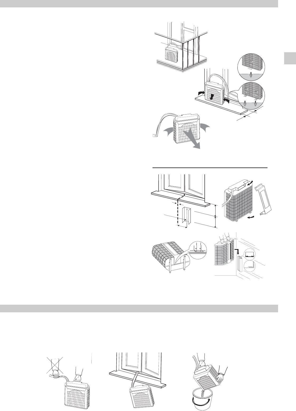
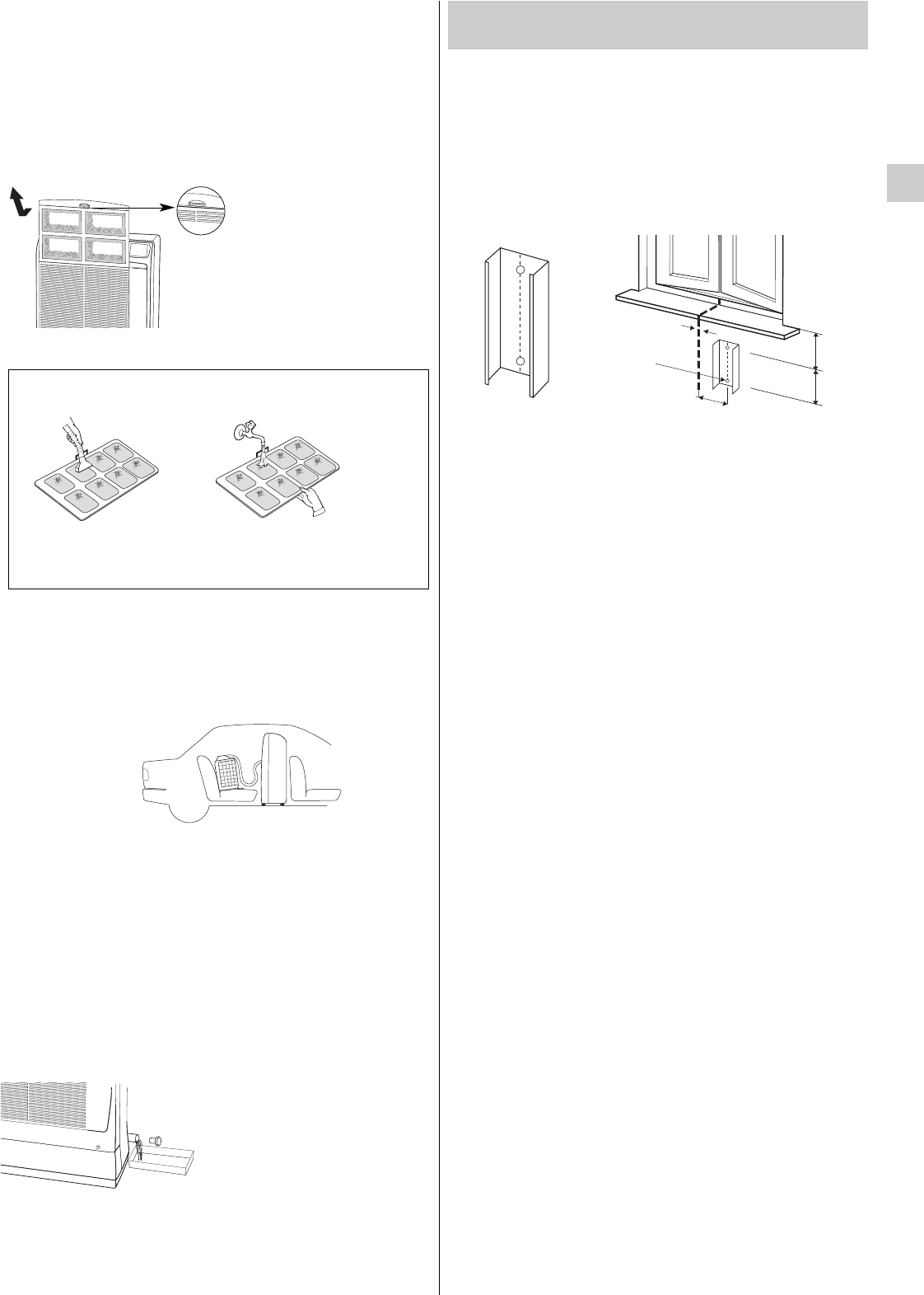
AIR CONDITIONER INSTALLATION. . . . . . . . . . . . . . . . . . . . . . . . . . . . . . . 5
IMPORTANT ADVICE . . . . . . . . . . . . . . . . . . . . . . . . . . . . . . . . . . . . . . . . . . 5
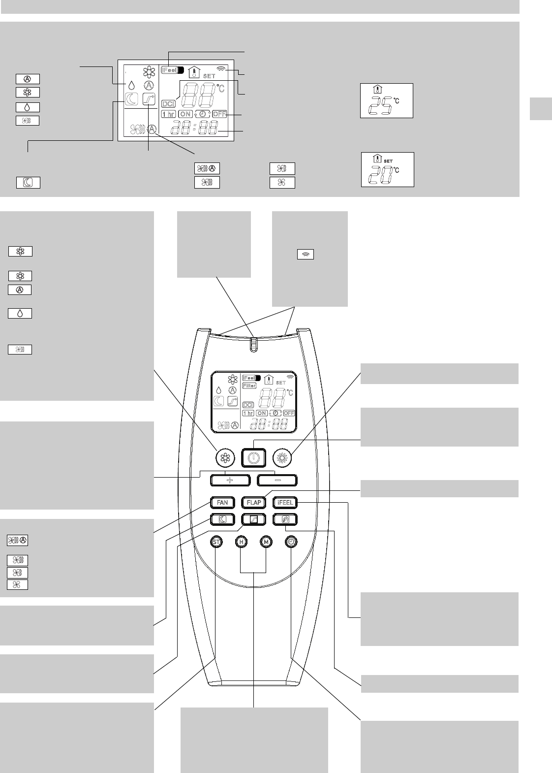
USING THE REMOTE CONTROL UNIT . . . . . . . . . . . . . . . . . . . . . . . . . . . . 6
REMOTE CONTROL UNIT . . . . . . . . . . . . . . . . . . . . . . . . . . . . . . . . . . . . . . 7
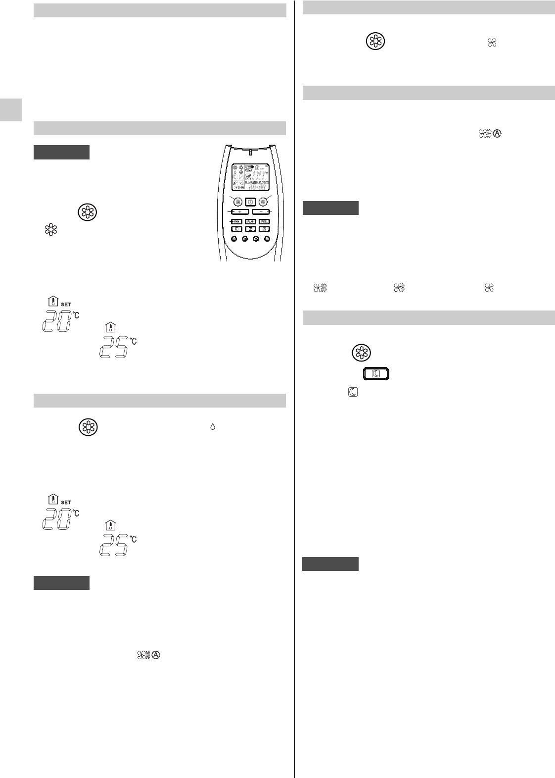
HOW TO SET THE PRESENT TIME. . . . . . . . . . . . . . . . . . . . . . . . . . . . . . . 8
COOLING . . . . . . . . . . . . . . . . . . . . . . . . . . . . . . . . . . . . . . . . . . . . . . . . . . . 8
DEHUMIDIFYING (DRY). . . . . . . . . . . . . . . . . . . . . . . . . . . . . . . . . . . . . . . . 8
FAN ONLY . . . . . . . . . . . . . . . . . . . . . . . . . . . . . . . . . . . . . . . . . . . . . . . . . . . 8
ADJUSTING THE FAN SPEED . . . . . . . . . . . . . . . . . . . . . . . . . . . . . . . . . . 8
NIGHT MODE/ENERGY SAVING . . . . . . . . . . . . . . . . . . . . . . . . . . . . . . . . . 8
HIGH POWER MODE . . . . . . . . . . . . . . . . . . . . . . . . . . . . . . . . . . . . . . . . . . 9
SETTING THE TIMER . . . . . . . . . . . . . . . . . . . . . . . . . . . . . . . . . . . . . . . . . 9
SETTING 1 HR TIMER . . . . . . . . . . . . . . . . . . . . . . . . . . . . . . . . . . . . . . . . . 9
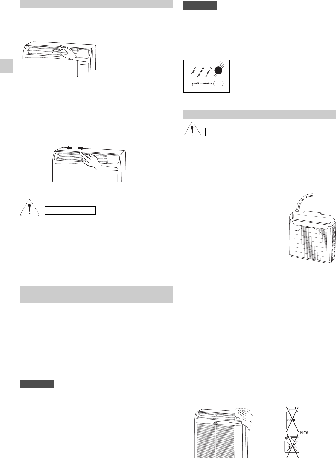
ADJUSTING THE AIR FLOW DIRECTION . . . . . . . . . . . . . . . . . . . . . . . . . 10
OPERATION WITHOUT THE REMOTE CONTROL UNIT . . . . . . . . . . . . . . 10
CARE AND CLEANING. . . . . . . . . . . . . . . . . . . . . . . . . . . . . . . . . . . . . . . . . 10
ACCESSORIES (SUPPLIED ON REQUEST). . . . . . . . . . . . . . . . . . . . . . . . 11
TIPS FOR ENERGY SAVING . . . . . . . . . . . . . . . . . . . . . . . . . . . . . . . . . . . . 12
TROUBLESHOOTINGS . . . . . . . . . . . . . . . . . . . . . . . . . . . . . . . . . . . . . . . . 12
CONTENTS
PRODUCT INFORMATION
If you have problems or questions concerning your Air
Conditioner, you will need the following information. Model
and serial numbers are on the nameplate on the bottom of
the air conditioner.
Model No...........................................................................
Serial No............................................................................
Date of purchase...............................................................
Dealer’s address ...............................................................
Phone number ....................................
ALERT SYMBOLS
The following symbols used in this manual, alert you to
potentially dangerous conditions to users, service personnel
or the appliance:
This symbol refers to a hazard or unsafe practice which
can result in severe personal injury or death.
This symbol refers to a hazard or unsafe practice which
can result in personal injury or product or property damage.
WARNING
CAUTION
EG
SAFETY INSTRUCTIONS
l Read this booklet carefully before using this air
conditioner. If you still have any difficulties or
problems, consult your dealer for help.
l This air conditioner is designed to give you
comfortable room conditions. Use this only for its
intended purpose as described in this Instruction
Manual.
l Never use or store gasoline or other flammable vapour
or liquid near the air conditioner. It is very dangerous.
Moreover, never install electrical equipment, which is
not protected with IPX1 protection (protection against
vertical water drop), under the unit.
l The manufacturer assumes no responsibilities if the safety
regulations or local codes are not observed.
l Never use neither the power main switch or the power
plug to start or stop the air conditioner.
Always use the ON/OFF button.
l Do not stick anything into the air outlet of the air
conditioner. This is dangerous because the fan is
rotating at high speed.
l Do not let children play with the air conditioner.
l Do not cool the room too much if babies or invalids
are present.
l
This air conditioner can be used by children aged
from 8 years and above and persons with reduced
physical, sensory or mental capabilities or lack of
experience and knowledge if they have been given
supervision or instruction concerning use of the air
conditioner in a safe way and understand the hazards
involved.
l Cleaning and user maintenance shall not be made
by children without supervision.
l For safety, be sure to turn the air conditioner off and
also to disconnect the power before cleaning.
WARNING
CAUTION
2
This air conditioner is equipped with cooling, drying and fan functions.
Details on these functions are provided here following; refer on these descriptions when using the air conditioner.
NOTE
EG
3
COOLING
OUTDOOR TEMPERATURE 46°C D.B.
ROOM TEMPERATURE 32°C D.B./23°C W.B.
OUTDOOR TEMPERATURE 19°C D.B.
ROOM TEMPERATURE 19°C D.B./14°C W.B.
OPERATING LIMITS
MAXIMUM CONDITIONS
MINIMUM CONDITIONS
DECLARATION OF CONFORMITY
This product is marked as it satisfies Directives:
Low voltage no. 2006/95/EC.
(Standard: EN60335-2-40:2003 (incl. Corr.:2006) + A11:2004 + A12:2005 + A13:2012
+ A1:2006 + A2:2009 con EN 60335-1:2002 + A11:2004 + A1:2004 + A12:2006 + A2:2006 + A13:2008 + A14:2010
+ A15:2011).
Electromagnetic compatibility no. 2004/108/EC, 92/31 EEC and 93/68 EEC.
(Standard: EN55014-1 (2006) +
A1(2009) + A2(2011), EN 55014-2 (1997) + A1(2001) + A2 (2008), EN 61000-3-2 (2006) + A1(2009) + A2(2009),
EN 61000-3-3 (2008)
RoHS2 no.2011/65/EU.
Regulation (EU) no. 206/2012, of 6 march 2012, concerning the specifications for ecodesign requirements of air
conditioners and fans.
Regulation (EU) no. 626/2011, of 4 may 2011, concerning the labeling indicating the energy consumption of air
conditioners.
This declaration will become void in case of misuse and/or non observance though partial of manufacturer's installation
and/or operating instructions.
Before using the appliance
l Check that the power supply at the location where the
air conditioner is going to be used is 220/240 volt, single
phase.
l For your safety care check periodically the conditions of
the electric supply cable; the electrical connection of the
unit is Y type with cable prepared in a special way; in
case you should notice any damage due to usage, call the
nearest After Sale Service to get the cable replaced.
l Before connecting the air conditioner to a power
socket, make sure that the socket is provided with
an earth connection.
l Verify that the available power supply is sufficient for
running other electrical domestic appliances in use
simultaneously from the same supply. See the data plate
on the unit showing the max. absorbed powers.
l Install a double - pole switch, protected fuses of the
delayed type, upstream the electricity wall socket 10A.
ELECTRICAL REQUIREMENTSINSTALLATION LOCATION
l Do not install this air conditioner where there are
fumes or flammable gases, or in an extremely humid
space such as a green house.
l Do not install the air conditioner where excessively
high heat-generating objects are placed.
l Do not install the air conditioner where the
atmosphere is extremely damp or humid (e.g.
greenhouse or laundry) it could be wetted by drops
of water (i.e. in laundries).
Avoid:
To protect the air conditioner from heavy corrosion, avoid
installing the outdoor unit where salty sea water can splash
directly onto it or in sulphurous air near a spa.
l Make sure that there are no obstacles around the
indoor unit affecting the free circulation of air. Do not
block the air intake and outlet of the unit with
curtains or other.Never put objects on the top of the
unit.
WARNING
l Make sure that circuit breakers, fuses, etc. are of sufficient
capacity to handle start - up current (normally for no longer
than a second).
l All wiring must conform to the local electrical codes.
Consult your dealer or a qualified electrician for details.
WARNING!
The air conditioner is provided with a time-guard system,
which does not allow re-starting of compressor until after
3 minutes from a previous stop.
4
EG
01. Infrared rays remote control unit
02. Monitor panel
03. Supply air deflector
, 4. Return air grille
, 5. Outdoor unit
06. Flexible tube
07. Air filter
08. Electric cable with plug
09. Service tube for condensate evacuation
10. Outdoor unit basket or support
11. Quick coupling cover
MONITOR PANEL
1. TIMER lamp: This lamp lights up when the system is
being controlled by the timer.
2. OPERATION lamp: This lamp lights up during operation.It
blinks once to announce that the remote control signal
has been received and stored.
This lamp flashes and the air conditioner simultaneously
stops during exceeding condensate drainage or because
of malfunctioning of the condensate drainage system.
The OFF position does not disconnect the power. Use the
main power switch to turn off power completely.
WARNING
WATER-LEVEL ALARM
5. Operation button (without remote control): Push the
button to walk through the OFF and COOL operation
modes.
PRODUCT IDENTIFICATION
10
2
7
11
5
6
1
8
3
4
9
1
5
2
4
3
3. STANDBY lamp: this lamp lights up when the air
conditioner is connected to the power and ready to receive
the remote control command.
4. Receiver : receives signals transmitted from the remote
control.
NOTE
The fixed OPERATION lamp and the blinking of TIMER and
STANDBY lamps, indicates that the operating mode selected
( ) is not compatible with the unit. If this happen the air
conditioner does not operate until the correct mode is
selected.
5
POSITIONING OF OUTDOOR UNIT
The outdoor unit must always be kept in vertical position and
levelled. Make sure that there are no obstacles around the
unit affecting the free circulation of air. A lug at the rear bottom
of the unit ensures the minimum distance from the wall (3 cm).
The unit must be kept at a minimum distance of cm. 15
(sidewise) and cm. 80 (frontally) from any walls.
INSTALLATION TYPE A
If your room has a balcony or a window-sill of sufficient depth
(min. 25 cm) you may rest the unit freely onto it. For safety’s
sake, you may anchor the unit to the window-sill using one
M6 x 20 expansion bolt in the slot of the lug at the rear bottom
of the unit.
The flexible tube may easily pass through the balcony door
or window shutters set ajar.
INSTALLATION TYPE B (USING THE SUPPORT)
1. Fix the support guide to the wall below the window sill.
2. Insert the support in the handle of outdoor unit, and turn the
outdoor unit upside down as shown in the picture.
3. Place the support and secure it at the edge of the unit, using
the screws.
4. Insert the support, fixed on the unit, at the guide fixed to
the wall. Make sure it is levelled.
SUPPORT
2 holes ø 10
support
guide
100 min.
200
140
The air conditioner is made of two units interconnected by a
flexible tube. The indoor unit must be placed in the room to be
air conditioned, near a window, a balcony-door or a perimeter
wall. The outdoor unit, that provides to the disposal of heat
and condensation, must be located outside, on a window sill,
on a balcony or hanged to the wall.
Min. 25 cm.
M6 x 20
M6 x 20
AIR CONDITIONER INSTALLATION
TYPE A
TYPE B
EG
IMPORTANT ADVICE
OUTDOOR UNIT
1.When you move the outdoor unit, always hold it by the handle, never pull it by the flexible tube.
2.Never let the outdoor unit hang on the flexible tube.
3.When you recover the outdoor unit after operation, drain away any remaining condensate by tilting the unit.
NO!
NO!
6
OPERATION WITH THE REMOTE CONTROL UNIT
When using the remote control unit, always point the unit
transmitter head directly at the air conditioner receiver.
TEMPERATURE SENSOR SELECTOR
l
Under normal conditions the room temperature is detected
and checked by the temperature sensor placed in the
remote controller (I FEEL icon displayed ).This function
is designed to provide a comfortable room temperature
by transmitting the temperature control command from the
location next to you. When using this function, the remote,
control should always be pointed at the air conditioner,
therefore it should be placed in a position in which it is
visible by the indoor unit (for example, do not put it in a
drawer).
l
It is possible to disable the remote controller room sensor
pressing the I FEEL button. In this case the I FEEL icon
on the remote controller display lights off and the sensor
placed in the air conditioner becomes active.
USING THE REMOTE CONTROL UNIT
INDOOR UNIT
REMOTE CONTROL UNIT
RECEIVER
TRANSMITTER HEAD
EG
l
Insert two AAA alkaline batteries of 1,5 V-DC making
sure that point in the direction marked in the battery
compartment.The displayed time flashes.
Press the SEL TYPE button.
Remote controller is now ready for operation.
l
The batteries last about six months. Depending on how
much you use the remote control unit.
Remove the batteries if you do not use the remote control
unit for more than one month.
Replace the batteries when the remote control unit lamp
fails to light, or when the air conditioner does not receive
the remote control unit signals.
l
The batteries of the remote control contain polluted
substances exhausted batteries must be disposed
according to the laws in force.
HOW TO REMOVE BATTERIES
l Remove the lid.
l Press the battery
toward the negative
end and lift it out by
its positive end (as
shown in the
figure).
l Remove the other
battery in the same
way.
HOW TO INSTALL BATTERIES
l Remove trhe lid in the rear part of the remote control unit
and check the settings of the microswitches as shown
below:
SWITCHES
The remote control unit transmits signals to the indoor
unit each time you press a key and at any temperature
change detected by the IFEEL sensor. In case of
troubles (low batteries, remote control placed in a
position not visible by the indoor unit,...) room
temperature control is automatically switched to the
sensor of the indoor unit. In this case, the temperature
around the remote control unit may differ from the
temperature detected in the air conditioner position.
NOTE
REMOTE CONTROL UNIT
EG
7
DISPLAY
Information is displayed when the remote controller is switched on.
If switched off, only the operating mode, the room temperature and
the clock are shown
Operation mode
Fan speed
High speed
Automatic
Medium speed
Low speed
Displayed when
transmitting data
Set point
temperature
I FEEL mode is active
(remote controller
sensor active)
Timer modes
Automatic
Cooling
Dehumidification
Fan
C
Clock
Room
temperature
Night
mode
HIGH POWER
mode
TRANSMITTER
When you press the
buttons of the remote
control unit, the
mark appears
on the display to
transmit the setting
changes to the
receiver in the air
conditioner.
HOURS AND MINUTES SETTING
BUTTONS
With these buttons is possible to set the
clock and the timer. For details refer to
paragraphs “ SETTING THE HOUR” and
“SETTING THE TIMER”.
TIMER SELECTION BUTTON
Press this button to select the type of timer
to activate. For details refer to paragraph
“SETTING THE TIMER”.
C
TEMPERATURE SETTING BUTTONS
- (cooler)
Press this button to decrease the set
temperature.
+ (warmer)
Press this button to increase the set
temperature.
SENSOR
A temperature
sensor inside the
remote control unit
detects the room
temperature.
CLOK AND TIMER SETTING BUTTON
Press this button in order to:
• set the clock
• set the ON/OFF timer
For details refer to paragraphs “SETTING
THE HOUR” and “SETTING THE TIMER”.
IFEEL/IFEEL C SENSOR SELECTOR
Press this button to modify the active setting
for room temperature detection (from remote
controller to air conditioner and viceversa).
“FAN “ BUTTON (fan speed)
Fan speed is automatically
selected by the microcomputer.
High speed.
Medium speed.
Low speed.
ON/OFF BUTTON
This button turns the air conditioner ON
and OFF.
INACTIVE BUTTON
NIGHT/ECO BUTTON
Press this button in order to select the
NIGHT/ECO mode.
INACTIVE BUTTONS
“HIGH POWER” BUTTON
Press this button in order to select the HIGH
POWER mode.
MODE SELECTOR BUTTON
Press this button to modify the air
conditioner mode.
(cooling)
(automatic)
The air conditioner makes the room cooler.
(dry)
The air conditioner reduces the humidity in
the room.
(fan)
The air conditioner works only as a
circulation fan.
Inverter model
NOT AVAILABLE OPERATION MODE
8
EG
ADJUSTING THE FAN SPEED
HOW TO SET THE PRESENT TIME
COOLING / AUTOMATIC
DEHUMIDIFYING (DRY)
2.
Press the SET H button until the present time hour is
displayed.
Press the SET M button until the present time minutes
are displayed. The display will automatically stop
flashing.
1. Press the button SEL TYPE three times.
The time indication alone flashes.
FAN ONLY
C
Verify that the unit is connected to the
main power and the STANDBY lamp is
light up.
1.Set the selector to COOL (symbol
on the display).
2.Press the +/- buttons (temperature
selection) to set the desired temperature
(the temperature range is between 32 °C
max. and 10 °C min.).
THE DISPLAY SHOWS THE
SELECTED TEMPERATURE.
AFTER 5 SECONDS FROM THE
REQUIRED TEMPERATURE SETTING
THE DISPLAY WILL SHOW THE ROOM
TEMPERATURE AGAIN.
3.Press the FAN button to select the fan speed.
1
3
2
NOTE
2
1
1.Set the button to DRY. The icon is displayed.
2.Press the
+/- buttons (temperature selection)
to set the
desired temperature (the temperature range is between
32 °C max. and 10 °C min.).
THE DISPLAY SHOWS THE
SELECTED TEMPERATURE.
AFTER 5 SECONDS FROM THE
REQUIRED TEMPERATURE SETTING
THE DISPLAY WILL SHOW THE ROOM
TEMPERATURE AGAIN.
l
Use DRY operation when you want to reduce the humidity
in the room.
l
Once the room temperature reaches the set level, the unit
repeats the cycle of turning on and off automatically.
l
During DRY operation, the fan speed is automatically set
(Remote control lamp is ON) to prevent overcooling.
l
Dry operation is not possible if the indoor temperature is
10 °C or less.
NOTE
If you want to make air circulate without any temperature
control, press button until only the fan symbol
appears on the display.
AUTOMATIC
Simply set the FAN selector to the position.A
microcomputer automatically controls the fan speed when
the AUTO mode is selected. When the air conditioner starts
operating, the fan speed varies (high - medium - low - very
low) according to the thermal load of the room.
The automatic speed is not available in FAN ONLY mode.
NOTE
High speed Med. speed Low speed
MANUAL
If you want to manually adjust speed just set the FAN selector
as desired.
NIGHT MODE / ENERGY SAVING
l
This mode enables you to save energy.
1. Set the selector to cool or dry.
2. Press the button.
3. The mark appears on the display. Press the
button again to release the function.
What does the NIGHT mode mean?
When you select the NIGHT mode, the air conditioner will
modify automatically the set temperature after 60 minutes:
it will be raised by 1°C.
This enables you to save energy without sacrificing your
comfort.
During the NIGHT mode the internal fan speed is
automatically lowered and reduces the noise.
NOTA
9
EG
A) HOW TO SET THE ON TIME
1. Press the ST button once.
The ON and time indications flash.
2. Press the H button until the designed
hour is displayed.
Press the M button until the designed
minutes are displayed. The display will
change automatically back to show the
present time after 10 sec.
3. Press the ON/OFF button to start the air
conditioner.
4. Press the button to activate the ON
timer.
B) HOW TO SET THE OFF TIME
1. Press the ST button twice.
The OFF and time indications flash.
2. Press the H button until the designed
hour is displayed.
Press the M button until the designed
minutes are displayed. The display will
change automatically back to show the
present time after 10 sec.
3. Press the ON/OFF button to start the air
conditioner.
4. Press the button two times to
activate the OFF timer.
C) HOW TO SET A PROGRAM FOR
DAILY ON/OFF OPERATION (OR
VICEVERSA)
1. Set the timer ON/OFF as shown in A)
and B).
2. Press the ON/OFF button to start the air
conditioner.
3. Press three times the button to
activate the DAILY timer.
SETTING THE TIMER
After timer setting, press ST button in order to check the
ON/OFF setting time.
NOTE
C
4
2
2
3
1
HIGH POWER MODE
You can select High Power only during cooling mode and
not during dehumidifying (dry) and fan mode. High Power
mode allows to obtain the maximum air conditioner’s
efficiency. The user can choose to activate the High Power
mode, using the remote control unit, after having selected
cooling mode. Under these conditions the air conditioner will
reach its maximum thermal power and consequently also
the maximum electrical consumption and noise. On the
contrary, if you want to obtain the best performance in
efficiency and silentness, High Power mode is not
recommended: let the air conditioner run in normal condition
(factory default program).
To activate High Power mode it is necessary (after having
selected the cooling mode) to press the HIGH POWER
button : the symbol switches on; at this point
the operation lamp (green lamp on the front panel of the air
conditioner) begins blinking slowly, indicating that High
Power mode is activated; press the button again to release
the function: therefore the green lamp will stop blinking and
it will be switched on permanently.
NOTES
l
During the high power operation the room temperature
could not correspond to the set temperature.
l
HIGH POWER program remains set also if you switch
OFF and ON again the air conditioner.
TIMER SETTING PROCEDURE.
l
Press four times the button.The 1
HOUR TIMER mark will appear on the
display.
CANCELLATION PROCEDURE
l
Press the ON/OFF button to turn the air conditioner off.
l
Wait for the indoor unit to stop operating.
l
Press the ON/OFF button again to turn the air conditioner
on.
SETTING THE 1 HOUR TIMER
This function causes the unit to operate for one hour at the
set conditions, regardless of whether the unit is on or off.
l Do not pour water on the unit to clean it. This will damage
the internal components and cause an electric shock
hazard.
l Never use solvents, or chemical agents when cleaning the
indoor unit. Do not wipe the plastic casing using very hot
water.
Casing and Grille
Clean the casing and grille of the indoor unit with a vacuum
cleaner brush, or wipe them with a clean, soft cloth. If these
parts are stained, use a clean cloth moistened with a mild
liquid detergent. When cleaning the grille, be careful not
to force the blades out of place.
10
HORIZONTAL
The horizontal air flow can be adjusted by moving the
vertical blades to the left or right, as indicated in the following
figure.
ADJUSTING THE AIR FLOW DIRECTION
Set vertical blades to the front position during
COOLING/DRY operation if humidity is high.
If the vertical blades are set to the left-most or right-
most position, condensation will form around the air
outlet and drip off.
CAUTION
VERTICAL
Hold the end of the flap and move it up and down to adjust
the vertical air flow.
2. WHEN THE AIR CONDITIONER IS RUNNING
If you want to turn off the air conditioner push the
OPERATION BUTTON until the OPERATION lamp is turned
off.
Power failure during operation.
In the event of power failure, the unit will stop. When the
power is resumed, the unit automatically restarts after 3
minutes.
NOTE
If you have lost the remote control unit or it has troubles,
follow the steps below.
1. WHEN THE AIR CONDITIONER IS STOPPED
If you want to turn on the air conditioner push the
OPERATION BUTTON to select the COOL mode:
OPERATION WITHOUT THE REMOTE
CONTROL UNIT
The air conditioner will start in HIGH fan speed.
The temperature setting is 25°C.
NOTE
CARE AND CLEANING
For safety, be sure to turn the air conditioner off and
also to disconnect the power before cleaning.
l Some metal edges and the
condenser fins are sharp and may
cause injury if handled improperly;
special care should be taken when
you clean these parts.
l Periodically check the outdoor unit
to see if the air outlet or air intake
are clogged up with dirt or soot.
l The condenser and other
components of the outdoor unit must
be cleaned periodically.
Consult your DEALER or AFTER
SALES SERVICE.
OUTDOOR UNIT
(CASING AND CONDENSING COIL)
CAUTION
INDOOR UNIT
T
E
S
T
O
F
F
O
N
OPERATION BUTTON
EG
11
AIR FILTER
The air filter must be cheked at least once every two weeks
operation. Operation with a dirty filter always causes a lower
efficency of the air conditioner and severe product damage.
The filter is located at the back of the intake grille in the front
of the air-conditioner and shall be removed from the upper
side of the unit.
HOW TO REMOVE THE FILTER
FILTER CLEANING
Use a vacuum cleaner to remove light dust. If there is
sticky dust on the filter, wash the filter in lukewarm, soapy
water, rinse it in clean water, and dry it.
TRANSPORT
Preferably keep the air conditioner in the vertical position
during transportation. If this is not possible, then lay it on
one side; when at destination put the air conditioner back in
the vertical position and wait at least 10 minutes before using
it.
STORAGE
If you are not going to use the air-conditioner for a long period,
clean the air filters, evacuate the condensate from the indoor
unit through the drain hose at the unit back side. Do not
disconnect the flexible tube, unless you are obliged to do it:
in that case protect the open halves of the couplings with the
plugs supplied as accessories, that must be tightened with
a spanner. Do not put heavy objects on the top of the unit,
and protect it with a cloth or a plastic bag.
CONDENSATE DRAIN PIPE
EG
ACCESSORIES (SUPPLIED ON
REQUEST)
SUPPLEMENTARY SUPPORT GUIDE KIT FOR
OUTDOOR UNIT
2 holes ø 10
100 min.
200
SUPPORT GUIDE
If you want to utilise the air conditioner in several rooms, it
is possible to buy varies support guides for the installation
of outdoor unit.
12
The use of portable telephones near the air-conditioner
may cause disturbance to its normal operation and must
be avoided. In case abnormal operation is noticed,
(OPERATION lamp lights but outdoor unit will not run) to
restore normal operation turn-off electric supply for 60
seconds at least, by disconnecting the main switch or
the wall plug, then start again the air-conditioner.
The blinking OPERATION lamp, together with the stop of
the air conditioner for a short time are due to the exceeding
condensate drainage.
If the OPERATION lamp goes on blinking and the air
conditioner definitely stops means that the condensate
pump is not working or that the condensate drain pipe in
the flexible connection pipe is obstructed; in this case
contact the AFTER SALE SERVICE.
In case of emergency the air conditioner can work by
draining the condensate from the back little pipe into a
rather short container: extract the little pipe and remove
the cap.
If your air conditioner does not work properly, first check
the following points before requesting service.
If it still does not work properly, contact your dealer or
service center.
TIPS FOR ENERGY SAVING
DO NOT:
l Block the air intake and outlet of the unit.
If they are obstructed, the unit will not work well, and
may be damaged.
l Let direct sunlight into the room. Use sunshades, blind
or curtain.
DO:
l Always try to keep the air filter clean. A clogged filter
will impair the performance of the unit.
l To prevent conditioned air from escaping, keep windows,
doors and any other openings closed.
TROUBLESHOOTING
Trouble: the air conditioner does not run at all.
Possible cause:
1. Power failure.
2. Leakage breaker tripped.
3. Line voltage is too low.
4. Operation button is OFF.
5. Batteries in remote control unit have run down.
Remedy:
1. Restore power.
2. Contact service center.
3. Consult your electrician or dealer.
4. Press the button again.
5. Replace batteries.
Trouble: Compressor runs but soon stops.
Possible cause:
1. Obstruction in front of condenser coil.
Remedy:
1. Remove obstruction.
Trouble: Poor cooling performance.
Possible cause:
1. Dirty or clogged air filter.
2. Heat source or many people in room.
3. Doors and/or windows are open.
4. Obstacle near air intake or air discharge port.
5. Thermostat is set too high.
Remedy:
1. Clean air filter to improve airflow.
2. Eliminate heat source if possible.
3. Shut them to keep the heat or cold out.
4. Remove it to ensure good airflow.
5. Set the temperature lower.
Trouble: Clicking sound is heard from the air conditioner.
Possible cause:
1. Any plastic parts may expand or shrink due to a sudden
temperature change. In this event, a clicking sound may
occur.
Remedy:
1. This is normal, and the sound will disappear when an
even temperature is settled.
NOTE
The fixed OPERATION lamp and the blinking of TIMER and
STANDBY lamps, indicates that the operating mode selected
( ) is not compatible with the unit. If this happen the air
conditioner does not operate until the correct mode is
selected.
POSSIBLE CAUSE REMEDY
STANDBY OPERATION TIMER
F F O Defective indoor air sensor Contact service centre
O F F Defective indoor air coil sensor Contact service centre
F O O Defective compressor discharge temperature sensor Contact service centre
F l O Malfuctioning of electronic PCB (current protection) Contact service centre
F O l Malfuctioning of electronic PCB (temperature protection) Contact service centre
F l l Malfuctioning of PFC (power factor correction system) Contact service centre
O F O Malfunctioning of the condensate drainage system Contact service centre
LEDS
AUTO-DIAGNOSIS
O = LED OFF
l
= LED ON
F = Flashing LED
EG
13
INFORMATION FOR CORRECT DISPOSAL OF THE PRODUCT IN ACCORDANCE WITH THE EUROPEAN
DIRECTIVE 2012/19/EU
At the end of its working life this equipment must not be disposed of as an household waste.
It must be taken to special local community waste collection centres or to a dealer providing this service.
Disposing of an electrical and electronic equipment separately avoids possible negative effects on the environment
and human health deriving from an inappropriate disposal and enables its components to be recovered and recycled
to obtain significant savings in energy and resources.
In order to underline the duty to dispose of this equipment separately, the product is marked with a crossed-out dustbin.
INFORMATION FOR CORRECT DISPOSAL OF THE BATTERY IN ACCORDANCE WITH THE EUROPEAN
DIRECTIVE 2006/66/EC
Please replace battery when its electricity charge is used up: please do not eliminate this battery together with normal
household waste. It must be taken to special local community waste collection centres or to a dealer providing this
service. Disposing of a battery separately avoids possible negative effects on the environment and human health
deriving from an inappropriate disposal and enables its components to be recovered and recycled to obtain significant
savings in energy and resources. In order to underline the duty to dispose of this equipment separately, the battery is
marked with a crossed-out dustbin.
REGULATION (EU) No. 517/2014 - F-GAS
The unit contains R410A, a fluorinated greenhouse gas with a global warming potential (GWP) of
2087.50. Do not release R410A into the atmosphere.
EG
Wires color legend
Legenda colori fili elettrici
Légende des couleurs des fils électriques
Beschriftung der Leitungs-Farben
Leyenda de los colores de los cable electricos
PPiivvnnaakkaa"" ccrrwwmmaavvttwwnn hhlleekkttrriikkwwvvnn kkaallwwddiivvwwnn
EG I F D E GR
BLK BLACK NERO NOIR SCHWARZ NEGRO MAURO
BLU BLUE BLU BLEU BLAU AZUL MPLE
BRN BROWN MARRONE MARRON BRAUN MARRON KAFE
GRN / YEL GREEN / YELLOW VERDE / GIALLO VERT / JAUNE GRÜN / GELB VERDE / AMARILLO PRASINO / KITRINO
GRY GREY GRIGIO GRIS GRAU GRIS GKRIZO
ORG ORANGE ARANCIONE ORANGE ORANGE ANARANJADO PORTOKALI
PNK PINK ROSA ROSE ROSA ROSA ROZ
RED RED ROSSO ROUGE ROT ROJO KOKKINO
VLT VIOLET VIOLA VIOLET VIOLETT VIOLETA MWB
WHT WHITE BIANCO BLANC WEISS BLANCO ASPRO
YEL YELLOW GIALLO JAUNE GELB AMARILLO KITRINO
E
lectric wiring diagrams’ symbols /
Simboli schemi elettrici
/ Symboles des schemas électriques
Legende: Schaltplan
/ Símbolos de los esquemas eléctricos /
SSuummbblloovvllwwnn HHLLEEKKTTRRIIKKOO DDIIAAGGRRAAMMMMAA TTWWNN SSUUSSTTHHMMAATTWWNN
SYMBOL EG I F D E GR
PC CONDENSATE PUMP POMPA SCARICO CONDENSA POMPE D’EVACUATION DES CONDENSATS
KONDENSWASSERAUSLASS-PUMPE
BOMBADE DESCARGA DELLIQUIDO DE COND.
ANTLIA APOSTRAGGISHS
CM COMPRESSOR MOTOR MOTORE COMPRESSORE MOTEUR DE COMPRESSEUR KOMPRESSORMOTOR MOTOR DEL COMPRESOR SUMPIESTHS
C1, 2, 3 CAPACITOR CONDENSATORE CONDENSATEUR KONDENSATOR CONDENSADOR SUMPUKNWTHS
DEF THERMO DEFROST THERMOSTAT TERMOSTATO SBRINATORE THERMOSTAT DE DÉGIVRAGE ENTFROSTER-THERMOSTAT TERMOSTATO DE DESCONGELACIÓN QERMOSTATHS APOYUXHS
IND. U. INDOOR UNIT UNITA' INTERNA UNITÉ INTÉRIEURE INNENEINHEITEN UNIDADES INTERNAS ESWTERIKES MONADES
OUTD. U. OUTDOOR UNIT UNITA' ESTERNA UNITÉ EXTÉRIEURE AUßENEINHEITEN UNIDADES EXTERNAS EXWTERIKES MONADES
FMO OUTDOOR FAN MOTOR MOTORE ESTERNO VENTOLA MOTEUR DE VENTILATEUR EXTÉRIEUR AUSSENLÜFTERMOTOR MOTOR EXTERIOR DE LATURBINA EXWTERIKOS ANEMISTHRAS
FMI INDOOR FAN MOTOR MOTORE INTERNO VENTOLA MOTEUR DE VENTILATEUR INTÉRIEUR INNENLÜFTERMOTOR MOTOR INTERIOR DE LATURBINA ESWTERIKOS ANEMISTHRAS
IND. ASSY INDICATOR ASSY GRUPPO INDICATORI ENSEMBLE INDICATEUR ANZEIGE-BAUGRUPPE GRUPPO DE INDICADORES SET ENDEIKTIKOU
AL WATER LEVELALARM SPIAALLAR. LIV. ACQUA VOYANT D'ALARME DU NIVEAU WASSERTSAND-NOTANZEIGE PILOTO ALARMA NIVEL AGUA LUCNIA SUNAGERMOU ETAQMHS NEROU
NF NOISE FILTER FILTRO RUMORE FILTRE DE BRUIT LÄRMSCHUTZFILTER FILTRO DEL RUIDO FILTRO QORUBOU
OLR OVERLOAD RELAY RELÉ SOVRACCARICO RELAIS DE SURCHARGE ÜBERLASTRELAIS RELÉ DE SOBRECARGA RELE UPERFORTWSHS
PCB1, 2 CONTROLLER SCHEDA ELETT CONTRÔLEUR STEUERGERÄT CONTROLADOR ELEGKTHS
PR POWER RELAY RELÉ ALIMENTAZIONE RELAIS D'ALIMENTATION LEISTUNGSRELAIS RELÉ DE ALIMENTACIÓN RELE ISCUOS
FS SAFETY FLOAT SWIT. INT. SICUREZZAA GALL. INTERR. DE SECURITE A FLOTTEUR SCHWEMM-SCHUTZSCHALTER
INTERR. DE SEGURIDAD DE FLOTADOR
DIAKOPTHS ASFALEIAS ME PLWTHRA
SW.ASSY SWITCH ASSY GRUPPO INTERRUTTORI ENSEMBLE INTERRUPTEUR SCHALTER-BAUGRUPPE GRUPPO DE INTERRUPTORES SET DIAKOPTH
TH1, 2 THERMISTOR TERMISTORE THERMISTOR THERMISTOR TERMISTOR QERMOSTATHS
TP TERMINAL PLATE PIASTRA TERMINALI BORNIER KLEMMENPLATTE PLACA DE LOS TERMINALES AKRODEKTHS
TR POWER TRANSFORMER TRASFORMATORE DI POTENZA TRANSFORMATEUR DE PUISSANCE NETZTRANSFORMATOR TRANSFORMADOR DE POTENCIA METASCHMATISTHS ISCUOS
20S 4-WAY VALVE VALVOLA 4 VIE VANNE 4 VOIES 4-WEG-VENTIL VALVULA DE 4 VIAS BAGBIDA 4 DIEUQUNSEXWN
RA STARTING RELAY RELÈ AVVIAMENTO RELAIS DE MISE EN MARCHE START - RELAIS RELE DE ARRANQUE RELE EKKINETS
LC CURRENT LIMITER LIMITATORE CORRENTE LIMITEUR DE COURANT STROM BEGRENZER LIMITADOR DE CORRIENTE RUQMISTHS REUMATOS
RP PUMP RELAY RELÈ POMPA PUMPE RELAIS PUMPE - RELAIS RELE BOMBA DE AGUA RELE LNTLIA
INDUCTOR INDUCTOR INDUTTORE INDUCTOR INDUCTOR INDUCTOR INDUCTOR
EMI FILTER EMIFILTER FILTRO DI RETE FILTRE DE RESEAU NETZFILTER FILTRO DE RED FILTRO DE RED
S.A.C. - Printed in italy
Via Varese, 90 - 21013 Gallarate - Va - Italy
Tel. +39 0331 755111 - Fax +39 0331 776240
www.argoclima.com
1

Hulp nodig? Stel uw vraag in het forum

Spelregels

Misbruik melden

Gebruikershandleiding.com neemt misbruik van zijn services uitermate serieus. U kunt hieronder aangeven waarom deze vraag ongepast is. Wij controleren de vraag en zonodig wordt deze verwijderd.

Product:

Bijvoorbeeld antisemitische inhoud, racistische inhoud, of materiaal dat gewelddadige fysieke handelingen tot gevolg kan hebben.

Bijvoorbeeld een creditcardnummer, een persoonlijk identificatienummer, of een geheim adres. E-mailadressen en volledige namen worden niet als privégegevens beschouwd.

Spelregels forum

Om tot zinvolle vragen te komen hanteren wij de volgende spelregels:

Belangrijk! Als er een antwoord wordt gegeven op uw vraag, dan is het voor de gever van het antwoord nuttig om te weten als u er wel (of niet) mee geholpen bent! Wij vragen u dus ook te reageren op een antwoord.

Belangrijk! Antwoorden worden ook per e-mail naar abonnees gestuurd. Laat uw emailadres achter op deze site, zodat u op de hoogte blijft. U krijgt dan ook andere vragen en antwoorden te zien.

Abonneren

Abonneer u voor het ontvangen van emails voor uw Argo Ulisse 13-DCI bij:


U ontvangt een email met instructies om u voor één of beide opties in te schrijven.


Ontvang uw handleiding per email

Vul uw emailadres in en ontvang de handleiding van Argo Ulisse 13-DCI in de taal/talen: Engels als bijlage per email.

De handleiding is 1,79 mb groot.


U ontvangt de handleiding per email binnen enkele minuten. Als u geen email heeft ontvangen, dan heeft u waarschijnlijk een verkeerd emailadres ingevuld of is uw mailbox te vol. Daarnaast kan het zijn dat uw internetprovider een maximum heeft aan de grootte per email. Omdat hier een handleiding wordt meegestuurd, kan het voorkomen dat de email groter is dan toegestaan bij uw provider.

Stel vragen via chat aan uw handleiding

Stel uw vraag over deze PDF

Andere handleiding(en) van Argo Ulisse 13-DCI

Argo Ulisse 13-DCI Installatiehandleiding - Deutsch - 28 pagina's

Argo Ulisse 13-DCI Gebruiksaanwijzing - Deutsch - 15 pagina's

Argo Ulisse 13-DCI Installatiehandleiding - English, Français - 28 pagina's

Argo Ulisse 13-DCI Gebruiksaanwijzing - Français - 15 pagina's

Argo Ulisse 13-DCI Installatiehandleiding - Italiano, Português, Espanõl - 28 pagina's


Uw handleiding is per email verstuurd. Controleer uw email

Als u niet binnen een kwartier uw email met handleiding ontvangen heeft, kan het zijn dat u een verkeerd emailadres heeft ingevuld of dat uw emailprovider een maximum grootte per email heeft ingesteld die kleiner is dan de grootte van de handleiding.

Er is een email naar u verstuurd om uw inschrijving definitief te maken.

Controleer uw email en volg de aanwijzingen op om uw inschrijving definitief te maken

U heeft geen emailadres opgegeven

Als u de handleiding per email wilt ontvangen, vul dan een geldig emailadres in.

Uw vraag is op deze pagina toegevoegd

Wilt u een email ontvangen bij een antwoord en/of nieuwe vragen? Vul dan hier uw emailadres in.


Info