2
IMPORTANT!
Veuillez lire ce qui suit avant de commencer
Ce système de conditionnement de l'air répond à des
normes strictes de fonctionnement et de sécurité. En tant
qu'installateur ou ingénieur de maintenance, une partie
importante de votre travail est d'installer ou d'entretenir le
système de manière à ce qu'il fonctionne efficacement en
toute sécurité.
Pour effectuer une installation sûre et obtenir un
fonctionnement sans problème, il vous faut:
• Lire attentivement cette brochure d'information avant de
commencer.
• Procéder à chaque étape de l'installation ou de la
réparation exactement comme il est indiqué.
• Respecter toutes les réglementations électriques locales,
régionales et nationales.
• Observer toutes les recommandations de prudence et
de sécurité données dans cette notice.
• Pour l'alimentation de l'appareil utiliser une ligne électrique
dédiée.
Ce symbole fait référence à une pratique dangereuse ou
imprudente qui peut entraîner des blessures personnelles
ou la mort.
Ce symbole fait référence à une pratique dangereuse ou
imprudente qui peut entraîner des blessures personnelles
ou des dégâts matériels, soit à l'appareil, soit aux
installations.
Si nécessaire, demandez que l'on vous prête assistance
Ces instructions suffisent à la plupart des sites d'installation
et des conditions de maintenance. Si vous avez besoin
d'assistance pour résoudre un problème particulier,
adressez-vous à notre service aprés vente ou à votre
revendeur agréé pour obtenir des instructions
supplémentaires.
Dans le cas d'une installation incorrecte
Le fabricant ne sera en aucun cas responsable dans le cas
d'une installation ou d'une maintenance incorrecte, y compris
dans le cas de non-respect des instructions contenues dans
ce document.
PRECAUTIONS PARTICULIERES
• Pour l’installation: raccorder les liaisons frigorifiques, puis
les liaisons électriques.
Pour le démontage: procéder de manière inverse.
Lors du câblage
UNE DECHARGE ELECTRIQUE PEUT
ENTRAINER UNE BLESSURE PERSONNELLE
GRAVE OU LA MORT. SEUL UN ELECTRICIEN
QUALIFIE ET EXPERIMENTE DOIT EFFECTUER
LE CABLAGE DE CE SYSTEME.
• Ne mettez pas l'appareil sous tension tant que tout le
système de câbles et de tuyaux n'est pas terminé ou
rebranché et vérifié, pour assurer la mise à la terre.
• Des tension électriques extrêmement dangereuses sont
utilisées dans ce système. Veuillez consulter attentivement
le schéma de câblage et ses instructions lors du câblage.
Des connexions incorrectes ou une mise à la terre
inadéquate peuvent entraîner des blessures
accidentelles ou la mort.
• Effectuez la mise à la terre de l'appareil en respectant
les réglementations électriques locales.
• Le câble jaune/vert ne peut en aucun cas être utilisé pour
toute autre connexion que celle de la mise à la terre.
• Serrez fermement toutes les connexions. Un câble mal
fixé peut entraîner une surchauffe au point de connexion
et présenter un danger potentiel d'incendie.
• Il ne faut en aucun cas laisser les câbles toucher la
tuyauterie du réfrigérant, le compresseur ou toute pièce
mobile.
• N’utilisez pas de câble multiconducteur pour le câblage
des lignes d’alimentation électrique et celles de
commande. Utilisez des câbles séparés pour chaque type
de ligne.
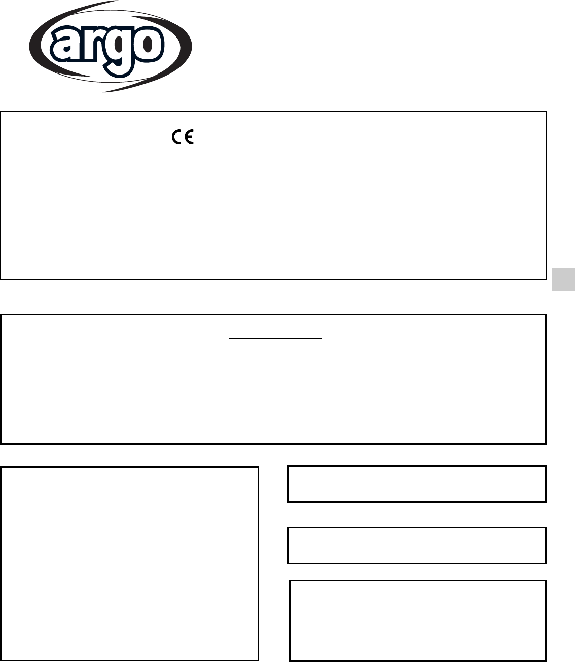
Lors du transport
Soyez prudent lorsque vous soulevez et déplacez les
appareils intérieur et extérieur. Demandez à un collègue
de vous aider, et pliez les genoux lors du levage afin de
réduire les efforts sur votre dos. Les bords acérés ou les
ailettes en aluminium mince se trouvant sur le climatiseur
risquent de vous entailler les doigts.
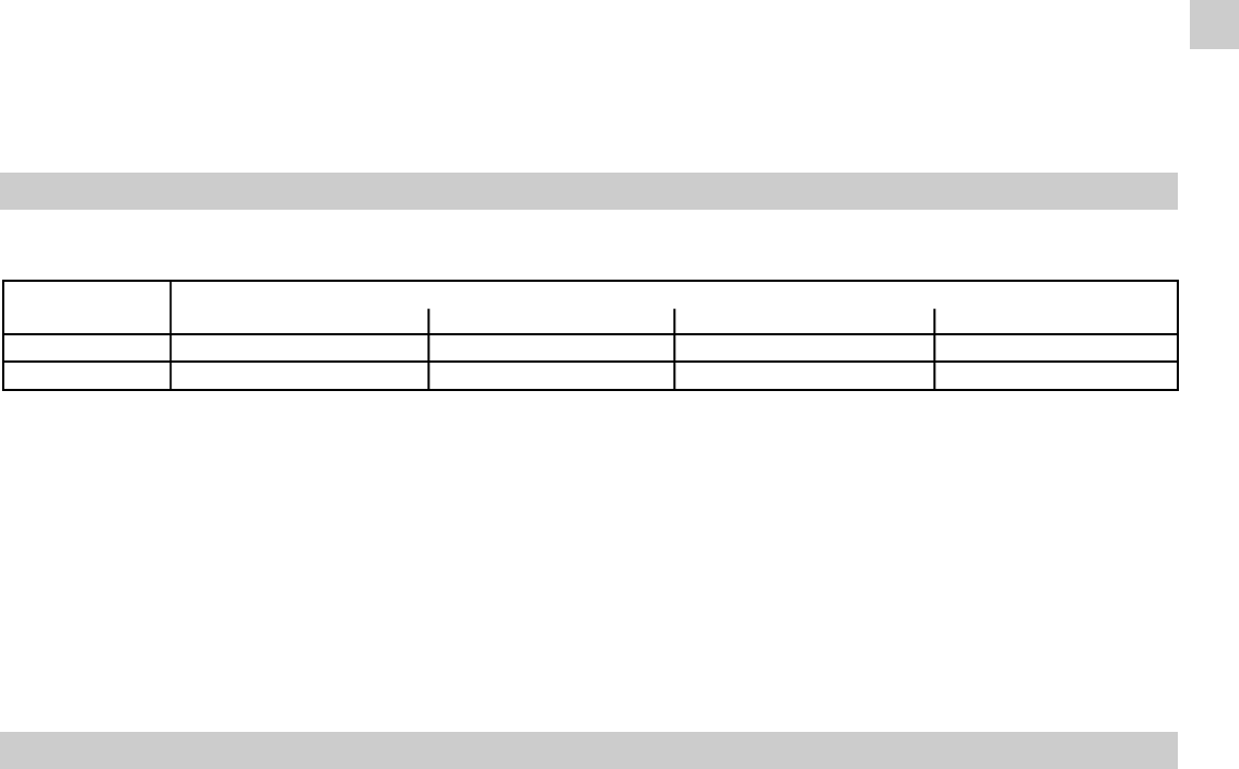
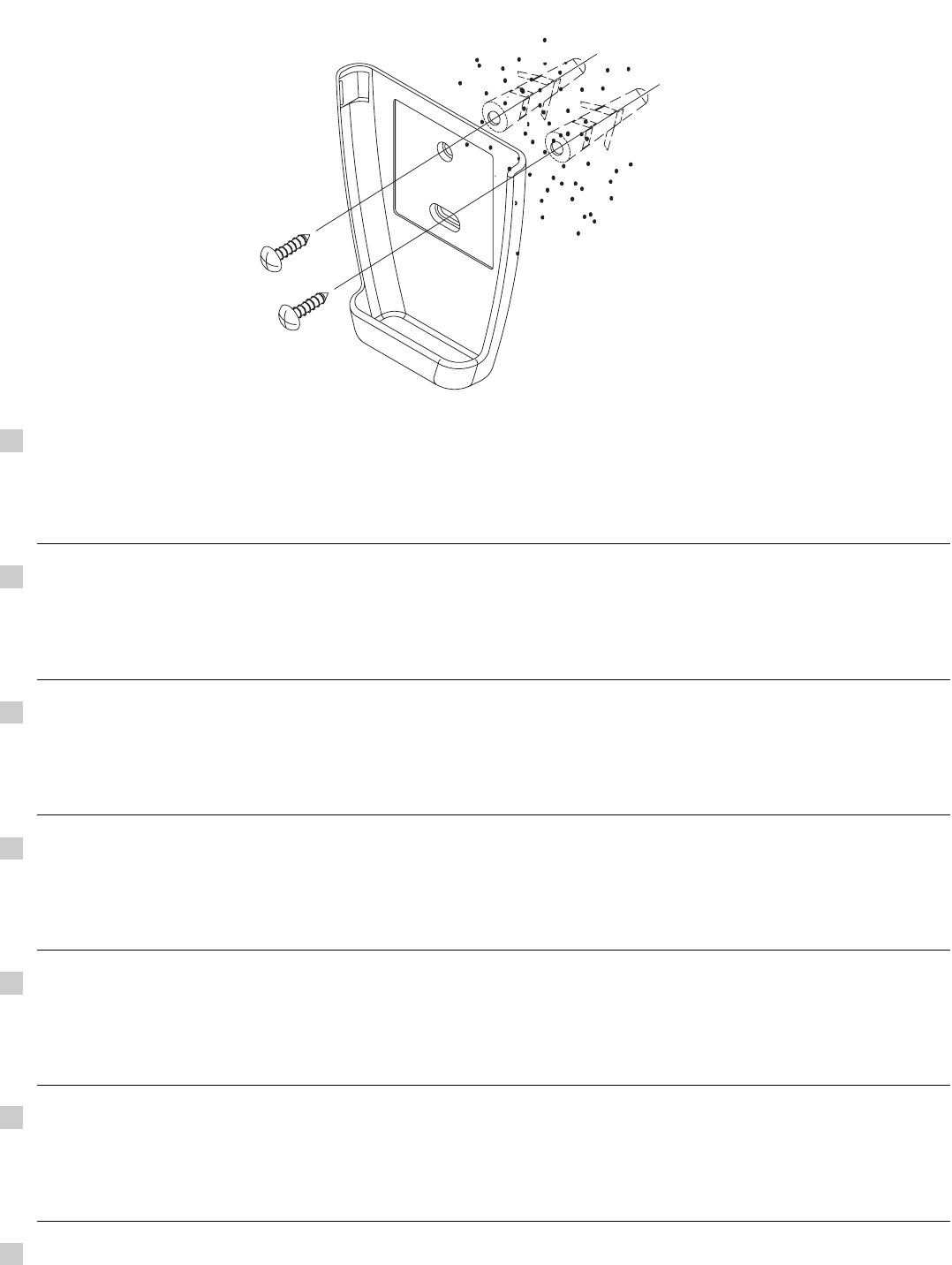
Lors de l'installation...
... dans un plafond ou un mur
Assurez-vous que le plafond ou le mur sont suffisamment
solides pour supporter le poids de l'appareil. Il peut être
nécessaire de construire un solide châssis en bois ou en
métal pour offrir un support supplémentaire.
... dans une pièce
Isolez correctement tout tuyau circulant à l'intérieur d'une
pièce pour éviter que de la condensation ne s'y dépose et
ne goutte, ce qui pourrait endommager les murs et les
planchers.
... dans des endroits humides ou sur des surfaces
irrégulières
Utilisez une plate-forme surélevée pour offrir une base
solide et régulière à l'appareil extérieur.
Ceci permettra d'éviter des dégâts causés par l'eau et des
vibrations anormales.
... dans une zone exposée à des vents forts
Ancrez solidement l'appareil extérieur avec des boulons et
un châssis en métal. Réalisez un déflecteur efficace.
... dans une zone neigeuse (pour le système du type
reversible)
Installez l'appareil extérieur sur une plate-forme surélevée
à un niveau supérieur à l'amoncellement de la neige.
Réalisez des évents à neige.
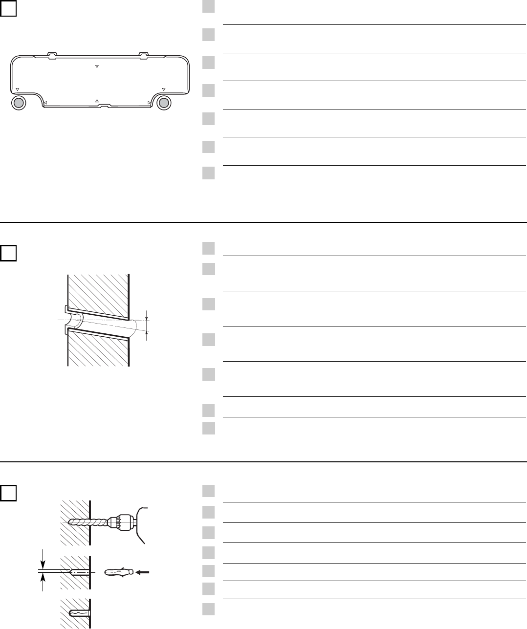
Lors de la connexion des tuyaux de réfrigération
• Limitez au maximum la longueur des tuyaux.
• Les raccordements sont de type flare.
• Appliquez de l’huile frigorifique sur les surfaces de contact
avant de les connecter, puis serrez l'ecrou avec une clé
dynamométrique pour effectuer une connexion sans fuite.
• Recherchez soigneusement la présence de fuites avant
d'effectuer l'essai de fonctionnement.
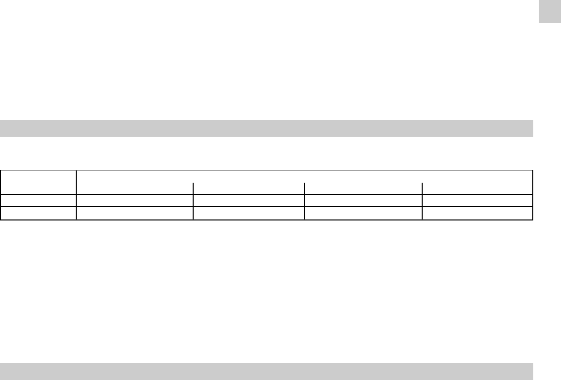
NOTE:
Selon le type du système, les tuyaux de gaz et de liquide
peuvent être petits ou gros. Par conséquent, afin d'éviter
toute confusion, le tuyau de réfrigérant de votre modèle
particulier est dénommé "petit" pour le liquide et "gros" pour
le gaz.
Lors de la maintenance
• Interrompre l'alimentation électrique sur le commutateur
principal avant d'ouvrir l'appareil pour vérifier ou réparer
le câblage et les pièces électriques.
• Veillez à maintenir vos doigts et vos vêtements éloignés
de toutes les pièces mobiles.
• Nettoyez le site lorsque vous avez fini, en pensant à
vérifier que vous n'avez laissé aucune ébarbure de métal
ou morceau de câble à l'intérieur de l'appareil dont vous
avez effectué la maintenance.
• Aèrez la pièce pendant l'installation et l'essai du circuit
réfrigérant; assurez-vous que, après l'installation, des
fuites de gaz réfrigérant ne se produisent pas, puisque
le contact avec des flammes ou des sources de chaleur
peut être toxique et très dangereux.
DANGER
PRUDENCE
DANGER
FG