MPC Studio .......................................................................................................................................... 25
Top Panel ........................................................................................................................................ 25
Starting Up ........................................................................................................................................... 31
Creating a Drum Kit ............................................................................................................................ 32
Recording a Drum Sequence ............................................................................................................. 33
Organizing Samples and Editing Note Events ................................................................................. 34
Making Basic Sound Edits ................................................................................................................. 36
Recording a Bass Track ..................................................................................................................... 37
Creating a Song .................................................................................................................................. 41
Exporting the Song ............................................................................................................................. 41
Other Features Explained ................................................................................................................... 42
General Features ................................................................................................................................. 53
Adjusting the Controls ..................................................................................................................... 53
Program Types ................................................................................................................................ 55
About Programs ............................................................................................................................................. 55
Manually Entering and Editing Automation ...................................................................................................... 88
List View .......................................................................................................................................... 89
Entering and Editing Events ............................................................................................................................ 91
File Menu ....................................................................................................................................................... 95
Edit Menu ...................................................................................................................................................... 98
Metronome Menu ......................................................................................................................................... 106
Time Correct Menu ...................................................................................................................................... 107
Tools Menu .................................................................................................................................................. 109
View Menu ................................................................................................................................................... 110
Help Menu ................................................................................................................................................... 111
5
Main Mode ......................................................................................................................................... 112
Program Mode ............................................................................................................................................. 114
FX Mode ...................................................................................................................................................... 116
Pad Bank Section .......................................................................................................................... 117
Anatomy of an Envelope ............................................................................................................................... 143
Pad Play Modes Section (Drum Programs Only) .......................................................................... 144
Record Arm ................................................................................................................................................. 176
Sample Rec and Sample Stop ...................................................................................................................... 178
Direct Record ............................................................................................................................................... 179
Project Information ........................................................................................................................ 180
Pad Section ................................................................................................................................................. 187
Process Section ........................................................................................................................................... 190
Project Information ....................................................................................................................................... 192
Chop Mode .................................................................................................................................... 193
Pad Section ................................................................................................................................................. 196
Chop To Section .......................................................................................................................................... 199
Process Section ........................................................................................................................................... 200
Project Information ....................................................................................................................................... 203
Song Mode......................................................................................................................................... 204
Program Insert Effects .................................................................................................................................. 229
Bit Reducers .................................................................................................................................. 271
Other .............................................................................................................................................. 272
This effect is a static filter without modulation.
Parameter Value Range Default Value Q-Link Knob Number
Frequency 10–19999 Hz 1500 Q13
Resonance 0–100 0 Q9
LP Filter Sweep
This effect is a low-pass filter with its cutoff frequency modulated by an LFO.
Parameter Value Range Default Value Q-Link Knob Number
Dry/Wet 0–100 (dry–wet) 80 Q13
Low Frequency 0–100 0 Q9
High Frequency 0–100 100 Q5
Resonance 0–100 33 Q1
Rate 0–100 10 Q14
261
LP Filter Sync
This effect is a low-pass filter with its cutoff frequency modulated by an LFO.
Parameter Value Range Default Value Q-Link Knob Number
Dry/Wet 0–100 (dry–wet) 100 Q13
Low Frequency 0–100 0 Q9
High Frequency 0–100 100 Q5
Resonance 0–100 50 Q1
Rate 8 bars – 1/32 1/4 Q14
LP Shelving Filter
This filter differs from the standard filter type, as it attenuates all frequencies after the cutoff point
equally.
Parameter Value Range Default Value Q-Link Knob Number
Frequency 10–19999 Hz 1500 Q13
Resonance 0–100 0 Q9
Gain -18.0 – 18.0 dB 0.0 Q5
262
Parametric EQs
Options: PEQ 2-Band, 2-Shelf and PEQ 4-Band.
PEQ 2-Band, 2-Shelf
This effect is a combination of one two-band parametric equalizer and two shelving filters.
Parameter Value Range Default Value Q-Link Knob Number
Low Frequency 22–1000 Hz 220 Q13
Frequency 1 82–3900 Hz 820 Q9
Frequency 2 220–10000 Hz 2200 Q5
High Frequency 560–19999 Hz 5600 Q1
Q1 0–100 0 Q10
Q2 0–100 0 Q6
Low Gain -18.0 – 18.0 dB 0.0 Q15
Gain 1 -18.0 – 18.0 dB 0.0 Q11
Gain 2 -18.0 – 18.0 dB 0.0 Q7
High Gain -18.0 – 18.0 dB 0.0 Q3
263
PEQ 4-Band
This effect is a powerful four-band parametric equalizer with four independent EQ ranges.
Parameter Value Range Default Value Q-Link Knob Number
Low Frequency 22–1000 Hz 220 Q13
Frequency 1 82–3900 Hz 820 Q9
Frequency 2 220–10000 Hz 2200 Q5
High Frequency 560–19999 Hz 5600 Q1
Q1 0–100 5 Q14
Q2 0–100 5 Q10
Q3 0–100 5 Q6
Q4 0–100 5 Q2
Gain 1 -18.0 – 18.0 dB 0.0 Q15
Gain 2 -18.0 – 18.0 dB 0.0 Q11
Gain 3 -18.0 – 18.0 dB 0.0 Q7
Gain 4 -18.0 – 18.0 dB 0.0 Q3
264
Distortions
Options:Distortion Amp, Distortion Fuzz, Distortion Grimey, Distortion Overdrive, and Distortion
Custom.
Distortion Amp
This effect is designed to reproduce the sound of a tube amplifier at high volumes.
Parameter Value Range Default Value Q-Link Knob Number
Dry/Wet 0–100 (dry–wet) 100 Q13
Drive 0–100 50 Q9
Tone 0–100 50 Q5
Dynamics 0–100 50 Q1
Output 0–100 50 Q14
Distortion Fuzz
This popular effect uses hard clipping of the audio signal, which, at extreme settings, can turn a
standard waveform into a square wave, producing a "razor" effect.
Parameter Value Range Default Value Q-Link Knob Number
Dry/Wet 0–100 (dry–wet) 100 Q13
Drive 0–100 50 Q9
Output 0–100 50 Q5
Low 0–100 50 Q14
Low-Mid 0–100 50 Q10
High-Mid 0–100 50 Q6
High 0–100 50 Q2
265
Distortion Grimey
This is a unique distortion effect that distorts a frequency range in a selectable band.
Parameter Value Range Default Value Q-Link Knob Number
Dry/Wet 0–100 (dry–wet) 100 Q13
Drive 0–100 50 Q9
Grime 0–100 50 Q5
Center 0–100 50 Q1
Width 0–100 50 Q14
Resonance 0–100 50 Q10
Output 0–100 50 Q6
Distortion Overdrive
This distortion is designed to sound like a mildly distorting amplifier at medium volumes. It is the
smoothest distortion type available.
Parameter Value Range Default Value Q-Link Knob Number
Dry/Wet 0–100 (dry–wet) 100 Q13
Drive 0–100 50 Q9
Tone 0–100 50 Q5
Output 0–100 50 Q1
266
Distortion Custom
This effect is a highly customized distortion, capable of a wide range of useable sounds.
Parameter Value Range Default Value Q-Link Knob Number
Dry/Wet 0–100 (dry–wet) 100 Q13
Drive 0–100 50 Q9
+Soft 5–75 2 Q14
+Clip 5–50 25 Q10
–Soft 5–75 2 Q6
–Clip 5–50 25 Q2
Low -18.0 – 18.0 dB 0.0 Q15
Mid -18.0 – 18.0 dB 0.0 Q11
High -18.0 – 18.0 dB 0.0 Q7
Output -18.0 – 18.0 dB 50 Q3
267
Compressors
A compressor is an effect that changes the dynamic range of a signal by automatically reducing its gain.
Options: Compressor Master, Compressor Opto, Compressor VCA, and Compressor Vintage.
Compressor Master
This is the most transparent compressor, able to perform substantial volume adjustments without
artifacts.
Parameter Value Range Default Value Q-Link Knob Number
Dry/Wet 0–100 (dry–wet) 100 Q13
Attack 0–100 50 Q9
Release 0–100 50 Q5
Threshold -50 – 0 dB 0 Q1
Ratio 1–20 1 Q14
Oldskool Off, On Off Q10
Output -6 – 24 dB 0 Q6
268
Compressor Opto
The Opto Compressor is modeled after a vintage compressor type using an optical circuit to control the
volume reduction of the input signal. These compressors are usually associated with soft and
unobtrusive attack and release characteristics.
Parameter Value Range Default Value Q-Link Knob Number
Dry/Wet 0–100 (dry–wet) 100 Q13
Input -6 – 18 dB 0 Q9
Attack 0–100 50 Q5
Release 0–100 50 Q1
Threshold -50 – 0 dB 0 Q14
Ratio 1–20 1 Q10
Knee 1–100 1 Q6
Output -6 – 24 dB 0 Q2
269
Compressor VCA
This compressor is more modern-sounding, with a slightly more transparent sound. A VCA Compressor
tends to have quicker attack and release times than an Opto Compressor.
Parameter Value Range Default Value Q-Link Knob Number
Dry/Wet 0–100 (dry–wet) 100 Q13
Input -6 – 18 dB 0 Q9
Attack 0–100 50 Q5
Release 0–100 50 Q1
Threshold -50 – 0 dB 0 Q14
Ratio 1–20 1 Q10
Knee 1–100 1 Q6
Output -6 – 24 dB 0 Q2
270
Compressor Vintage
This compressor has a sound similar to classic tube compressors, with their gentle yet pumping
response and a dash of tube saturation.
Parameter Value Range Default Value Q-Link Knob Number
Dry/Wet 0–100 (dry–wet) 100 Q13
Input -6 – 18 dB 0 Q9
Attack 0–100 50 Q5
Release 0–100 50 Q1
Threshold -50 – 0 dB 0 Q14
Ratio 1–20 1 Q10
Knee 1–100 1 Q6
Output -6 – 24 dB 0 Q2
271
Bit Reducers
Options:Decimator and Resampler.
Decimator
Decimator down-samples the incoming signal by removing bits from the digital signal. The difference
between decimation and resampling is that Decimator does not use any filtering to mask or correct
digital artifacts. The result is an effect ranging from mild to almost completely pure digital distortion,
depending on the setting and the source material.
Parameter Value Range Default Value Q-Link Knob Number
Dry/Wet 0–100 (dry–wet) 100 Q13
Decimate 0–100 0 Q9
Bit Reducer 4–32 32 Q5
Resampler
Resampler is similar to Decimator in that it removes bits from an incoming signal. The difference is that
Resampler applies a complex suite of filters and anti-aliasing to attempt to retain the original sound
quality. This is a method used by popular vintage samplers and sampling drum machines from the
1980s. Resampler can be used to achieve a "dirty" sound on drum loops, without the harshness of
distortion.
Parameter Value Range Default Value Q-Link Knob Number
Dry/Wet 0–100 (dry–wet) 100 Q13
Rate 0–100 0 Q9
Decimate 0–100 0 Q5
272
Other
Options:Auto Wah, Frequency Shifter, and Transient Shaper.
Auto Wah
This effect is a low-pass filter modulated by an envelope that yields a classic funky "wah-wah"- like
sound. The envelope is triggered by the incoming signal's amplitude. The amount of the envelope on the
cutoff frequency is user-definable.
Parameter Value Range Default Value Q-Link Knob Number
Dry/Wet 0–100 (dry–wet) 100 Q13
Resonance 0–100 75 Q9
Attack 0–100 30 Q5
Release 0–100 30 Q1
Center 0–100 50 Q14
Sensitivity 0–100 50 Q10
273
Frequency Shifter
A frequency shifter changes the frequencies of an input signal by a fixed amount and alters the
relationship of the original harmonics. This can produce a chorus-like effect as well as very crazy artificial
timbres.
Parameter Value Range Default Value Q-Link Knob Number
Dry/Wet 0–100 (dry–wet) 100 Q13
Frequency -1000 – 1000 0 Q9
Asynchrony 0–1000 0 Q5
A Pan 0–100 0 Q14
B Pan 0–100 100 Q10
A Gain 0–100 75 Q6
B Gain 0–100 75 Q2
Transient Shaper
A transient shaper can be used to enhance or soften the Attack and Release phases of audio material.
Parameter Value Range Default Value Q-Link Knob Number
Dry/Wet 0–100 (dry–wet) 100 Q13
Attack 0–100 50 Q9
Release 0–100 50 Q5
Output 0–100 50 Q1
274
Glossary
A lot of the terms in this manual are based on the MPC parameter names. This glossary briefly explains
many of the technical terms used throughout.
Aftertouch
The majority of contemporary keyboards are capable of generating aftertouch
messages. On this type of keyboard, when you press harder on a key you are already
holding down, a MIDI Aftertouch message is generated. This feature makes sounds
even more expressive (e.g., through vibrato).
Aliasing
Aliasing is an audible side effect arising in digital systems as soon as a signal contains
harmonics higher than half the sampling frequency.
Amount
Describes to which extent a modulation source influences a given parameter.
Amplifier
An amplifier is a component that influences the volume level of a sound via a control
signal. It can be modulated by a control signal (e.g., generated by an envelope or an
LFO).
Attack
An envelope parameter. This term describes the ascent rate of a time-relevant process
(e.g., an envelope from its starting point to the point where it reaches its highest value).
The Attack phase is initiated immediately after a trigger signal is received (e.g., after you
play a note on a trigger pad or a keyboard).
Bit RateBit rate (also known as Word Length), is the number of bits used to store the level
information of each single sample slice within a whole sample. The higher the bit rate,
the more precise the information about a sample (i.e., its dynamics' resolution). Normal
audio CDs use 16-bit. MPC supports full 24-bit resolution.
Clipping
Clipping is a sort of distortion that occurs when a signal exceeds the maximum value
that can be handled by a signal processing system it is fed into. The curve of a clipped
signal is dependent on the system where the clipping occurs. In the analog domain,
clipping effectively limits the signal to a given maximum level. In the digital domain,
clipping is similar to a numerical overflow, resulting in negative polarity of the signal's
portions exceeding the maximum level.
275
Control Change
(Controllers)
MIDI messages enable you to manipulate the behavior of a sound generator to a
significant degree. This message essentially consists of two components:
•The controller number, which defines the parameter to be influenced. It can
range from 0 to 127.
•The controller value, which determines the extent of the modification.
Controllers can be used for effects such as slowly swelling vibrato, changing the
stereo panning position and influencing filter frequency.
Cutoff
The cutoff frequency is a significant factor for filters. A low-pass filter for example
dampens the portion of the signal that lies above this frequency. Frequencies
below this value are allowed to pass through without being processed.
Decay
Decay describes the descent rate of an envelope once the Attack phase has
reached its maximum and the envelope drops to the level defined by the Sustain
value.
Envelope
An envelope is used to modulate a sound-shaping component within a given time.
For instance, an envelope that modulates the cutoff frequency of a filter opens and
closes this filter over a period of time. An envelope is started via a trigger, usually a
MIDI Note. The classic ADSR envelope consists of four individually variable
phases: Attack, Decay, Sustain, and Release. Attack, Decay and Release are
time or slope values, while Sustain is an adjustable level. Once an incoming trigger
is received, the envelope runs through the Attack and Decay phases until it reaches
the programmed Sustain level. This level remains constant until the trigger is
terminated. The envelope then initiates the Release phase until it reaches the
minimum value.
Filter
A filter is a component that allows some of a signal's frequencies to pass through it
and dampens other frequencies. The most important aspect of a filter is the filter
cutoff frequency. Filters generally come in four categories: low-pass, high-pass,
band-pass, and band-stop. A low-pass filter dampens all frequencies above the
cutoff frequency. A high-pass filter in turn dampens the frequencies below the
cutoff. The band-pass filter allows only those frequencies around the cutoff
frequency to pass; all others are dampened. A band-stop filter does just the
opposite; it dampens only the frequencies around the cutoff frequency. The most
common type is the low-pass filter.
276
LFOLFO is an acronym for low-frequency oscillator. The LFO generates a periodic
oscillation at a low frequency and features variable waveshapes. Similar to an
envelope, an LFO can be used to modulate a sound-shaping component.
MIDIMIDI stands for musical instrument digital interface. Developed in the early 1980s,
MIDI enables interaction between various types of electronic music instruments from
different manufacturers. At the time a communications standard for heterogeneous
devices did not exist, so MIDI was a significant advance. It made it possible to link
various devices with one another through simple, standardized connectors.
Essentially, this is how MIDI works: One sender is connected to one or several
receivers. For instance, if you want to use a computer to play a MIDI synthesizer, the
computer is the sender and the synthesizer acts as the receiver. With a few
exceptions, the majority of MIDI devices are equipped with two or three ports for this
purpose: MIDI In, MIDI Out and in some cases MIDI Thru. The sender transfers data
to the receiver via the MIDI Out jack. Data are sent via a cable to the receiver's MIDI
In jack.
MIDI Thru has a special function. It allows the sender to transmit to several receivers.
It routes the incoming signal to the next device without modifying it. Another device is
simply connected to this jack, thus creating a chain through which the sender can
address a number of receivers. Of course it is desirable for the sender to be able to
address each device individually. To achieve this, a MIDI channel message is sent
with each MIDI event.
MIDI Channel
This is a very important element of most messages. A receiver can only respond to
incoming messages if its receive channel is set to the same channel as the one the
sender is using to transmit data. Subsequently, the sender can address specific
receivers individually. MIDI Channels 1 through 16 are available for this purpose.
MIDI Clock
The MIDI Clock message transmits real-time tempo information to synchronize
processes among several connected devices (e.g., a sound generator's delay time to
a MIDI sequencer).
Modulation
A modulation influences or changes a sound-shaping component via a modulation
source. Modulation sources include envelopes, LFOs or MIDI messages. The
modulation destination is a sound-shaping component such as a filter or a VCA.
277
Note On and
Note Off
This is the most important MIDI message. It determines the pitch and velocity of
a generated note. A Note On message will start a note. Its pitch is derived from
the note number, which can range from 0 to 127. The velocity lies between 1 and
127. A velocity value of 0 is equivalent to a Note Off message.
Normalize
Normalization is a function to raise the level of a sample to its maximum (0 dB)
without causing distortion. This function automatically searches a sample for its
maximum level and consequently raises the entire sample's level until the
previously determined maximum level reaches 0 dB. In general this results in a
higher overall volume of the sample.
Panning
The process or the result of changing a signal's position within the stereo
panorama.
Pitchbend
Pitchbend is a MIDI message. Although pitchbend messages are similar in
function to control change messages, they are a distinct type of message. The
resolution of a pitchbend message is substantially higher than that of a
conventional Controller message. The human ear is exceptionally sensitive to
deviations in pitch, so the higher resolution is used because it relays pitchbend
information more accurately.
Program
A Program is a file that contains a list of all samples to be used, and settings for
each sample (e.g., pad assignments, loop points, pitch tuning, effects, etc.)
MPC's Program Edit Mode is where you can edit and assign samples. The
software can have a total of 128 Programs in a Project.
There are two kinds of Programs that use samples for their sound source: Drum
Programs, mostly used for creating Drum Programs and easy and quick
assigning of samples to a pad, and Keygroups Programs. With Keygroup
Programs, you can use one sample (or more) and spread it across two or more
keys and play the sample chromatically over a keyboard. That way, there is no
need to sample every key of, for instance, a piano.
Program Change
These are MIDI messages that select sound Programs. Program numbers 1
through 128 can be changed via program change messages.
278
Release
An envelope parameter. This term describes the descent rate of an envelope to its
minimum value after a trigger is terminated. The Release phase begins immediately
after the trigger is terminated, regardless of the envelope's current status. For instance,
the Release phase may be initiated during the Attack phase.
Resonance
Resonance or emphasis is an important filter parameter. It emphasizes the frequencies
around the filter cutoff frequency by amplifing them with a narrow bandwidth. This is
one of the most popular methods of manipulating sounds. If you increase the emphasis
to a level where the filter enters a state of self-oscillation, it will generate a relatively
pure sine waveform.
Root Key
The root key defines the original pitch of a recorded instrument or of a sample.
Samples in the software contain the dedicated root key information. This information
will be created automatically during recording or importing.
Sample
When you tap the pads on your MPC hardware, you can trigger sounds that we call
samples. Samples are digitized snippets of audio that can either be recorded using the
recording function of your MPC software or loaded from the File Browser.
Once a sample is present in the software, it can be manipulated in different ways. For
example, a sample can be trimmed, looped, pitch-shifted or processed, using various
effects offered by the software. When you have finished editing your sample, you can
assign it to one or more drum pads to play it. Samples can be either mono or stereo.
Sample Rate
This is the frequency representing the amount of individual digital sample scans per
second that are taken to capture an analog siginal digitally. For normal CD audio
recordings, 44100 samples per second are used, also written as 44.1 kHz. The
software offers sampling rates up to 96 kHz.
Sequence
A Sequence is the most basic building-block of music you can compose on the
software. MIDI information from your MPC hardware's pads, buttons, and Q-Link
Knobs (or an external keyboard) are recorded to the Tracks of a Sequence. Each
Sequence has 64 Tracks. The software can hold up to 128 separate Sequences at the
same time.
The length of a Sequence can be set from 1 to 999 bars, which would be enough to
create an entire Song using only one Sequence. However, the software has a
dedicated Song Mode that lets you chain Sequences together to create a Song.
279
Song
The software has a special Song Mode that allows you to arrange different sections
(verse, chorus, hook, etc.) in order to build a Song. Each Song can have up to 250
parts and the software can hold 20 Songs in its memory.
Sustain
This term describes the level of an envelope remaining constant after it has passed the
Attack and Decay phases. Once reached, the Sustain level is kept until the trigger is
terminated.
Track
A Sequence offers 64 Tracks and each Track can record notes and controller data. For
example, you can record the verses of a Song on Track 1, while recording the choruses
on Track 2. Alternatively, you can record different instruments on each Track.
Note that your performances are recorded as MIDI events and the actual digital audio is
not recorded onto a Track. That way, you can edit your performance in many different
ways once the performance has been captured.
Trigger
A trigger is a signal that initiates events. Trigger signals are very diverse. For instance, a
MIDI note or an audio signal can be used as a trigger. The events a trigger can initiate
are also very diverse. A common application for a trigger is its use to start an envelope.
280
Trademarks and Licenses
Akai Professional and MPC are trademarks of inMusic Brands, Inc., registered in the U.S. and other
countries.
AAX and RTAS are trademarks or registered trademarks of Avid Technology, Inc. in the U.S. and other
countries.
ASIO, Cubase, and VST are trademarks of Steinberg Media Technologies GmbH.
Mac and OS X are trademarks of Apple Inc., registered in the U.S. and other countries.
Windows is a registered trademark of Microsoft Corporation in the United States and other countries.
All other product or company names are trademarks or registered trademarks of their respective owners.
281
Addendum for MPC v1.8
This chapter is an addendum that explains new features and improvements in MPC v1.8. We also
updated certain sections of the earlier pages of the User Guide to correct previous errors.
Some of the most important new features include how MPC handles sample recording, editing, and
playback. Please read through this section for a brief overview of how this works.
MPC 1.8 greatly expands your sample editing capabilities with two versions of non-destructive slices:
non-destructive chop slices and pad slices:
•Non-Destructive Chop Slices: In MPC, these slices are regions of an audio file. Once you add
some slice markers to a sample in Chop Mode (in Sample Edit Mode) and save your Project, those
slice markers are saved into the Project's sample. You can use that sample in any other MPC
Project and the sample will retain those slices.
You can assign slices to multiple Drum Programs. If you change its slice markers, it will affect any
pad that is set to play the corresponding slice. Above, changing Slice 2's start point, end point, or
loop point will affect both Drum Programs as both of them have a pad assigned to play Slice 2.
Learn more about this feature in this addendum's Sample Edit Mode > Chop Mode and
Program Edit Mode > Layer Section chapters.
282
•Pad Slices: Pad slices are different from non-destructive chop slices. While editing a Drum
Program in Program Edit Mode, a pad layer whose Slice menu is set to Pad has its own Pad Start
point, Pad End point, and Pad Loop point (if activated) that are stored in the pad. This way,
multiple pads can play different regions of the same sample.
Again, a pad slice's Pad Start point, Pad End point, and Pad Loop point aren't stored in the
sample; they're stored in a pad's parameters as part of the Program. Because of this, changing
those points for one pad will never affect another pad, even one with similar or identical settings. In
contrast to non-destructive chop slices, pad slices let you make independent changes to each
pad's sound without affecting the rest of the Program or Project. Learn more about these pad
parameters in this addendum's Program Edit Mode > Layer Section chapter.
Tip: To quickly set multiple pads to play pad slices of the same sample, copy a pad (with its Slice
menu set to Pad) to others, and then adjust the Pad Start point and Pad End point of each copied
pad.
Furthermore, because the start and end points are stored in a pad rather than the sample itself,
you'll find that the easiest way to edit your pad slices is in the new Program Mode of Sample Edit
Mode. Learn more in this addendum's Sample Edit Mode > Program Mode chapter.
283
Furthermore, Sample Record Mode now features as looper so you can create your own samples on the
fly. And a new Pad Perform Mode lets you easily use the pads (in a Keygroup Program) to play notes or
chords within a musical scale or key.
Please see the Table of Contents: Addendum for MPC v1.8 to learn more about the additions and
improvements in 1.8.
284
Table of Contents: Addendum for MPC v1.8
New Features in MPC v1.8..................................................................................................................... 286
General ............................................................................................................................................... 286
Main Mode ......................................................................................................................................... 290
Sequence and Track Options ........................................................................................................ 290
Sequence and Track Editing ......................................................................................................... 290
Program Edit Mode ........................................................................................................................... 306
Improvements in MPC v1.8.................................................................................................................... 345
Corrections for the MPC v1.7 User Guide............................................................................................ 346
286
New Features in MPC v1.8
General
Software Navigation
You can now deselect samples in Project Information. To do this, press and hold your computer
keyboard's Ctrl (Windows) or (Mac OS X) key and click the sample.
You can now use your computer's cursor keys to move through the Project Information.
You can now move the MPC software window by clicking and dragging any empty space in the
Transport Section.
287
Hardware Display Navigation
Hardware: When a tab shows multiple pages (e.g., the Send or Insert tab of Program Mixer Mode), you
can now cycle backward through the tabs instead of only forward. To do this, press and hold Shift and
press the FunctionButton under the tab.
Second page of Send tab in Program Mixer Mode After pressing Shift+F4 (Send): First page of Send tab
in the MPC hardware display. in Sample Edit Mode in the MPC hardware display.
Hardware: Some screens of the display have a second bank of buttons at the bottom of the screen
(corresponding to the Function Buttons). Press and hold Shift to see them.
First bank of buttons in Sample Edit Mode Second bank of buttons in Sample Edit Mode
in the MPC hardware display. in the MPC hardware display.
288
Pad Keys
Pad Keys now enables the use your computer keyboard to play the 16 pads of the current pad bank.
To enable or disable Pad Keys, click the Tools menu and select Pad Keys. Alternatively, press
Alt+Shift+W (Windows) or Option+Shift+W (Mac OS X).
On a standard US/American computer keyboard, use the keys as follows:
•the Z, X, C, and V keys plays Pads 01, 02, 03, and 04
•the A, S, D, and F keys plays Pads05, 06, 07, and 08
•the Q, W, E, and R keys plays Pads 09, 10, 11, and 12
•the 1, 2, 3, and 4 keys plays Pads 13, 14, 15, and 16
Note: Enabling Pad Keys automatically disables MIDI Keys.
2 14 3
W QR E
S
A
F D
X
Z
V
C
289
Project Preview
You can now export a Sequence or Project as a Project Preview. Selecting this type of file (or a Project
with an associated Project Preview file) in the software's Browser will automatically play it just as a
sample would do when AutoPreview is selected.
To export a Project Preview:
1.Click the File menu, and select Export.
2.Select As Audio Mixdown.
3.In the Audio Mixdown window that appears, set the
Audio Length, File format, Bit depth, and Sample rate
as you normally would.
4.Set the check the Save as project preview box. This will
automatically set the Render source to Stereo output
(you can click its drop-down menu to select the desired
output). This will also automatically set the Render
options to Master inserts (you can click it to deselect it)
and disable Export returns.
5.Click Export or Cancel to confirm your choice.
290
Main Mode
Sequence and Track Options
To open the Sequence or Track drop-down menus, you can now click once anywhere on the menu
(as opposed to just the downward arrow, ).
To rename a Sequence or Track, double-click the drop-down menu.
Sequence and Track Editing
You can now edit the current Sequence by doing either of the following:
oIn any mode, click the Edit menu and select Sequence.
oIn Main Mode or Step Sequence Mode, right-click the Sequence drop-down menu in the
Sequence section. (This menu contains fewer options than the Edit menu.)
The available processes are:
Clear Insert Blank Bars Copy Sequence
Export Delete Bars Copy Track
Half Length Copy Bars Transpose
Double Length CopyEvents Erase
291
Clear: This will erase all pad events from the Sequence and reset all of its settings.
Hardware: To edit the current Sequence:
1.Use the Cursor Buttons to select the Seq field.
2.Press Window to open the Edit Current Sequence window.
3.Press F2 (Clear) to erase all pad events from the Sequence and reset all of its settings. Press F4 (Do
It) or F5 (Cancel) to confirm your choice.
(This function on your MPC hardware has existed in earlier releases but was not described in the earlier
User Guide.)
The Edit Current Sequence window in the MPC hardware display.
Export: This lets you export the Sequence as a standard MIDI file (.mid). In the window that appears,
enter a file name and set the save location. This option is useful when you want to import your
Sequences into separate sequencer software or exchange your Sequences with another artist. This is
the same as clicking the File menu, selecting Export, and selecting As MIDI File.
292
Half Length: This will delete the second half of the Sequence.
Double Length: This will double the Sequence and copy all events from the first half to the second half.
Hardware: To edit the current Sequence:
1.Use the Cursor Buttons to select the Seq field.
2.Press Window to open the Edit Current Sequence window.
3.Press F3 (Double) to double the Sequence and copy all events from the first half to the second half.
The Edit Current Sequence window in the MPC hardware display.
293
Insert Blank Bars: This lets you add empty bars to a Sequence at a
specified point, which you can set in the Insert Blank Bars window
that appears.
Click Do It to confirm your choice or Cancel to cancel the operation.
•Sequence: Click this drop-down menu and select the desired
Sequence.
•Number of Bars: Click and drag this field up or down to set
how many bars you want to add.
•Time Sig: Click and drag these fields up or down to set the desired time signature of the bars you
want to add.
•Before Bar: Click and drag this field up or down to set the bar of the Sequence before which you
want to add the blank bars.
Hardware: To add empty bars to a Sequence at a specified point:
1.Press Seq Edit to open the Edit Sequence window.
2.Press Pad 01 (Insert Blank Bars) to open the Insert Blank Bars window.
3.Use the Cursor Buttons to select the desired field and use the Data Dial or –/+ buttons to adjust
them.
•Sequence: Use this field to select the desired Sequence.
•Number of Bars: Use this field to set how many bars you want to add.
•Time Sig: Use these fields to set the desired time signature of the bars you want to add.
•Before Bar: Use this field to set the bar of the Sequence before which you want to add the blank bars.
4.Press F5 (Do It) to confirm your choice or F4 (Back) to cancel the operation.
(This function on your MPC hardware has existed in earlier releases but was not described in the earlier
User Guide.)
The Insert Blank Bars window in the MPC hardware display.
294
Delete Bars: This lets you remove a range of bars from a
Sequence, which you can set in the Delete Bars window that
appears.
Click the Sequence drop-down menu to select the desired
Sequence. Click and drag the First Bar and Last Bar fields up or
down to set the range of bars you want to delete.
Click Do It to confirm your choice or Cancel to cancel the
operation.
Hardware: To remove a range of bars from a Sequence:
1.Press Seq Edit to open the Edit Sequence window.
2.Press Pad 02 (Delete Bars) to open the Delete Bars window.
3.Use the Cursor Buttons to select the desired field and use the Data Dial or –/+ buttons to adjust
them.
•Sequence: Use this field to select the desired Sequence.
•First Bar / Last Bar: Use these fields to set the range of bars you want to delete.
4.Press F5 (Do It) to confirm your choice or F4 (Back) to cancel the operation.
(This function on your MPC hardware has existed in earlier releases but was not described in the earlier
User Guide.)
The Delete Bars window in the MPC hardware display.
295
Copy Bars: This lets you copy a range of bars from a Sequence
and add them to another at a specified point, which you can set
in the Copy Bars window that appears.
Click: Replace to overwrite the designated bars of the
destination Sequence; Merge to add the copied events to the
designated bars of the destination Sequence without erasing
anything; or Cancel to cancel the operation.
•Copy Bars From:
oSequence: Click this drop-down menu and select the "source" Sequence.
oFirst Bar / Last Bar: Click and drag these fields up or down to set the range of bars you want
to copy.
•Copy Bars To:
oSequence: Click this drop-down menu and select the "destination" Sequence.
oAfter Bar: Click and drag this field up or down to set the bar of the Sequence after which you
want to add the copied bars.
oCopies: Click and drag this field up or down to select how many instances of the copied bars
you want to add.
Hardware: To copy a range of bars of a Sequence and add them to another at a specified point:
1.Press Seq Edit to open the Edit Sequence window.
2.Press Pad 03 (Copy Bars) to open the Copy Bars From window.
3.Use the Cursor Buttons to select the desired field and use the Data Dial or –/+ buttons to adjust
them.
The Copy Bars window in the MPC hardware display.
296
•Copy Bars From: Sequence: Use this field to select the "source" Sequence.
•First Bar / Last Bar: Use these fields to set the range of bars you want to delete.
•Copy Bars To: Sequence: Use this field to select the "destination" Sequence.
•After Bar: Use this field to set the bar of the Sequence after which you want to add the copied
bars.
•Copies: Use this field to set how many instances of the copied bars you want to add
4.Press: F4 (Replace) to overwrite the designated bars of the destination Sequence; F5 (Merge) to
add the copied events to the designated bars of the destination Sequence without erasing anything;
or F3 (Back) to cancel the operation.
(This function on your MPC hardware has existed in earlier releases but was not described in the earlier
User Guide.)
297
Copy Events: This lets you copy a range of events
from a Sequence and add them to another at a
specified point, which you can set in the Copy
Events window that appears.
Click: Replace to overwrite the designated time
range of the destination Sequence; Merge to add the
copied events to the designated time range of the
destination Sequence without erasing anything; or
Cancel to cancel the operation.
•Copy Events From:
oSequence: Click this drop-down menu and select the "source" Sequence.
oTrack: Click this drop-down menu and select the Track containing the "source" Sequence.
oTime / To: Click and drag these fields up or down to set the time range (in bars: beats:ticks)
of the "source" Sequence. Alternatively, double-click the field and type in a number.
•Copy Events To:
oSequence: Click this drop-down menu and select the "destination" Sequence.
oTrack: Click this drop-down menu and select the Track containing the "destination"
Sequence.
oTo: Click and drag these fields up or down to set the point (in bars: beats:ticks) in the
"destination" Sequence after which you want to add the copied events. Alternatively, double-
click the field and type in a number.
oCopies: Click and drag this field up or down to select how many instances of the copied
events you want to add.
Hardware: To copy a range of events from a Sequence and add them to another at a specified point:
1.Press Seq Edit to open the Edit Sequence window.
2.Press Pad 04 (Copy Events) to open the Copy Events From window.
3.Use the Cursor Buttons to select the desired field and use the Data Dial or –/+ buttons to adjust
them.
298
The Copy Events From window in the MPC hardware display.
•Copy Events From: Sequence: Use this field to select the "source" Sequence.
•Copy Events From: Track: Use this field to select the Track containing the "source" Sequence.
•Time / To: Use these fields to set the time range (in bars: beats:ticks) of the "source" Sequence.
•Copy Events To: Sequence: Use this field to select the "destination" Sequence.
•To: Use this field to set the point (in bars: beats:ticks) in the "destination" Sequence after which
you want to add the copied events.
•Copies: Use this field to set how many instances of the copied events you want to add.
4.Press: F4 (Replace) to overwrite the designated time range of the destination Sequence; F5 (Merge)
to add the copied events to the designated time range of the destination Sequence without erasing
anything; or F3 (Back) to cancel the operation.
(This function on your MPC hardware has existed in earlier releases but was not described in the earlier
User Guide.)
299
Copy Sequence: This lets you copy the contents of one
Sequence to another, which you can set in the Copy
Sequence window that appears.
Click the Copy Contents of Sequence drop-down menu
to select the "source" Sequence, and click the Over
Contents of Sequence drop-down menu to select the
"destination" Sequence.
Click Do It to confirm your choice or Cancel to cancel the operation.
Hardware: To copy the contents of one Sequence to another:
1.Press Seq Edit to open the Edit Sequence window.
2.Press Pad 05 (Copy a Sequence) to open the Copy Sequence window.
3.Use the Cursor Buttons to select the desired field and use the Data Dial or –/+ buttons to adjust
them.
•Copy Contents of Sequence: Use this field to select the "source" Sequence.
•Over Contents of Sequence: Use this field to select the "destination" Sequence.
4.Press F5 (Do It) to confirm your choice or F4 (Back) to cancel the operation.
The Edit Current Sequence window in the MPC hardware display.
300
Alternatively:
1.Use the Cursor Buttons to select the Seq field.
2.Press Window to open the Edit Current Sequence window.
3.Press F4 (Copy).
4.Use the Cursor Buttons to select the desired field and use the Data Dial or –/+ buttons to adjust
them.
•Copy Contents of Sequence: Use this field to select the "source" Sequence.
•Over Contents of Sequence: Use this field to select the "destination" Sequence.
5.Press F5 (Do It) to confirm your choice or F4 (Back) to cancel the operation.
(These functions on your MPC hardware have existed in earlier releases but were not described in the
earlier User Guide.)
The Edit Current Sequence window in the MPC hardware display.
301
Copy Track: This lets you copy the contents of one Track to
another, which you can set in the Copy Track window that
appears.
Click the Copy Contents of Track drop-down menu to select
the "source" Track, and click the Over Contents of Track
drop-down menu to select the "destination" Track.
Click Do It to confirm your choice or Cancel to cancel the operation.
Hardware: To copy the contents of one Track to another:
1.Press Seq Edit to open the Edit Sequence window.
2.Press Pad 08 (Copy Track) to open the Copy Track window.
3.Use the Cursor Buttons to select the desired field and use the Data Dial or –/+ buttons to adjust
them.
•Copy Contents of Track: Use this field to select the "source" Track.
•Over Contents of Track: Use this field to select the "destination" Track.
4.Press F5 (Do It) to confirm your choice or F4 (Back) to cancel the operation.
(This function on your MPC hardware has existed in earlier releases but was not described in the earlier
User Guide.)
The Copy Track window in the MPC hardware display.
302
Transpose: This lets you transpose a range of events in a
Sequence on a Track, which you can set in the Transpose
Events window that appears. The events within the
specified range will be shifted accordingly within the grid.
Click Do It to confirm your choice or Cancel to cancel the
operation.
•Sequence: Click this drop-down menu and select the
desired Sequence.
•Track: Click this drop-down menu and select the
Track containing the desired Sequence.
•Time / To: Click and drag these fields up or down to
set the time range (in bars: beats:ticks) of the
events in the desired Sequence. Alternatively, double-
click the field and type in a number.
•From Pad / To Pad (for Drum Programs): Click and
drag these fields up or down to set the "source" pad
(whose events you want to move) and the
"destination" pad (where the events will be placed).
•Range (for Keygroup Programs, MIDI Programs, and Plugin Programs): Click and drag these fields
up or down to set the range of notes of the events you want to transpose. Events within this note
range will be transposed while events outside of this range will remain unchanged.
•Transpose (for Keygroup Programs, MIDI Programs, and Plugin Programs): Click and drag this
field up or down to set how many semitones up or down you want to transpose the events.
Hardware: To transpose the current Sequence:
1.Press Seq Edit to open the Edit Sequence window.
2.Press Pad 06 (Transpose) to open the Transpose window.
3.Use the Cursor Buttons to select the desired field and use the Data Dial or –/+ buttons to adjust
them. For numeric values, you can also use the numeric keypad to type in a value. For pad
numbers, you can simply press the desired pad.
303
The Transpose window for a Drum Program The Transpose window for a Keygroup Program
in the MPC hardware display. in the MPC hardware display.
•Sequence: Use this field to select the desired Sequence.
•Track: Use this field to select the Track containing the desired Sequence.
•Time / To: Use these fields to set the time range (in bars: beats: ticks) of the events in the
desired Sequence.
•From Pad / To Pad (for Drum Programs): Use these fields to set the "source" pad (whose events
you want to move) and the "destination" pad (where the events will be placed). You can press the
desired pad when the field is selected.
•Range (for Keygroup Programs, MIDI Programs, and Plugin Programs): Use these fields to set the
range of notes of the events you want to transpose. Events within this note range will be
transposed while events outside of this range will remain unchanged.
•Transpose (for Keygroup Programs, MIDI Programs, and Plugin Programs): Use this field to set
how many semitones up or down you want to transpose the events.
4.Press F5 (Do It) to confirm your choice or F4 (Back) to cancel the operation.
(This function on your MPC hardware has existed in earlier releases but was not described in the earlier
User Guide.)
304
Erase: This lets you erase all or part of a
Sequence on a specific Track, which you can set
in the Erase window that appears.
Click Do It to confirm your choice or Cancel to
cancel the operation.
•Sequence: Click this drop-down menu and
select the desired Sequence.
•Track: Click this drop-down menu and
select the Track containing the desired
Sequence.
•Time / To: Click and drag these fields up or down to set the time range (in bars: beats:ticks) of
the desired Sequence. Alternatively, double-click the field and type in a number.
•Erase: Click this drop-down menu and select one of these options:
oAll erases all pad events from the designated time range and reset all of its settings.
oNote erases only specific pad events from the designated time range. In the diagram of the
eight pad banks that appears, click each pad to select or deselect its notes.
oExcept Note erases everything except pad events from the designated time range.
Hardware: To erase the current Sequence:
1.Press Seq Edit to open the Edit Sequence window.
2.Press Pad 07 (Erase) to open the Erase window.
3.Use the Cursor Buttons to select the desired field and use the Data Dial or –/+ buttons to adjust
them. For numeric values, you can also use the numeric keypad to type in a value.
The Erase window in the MPC hardware display.
305
•Sequence: Use this field to select the desired Sequence.
•Track: Use this field to select the Track containing the desired Sequence.
•Time / To: Use these fields to set the time range (in bars: beats: ticks) of the desired Sequence.
•Erase: Use this field to select one of these options:
•All erases all pad events from the designated time range and reset all of its settings.
•Note erases only specific pad events from the designated time range. Press the pads whose
events you want to erase to select or deselect them (their numbers will appear in the Pads
field).
•Except Note erases everything except pad events from the designated time range.
4.Press F5 (Do It) to confirm your choice or F4 (Back) to cancel the operation.
(This function on your MPC hardware has existed in earlier releases but was not described in the earlier
User Guide.)
306
Program Edit Mode
Master Section
The Master Section now has knobs to control the pad's Level and Pan.
These affect the entire pad. Click and drag them up or down to adjust them.
Hardware: In the Master tab, there are now options for Pad Level and Pad Pan.
Use Q-Link KnobsQ10 and Q11 to adjust their respective values.
Alternatively, use the Cursor Buttons to select the desired field and use the Data Dial or –/+ buttons to
adjust them, or use the numeric keypad to type in a value.
The Master tab (with Level and Pan controls) in Program Edit Mode in the MPC hardware display.
307
Layer Section
There are several new settings in the Layer section that affect how the sample plays when you trigger its
pad. Click the All tab (with the "list-and-arrow" icon) to show all of them simultaneously. Alternatively,
click Tab1, 2, 3, or 4 to show a set of the new settings next to the Sample drop-down menu for each
layer. Tab 1 contains the original Semi, Fine, and Level knobs while Tabs 2–4 contain the new settings'
controls.
Important: Please note that these new controls do not change the sample itself; all changes are non-
destructive. This is due to how MPC 1.8 handles sample editing and playback:
When working in Sample Edit Mode and using Chop Mode to divide a sample into slices for your pads,
you can convert a slice using Non-Destructive Slice or Pad Parameters.
A Non-Destructive Slice will let its pad to refer to that slice when you press it; the original sample
remains intact and each slice marker is like a "bookmark" for a pad. In Program Edit Mode, you'll see
that the pad/layer to which it's assigned has its Slice drop-down menu set to the corresponding slice
number in the original sample. Playing that pad will cause it to refer to that slice marker like a
"bookmark" instead of creating an entirely new sample of that slice. This means that you no longer have
to clutter your Project with a new sample for every slice (though you can still use this earlier method, if
you prefer).
A slice converted using Pad Parameters is very similar to a non-destructive slice described above. The
difference is that in Program Edit Mode, the pads/layers they're assigned to have their Slice drop-down
menus set to Pad (instead of the slice number), and the Pad Start and Pad End points will correspond
to the slice markers in the original sample.
308
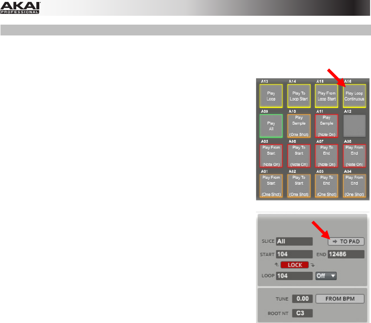
•Slice: Click this drop-down menu to select what part(s) of the sample will
play:
oAll: The entire sample will play.
oPad: The sample will play from the Pad Start position to the Pad End
position, described below. This also lets you activate Pad Loop.
oSlice 1, 2, 3, etc.: If you have sliced the sample in Chop Mode, you
can select which slice will play when you trigger the pad.
•Dir: Click this drop-down menu to select in which direction the sample will
play:
oFwd: The sample will play in the normal forward direction.
oRev: The sample will play in reverse.
•Offset: Click and drag this field up or down to determine a time offset for
the sample's playback. Alternatively, double-click the field and type in a
number.
oPositive values (right of center): When the pad is played, playback
will start immediately but at a later point in the sample specified by
the offset value.
oNegative values (left of center): When the pad is played, playback
will be delayed by the amount specified by the offset value.
309
•Pad Start: Click and drag this field up or down to
determine the position (in samples) where the pad's
playback will start. Alternatively, double-click the
field and type in a number. The minimum value is 0,
and the maximum value is the Pad End value.
•Pad End: Click and drag this field up or down to
determine the position (in samples) where the pad's
playback will stop. Alternatively, double-click the
field and type in a number. The minimum value is the
Pad Start value, and the maximum value is the
sample's total length (in samples).
•Pad Loop: Click this box to activate or deactivate
Pad Loop. When activated, you can hold down the
pad to cause that sample to repeat from the Loop
Position (Loop Pos) to the end of the sample.
Release the pad to stop the repeating playback.
Important: For Pad Loop to work, you must set
Sample Play (in the Pad Play Modes section) to
Note On instead of One Shot.
•Loop Pos (position): Click and drag this field up or
down to determine the position (in samples) where
the pad's playback will repeat when Pad Loop is
activated. Alternatively, double-click the field and
type in a number.
310
Hardware: There are several new settings in the Samples tab that affect how the sample plays when
you trigger its pad.
To edit the new Samples settings:
1.Press Prog Edit to enter Program Edit Mode.
2.Press F2 (Samples) to select the Samples tab.
•Press F2 to cycle through the available four pages of the tab.
•Use the Cursor Buttons to select a parameter. Use the Data Dial or –/+ buttons to adjust the
parameter value:
•Slice: This determines what part(s) of the sample will play:
•All: The entire sample will play.
•Pad: The sample will play from the Pad Start position to the Pad End position, described
below. This also lets you activate Pad Loop.
•Slice 1, 2, 3, etc.: If you have sliced the sample in Chop Mode, you can select which slice will
play when you trigger the pad.
•Dir: This determines which direction the sample will play:
•Fwd: The sample will play in the normal forward direction.
•Rev: The sample will play in reverse.
•Offset: This determines a time offset for the sample's playback.
•Positive values: When the pad is played, playback will start immediately but at a later point in
the sample specified by the offset value.
•Negative values: When the pad is played, playback will be delayed by the amount specified by
the offset value.
The second Samples tab in Program Edit Mode in the MPC hardware display.
311
•Pad Start: This determines the position (in samples) where the pad's playback will start. The
minimum value is 0, and the maximum value is the Pad End value.
•Pad End: This determines the position (in samples) where the pad's playback will stop. The
minimum value is the Pad Start value, and the maximum value is the sample's total length (in
samples).
The third Samples tab in Program Edit Mode in the MPC hardware display.
•Pad Loop: This activates or deactivates Pad Loop. When On, you can hold down the pad to
cause that sample to repeat from the Loop Position (Loop Pos) to the end of the sample. Release
the pad to stop the repeating playback. This option is disabled (–) if Slice is not set to Pad.
•For Pad Loop to work, you must set the Sample field (in the Lfo Mod tab (F5)) to NoteOn instead
of OneSht (One Shot).
•Pad Loop Pos: Click and drag this field up or down to determine the position (in samples) where
the pad's playback will repeat when Pad Loop is activated.
The fourth Samples tab in Program Edit Mode in the MPC hardware display.
312
Sample Record Mode
General
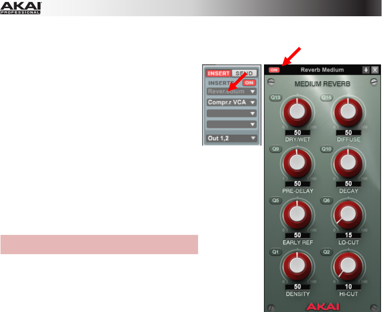
Input insert effects now allow you to apply effects to incoming audio. You can do this
while recording samples and while recording with the looper.
You can also choose to record samples as mono audio or stereo audio. To select mono
or stereo recording, click the
(mono) or (stereo) button under the insert effect
slots.
Tip: Use this to send a mono audio source through a stereo plugin as a mono signal,
and then record the plugin's output as a stereo signal.
Looper
Sample Record Mode now has a built-in looper, letting you record and overdub in real time. You can
also export the loop as a sample for use in your project.
313
To switch between the looper and the normal sampler,
click Looper or Sampler above the Q-Link Knobs.
Hardware: To switch between the looper and the normal
sampler, press F1 (Sampler or Looper).
To set the length of your loop, click and drag the Num Bars
field up or down.
Hardware: To set the length of your loop, use the Cursor
Buttons to select the Bars field, and use the Data Dial or –/+
buttons to adjust the value. Alternatively, use the numeric
keypad to enter a value.
The Looper tab in Sample Record Mode in the MPC hardware display.
314
To set the loop recording behavior, click the Rec Loop drop-down
menu and select Play or Overdub.
•Play: When you start recording a loop, the looper will record the
incoming audio signal during the first time through the loop. After
that (when the loop repeats), the loop will play back without
recording.
•Overdub: When you start recording a loop, the looper will record the incoming audio signal every
time the loop plays, including when the loop repeats, overdubbing it onto the existing loop.
Hardware: To set the length of your loop, use the Cursor Buttons to select the Rec To field, and use
the Data Dial or –/+ buttons to select Play or Over:
•Play: When you start recording a loop, the looper will record the incoming audio signal during the
first time through the loop. After that (when the loop repeats), the loop will play back without
recording.
•Over: When you start recording a loop, the looper will record the incoming audio signal every time
the loop plays, including when the loop repeats, overdubbing it onto the existing loop.
To sync or unsync the looper with Sequence playback, click Seq Sync. When Seq Sync is on, the
looper will stay in step with your current Sequence. When you play or record into the looper, it will wait
until the Sequence starts playing Bar 1 again to start.
Hardware: To sync or unsync the looper with Sequence playback, use the Cursor Buttons to select the
Sync field, and use the Data Dial or –/+ buttons to select On or Off. When Sync is on, the looper will
stay in step with your current Sequence. When you play or record into the looper, it will wait until the
Sequence starts playing Bar 1 again to start.
The Looper tab in Sample Record Mode in the MPC hardware display.
315
To start recording a loop:
•If SeqSync is on, click Record in the Looper section to record-
arm the looper. To start recording, click the software transport
section's Play button. To erase the recording, click Clear.
•If SeqSync is off, click Record in the Looper section.
Recording will start immediately.
Important: When +Overdub is on, the looper will record without erasing any audio you've already
recorded in the loop. When Replace is on, the looper will record and overwrite any audio you've
already recorded in the loop.
Hardware: To start recording a loop:
•If Sync is On, press F6 (Record) to record-arm the looper. To start recording, press the Play button
on your hardware's transport control. To erase the recording, press and hold Shift and press F6
(Clear).
•If Sync is Off, press F6 (Record). Recording will start immediately.
Important: When Overdub is on, the looper will record without erasing any audio you've already
recorded in the loop. When Replace is on, the looper will record and overwrite any audio you've already
recorded in the loop.
The Looper tab in Sample Record Mode in the MPC hardware display.
Hardware Tip: Use a footswitch with MPC Renaissance to speed up your looper workflow: Connect a
footswitch (sold separately) to MPC Renaissance's Footswitch 1 or Footswitch 2 input, and then set
that footswitch to send the desired transport command in the Preferences.
316
To play or stop the loop, click Play in the Looper section.
Hardware: To play or stop the loop, press F4 (Play).
To reverse loop playback, click
Reverse in the Looper section. If Seq
Sync is on, playback will reverse once the looper's playhead reaches the
end of the loop. If Seq Sync is off, playback will reverse immediately.
Hardware: To reverse loop playback, press F3 (Reverse). If Seq Sync is
on, playback will reverse once the looper's playhead reaches the end of
the loop. If Seq Sync is off, playback will reverse immediately.
To erase the loop, click Clear in the Looper section. The loop will be erased immediately.
Hardware: To erase the loop, press and hold Shift, and then press F6 (Clear). The loop will be erased
immediately.
To export the loop as a sample:
1.Click Export in the Looper section to open the Export
Loop as a Sample window.
2.Click the New Name field and enter a name for the
sample.
3.Optional: Click the Program drop-down menu and
select a Program to assign it to. To ignore this feature,
select <none>.
4.Optional: If you're assigning the sample to a Program, click and drag the Assign to Pad field up or
down to select the desired pad. To ignore this feature, select Off.
5.Click and drag the Root Note field up or down to select the sample's root note.
6.Optional: Click and hold Play to play the sample.
7.Click Do It to confirm your choice or Cancel to cancel.
When your loop is done exporting, it will appear under Project Information with the name you
entered and will be assigned to the Program and pad you selected (if any).
317
Sample Edit Mode
General
The sample timeline above the sample waveform now lets you select
whether it is shown in Beats (which displays as bars.beats.ticks) as well
as the previously available Time (which displays as seconds:milliseconds)
or Samples. To set this, click the left-most part of the timeline or right-click
any other place of the timeline.
When you enter Sample Edit Mode, the sample currently selected in Project Information will
automatically appear in the sample waveform for editing.
When you press a pad in Main Mode, the sample assigned to Layer 1 will be selected in Project
Information.
Hardware Tip: To quickly prepare a sample to edit, press its assigned pad (if it's assigned to the pad's
Layer 1) and then press Sample Edit to enter Sample Edit Mode.
Hardware: When adjusting the start point, end point, or loop point of a sample or slice, turning the Data
Dial to change the value is now scaled based on the zoom level. Zoom in for very fine sample-level
control or zoom out for coarser adjustments.
318
The Sample Process section has been reorganized.
Trim Mode
You can now audition the sample (as it has been edited) using one
of two modes:
•One Shot: Click Pad 10 to start playback and press it again to
stop.
•Note On: Click and hold Pad 11 to start playback and release
it to stop.
Hardware: You can now audition the entire sample using one of
two modes:
•One Shot: Press Pad 10 to start playback. and press it again to
stop.
•Note On: Press and hold Pad 11 to start playback and release
it to stop.
319
You can now retune a sample to the tempo of its current sequence.
To tune a sample to that of its current sequence:
1.Click Sample Edit to enter Sample Edit Mode.
2.Click From BPM in the Process section to open the Calculate
BPM window.
3.Click and drag the Number Of Beats field up or down to
match the number of beats in the desired Sequence.
Alternatively, double-click the field and type in a number.
4.Click Match. The Tempo field will adjust to match that your
current Sequence's tempo, and the Tune field will adjust
automatically. The sample is now tuned to the current Sequence.
5.Click Close to exit the window.
Hardware: To tune a sample to that of its current sequence:
1.In Trim Mode, use the Cursor Buttons to select Tune.
2.Press Window to open the Calculate BPM window.
3.Use the Cursor Buttons to select the Number Of Beats field and use the Data Dial or –/+ buttons
to adjust the value to match the number of beats in the desired Sequence. Alternatively, use the
numeric keypad to enter a value.
4.Press F3 (Match). The Tempo field will adjust to match that your current Sequence's tempo, and the
Tune field will adjust automatically. The sample is now tuned to the current Sequence.
5.Click F4 (Close) to exit the window.
The Calculate BPM window in Sample Edit Mode in the MPC hardware display.
320
You can now use Trim Mode for a specific slice of the sample, previously created and selected in Chop
Mode. This allows for a more detailed view of a single slice than in Chop Mode and gives you more
options for auditioning the slice. You can easily switch between Trim Mode and Chop Mode while doing
this.
To use Trim Mode to edit a slice of a sample:
1.Click Chop to enter Chop Mode.
2.Click the Chop To drop-down menu to select how the sample is sliced. Set the other fields below it
as desired.
3.In the sample waveform above, click the desired slice.
4.Click Trim to enter Trim Mode. The region you are now editing is indicated by the normal start point
and end point markers rather than slice markers.
5.Click Chop at any time to return to Chop Mode.
Hardware: To use Trim Mode to edit a slice of a sample:
1.If the tab above F1 says Trim, press it so it says Chop.
2.Use the Cursor Buttons to select the Chop To field and use the Data Dial or –/+ buttons to select
how the sample is sliced. Set the other fields next to it as desired.
3.Use the Cursor Buttons to select the Slice field and use the Data Dial or –/+ buttons to select the
desired slice. Alternatively, use the numeric keypad to enter a value.
4.Press F1 (Chop) to enter Trim Mode. The region you are now editing is indicated by the normal start
point and end point markers rather than slice markers.
5.Press F1 (Trim) to at any time to return to Chop Mode.
321
The Time Stretch process now has a Ratio setting, letting you easily calculate the time stretch factor.
To use the Ratio setting:
1.Click Time Stretch to open the Process Sample window.
2.Click and drag the Number Of Beats field up or down to
the desired value. Alternatively, double-click the field and
type in a number.
3.Click and drag the New field up or down to the desired
new tempo. Alternatively, double-click the field and type in
a number. The Ratio field will change automatically to
indicate the time stretch factor.
To adjust the ratio instead, click and drag the Ratio field up or down to the desired ratio.
Alternatively, double-click the field and type in a number. The New field will change automatically
based on the new time stretch factor.
Hardware: The Time Stretch process now has a Ratio setting, letting you easily calculate the time
stretch factor.
To use the Ratio setting:
1.In Trim Mode, press F6 (Process) to open the Process Sample window.
2.Use the Data Dial or –/+ buttons to set the Function field to Time Stretch.
3.Use the Cursor Buttons to select the New field and use the Data Dial or –/+ buttons to set the
desired value. Alternatively, use the numeric keypad to enter a value. The Ratio field will change
automatically to indicate the time stretch factor.
•To adjust the ratio instead, use the Cursor Buttons to select the Ratio field and use the Data Dial or
–/+ buttons to set the desired value. Alternatively, use the numeric keypad to enter a value. The
New field will change automatically based on the new time stretch factor.
4.Click F5 (Do It) or F4 (Cancel) to confirm or cancel the operation and exit the window.
Time Stretch in the Process Sample window in the MPC hardware display.
322
Chop Mode
Chop Mode is now non-destructive: You can choose the slice/edit behavior in Chop Mode (in Sample
Edit Mode) without destroying your original sample, giving you more control over sample playback; you
can save your sliced sample and but also reuse all of the slice data in another project.
See Program Edit Mode > Layer Section of this addendum to learn more about setting a pad to play
the entire sample, a specific slice of a sample, or a specific region of the sample (independent of its slice
markers).
The slice markers above the sample waveform
now show their slice numbers and are clearer and
easier to move. Red slice markers indicate the
slice you are editing using the hardware. Green
slice markers are used for all other slices.
Also, slice markers are now "adaptively"
displayed: The end marker is shown only for the
currently selected slice.
Furthermore, slices no longer have to be
sequential or contiguous. They can even overlap.
Important:Link Slices must be deactivated to
make slices nonsequential, noncontiguous, or
overlapping.
Hardware: When selecting the slicing mode (Threshold, Regions, or BPM), the display will now show
these options in a new screen where you can cancel or confirm your selection. This prevents any
accidental deletion or shifting of your slice markers.
To select the slice mode:
1.Use the Cursor Buttons to select the Chop To field.
2.Press Window or use the Data Dial or –/+ buttons to open the Chop Mode window.
3.Use the Data Dial or –/+ buttons to select the desired slicing mode.
4.Press F5 (Do It) to confirm your choice or F4 (Close) to cancel.
323
Some features have remained the same but have been reorganized or are accessible in multiple places:
•Settings Section: This section is no longer uses that name as it contains many other functions
including slice conversion and assignment.
•Select Slice: This feature is now assigned to Q-Link KnobQ16 rather than Q15.
•Zero Snap (previously Snap to Zero): This button is now above the Q-Link Knobs rather than in the
Settings Section.
•Link Slices: This button is now above the Q-Link Knobs rather than in the Settings Section.
•Audition and One Shot / Note On: The earlier Audition feature, which assigned each slice to a
pad, is now always activated. The One Shot / Note On menu, which determines how the pads play
their slices, is now labeled Pad Audition.
There is now a cue playhead, which is useful when manually inserting slice
markers. You can set its position and behavior to suit your workflow. To quickly
place it, click the desired location in the grey timeline. You can also click and
drag it to adjust it further.
To use the cue playhead:
1.Click the desired location in the grey timeline to quickly place it at that point
in the sample waveform. You can also click and drag it to adjust it further.
The Cue field will show the current position (in samples). Alternatively,
double-click the Cue field and type in the desired position (in samples).
2.Click the Cue Audition drop-down menu and select one of the following:
•One Shot: Clicking Cue Play (Play) will play the entire sample from the
cue playhead.
•Toggle: Clicking Cue Play (Play) once will start playback from cue
playhead. Clicking it once more will stop playback.
Note: The Pad Audition button is the same as the Audition button in earlier
MPC releases' Settings Section.
3.Click Cue Play (Play) to play the sample from the cue playhead.
4.If you want to set a slice marker at that position, click +Slice.
If you want to adjust the slice marker further, repeat Steps 1 and 3 as desired.
324
To set what audio (if any) plays while you
move the cue playhead or a slice marker:
Click the Edit menu, select Preferences,
and click the Other tab. Click each of
these drop-down menus to set them,
then click OK.
•Cue Preview: This is useful for
precise placement of the cue
playhead. As you move the cue
playhead through the sample
waveform, you can set it to play the
small part of the sample Before the
cue playhead, play the small part of
the sample After the cue playhead,
or not play at all (Off).
•Slice Preview: This is useful for
precise placement of a slice marker.
As you move the slice marker
through the sample waveform, you
can set it to play the small part of
the sample Before the slice marker,
play the small part of the sample
After the slice marker, or not play at
all (Off).
325
Hardware: There is now a cue playhead, which is useful when manually inserting slice markers. You can
set its position and behavior to suit your workflow.
To use the cue playhead:
1.Turn Q-Link Knob Q15 to move the white cue playhead to the desired position in the sample
waveform. (By default, it is at the very start of the sample). The Cue field will show the current
position (in samples). Alternatively, use the Cursor Buttons to select the Cue field and turn the Data
Dial or –/+ buttons, or type in a value using the numeric keypad.
The cue playhead (the dotted vertical line in Slice 4/8) The Cue Play Mode window in Chop Mode
in Chop Mode in the MPC hardware display. in the MPC hardware display.
2.Use the Cursor Buttons to select the Start, End, or Cue field.
3.Press Window to open the Cue Play Mode window.
4.Use the Cursor Buttons to select a field and use the Data Dial or –/+ buttons to select the setting:
•Cue Play Mode:
•One Shot: Pressing F5 (Play Cue) will play the entire sample from the cue playhead.
•Toggle: Pressing F5 (Play Cue) once will start playback from cue playhead. Pressing it once
more will stop playback.
•Cue Preview: This is useful for precise placement of the cue playhead. As you move the cue
playhead through the sample waveform, you can set it to play the small part of the sample
Before the cue playhead, play the small part of the sample After the cue playhead, or not play at
all (Off).
•Slice Preview: This is useful for precise placement of a slice marker. As you move the slice
marker through the sample waveform, you can set it to play the small part of the sample Before
the slice marker, play the small part of the sample After the slice marker, or not play at all (Off).
5.Press F4 (Close) to close the window.
6.Press F5 (Play Cue) to play the sample from the cue playhead.
7.If you want to set a slice marker at that position, press F6 (Slice +).
326
You can now add slice markers to a sample as it plays, letting you
edit easily in real time. To do this, click +Slice at any point during
sample playback.
Hardware: You can now add slice markers to a sample as it plays,
letting you edit easily in real time. To do this, press F6 (Slice +) at any
point during sample playback.
You can now quickly split or combine slices.
To split the current slice into two slices, click the + button to the right of the Slice field.
To combine the current slice and the previous one, click the – button to the right of the Slice field.
Hardware: You can now quickly split or combine slices.
To split or combine slices:
1.In Chop Mode, use the Cursor Buttons to select the Slice field.
2.Use the Data Dial or –/+ buttons to select the desired slice.
3.Press Window to open the Split/Combine Region window.
4.Press F4 (Split) to split the current slice into two slices, press F5 (Combine) to combine the current
slice and previous one, or press F2 (Back) to cancel the operation.
The Split/Combine Region window in Sample Edit Mode in the MPC hardware display.
327
You can also remove all slices from a sample. To do this, click –All.
Hardware: You can now remove all slices in a sample. To do this, press and hold Shift and press F5
(Clear All).
The second bank of Chop Mode tabs in Sample Edit Mode in the MPC hardware display.
328
You can now easily convert and assign a slice or sample to a pad or
Program. In earlier releases, you had to click the Convert button in the
Process section. Now, it's conveniently under the other slice and
auditon controls.
Clicking any of these five buttons will open the Convert or Assign
Slices window. After making your selections, click Do It to complete the
process or Close to cancel the operation.
Note: After the window is open, you can still select a new conversion/assignment process by clicking
the Convert To drop-down menu and selecting a different one.
Hardware: You can now easily convert and assign a slice or sample to a pad or Program. In earlier
releases, it was an option in the Process Sample page. Now, it's conveniently accessible as a Function
Button with the other slice and auditon controls.
To access the Convert or Assign Slices window, press Shift + F4 (Convert). After the window is
open, use the Convert To field to select one of the 5 conversion/assignment processes.
Use the Cursor Buttons to navigate through the window.
Use the Data Dial or –/+ buttons to change the current setting or value. For numerical values, you can
also use the numeric keypad to enter a value.
The Convert or Assign Slices window in Sample Edit Mode in the MPC hardware display.
329
Non-Destructive Convert: Slice to Pad
Note: This is same as clicking the Convert To drop-down menu
and selecting Assign Slice to Pad.
This feature will assign the current slice to a pad, similar to
applying the Convert process in v1.7 and selecting Assign Slice.
This option, however, doesn't clutter your Program Information
with lots of sample slices; the pad will simply refer to the slice in
this sample instead of creating a new sample.
•Pad: Click this drop-down menu and select the desired pad.
•Slice Type: Click this drop-down menu to select how the
desired pad's Layer section settings in Program Edit Mode will be set when the slice is assigned to
it (see this addendum's Program Edit Mode > Layer Section to learn more about how these
settings work):
oNon-Destructive Slice: The pad's Slice setting will be set to the slice number.
oPad Parameters: The pad's Slice setting will be set to Pad. The Pad Start and Pad End
parameters will be set to the slice's start point and end point values, and the Loop Pos
parameter will be set to the slice's start point but with Pad Loop deactivated.
•Program: Click this drop-down menu to specify a Program to which you want to add the slice.
Important: Clicking Do It will replace the sample on the first Layer of the pad.
330
Hardware:Assign Slice to Pad will assign the current slice to a pad, similar to applying the Convert
process in v1.7 and selecting Assign Slice. This option, however, doesn't clutter your Projectwith lots of
sample slices; the pad will simply refer to the slice in this sample instead of creating a new sample.
•Convert To: This will be set to Assign Slice to Pad. You can use this field to to select a different
conversion/assignment process.
•Pad: Press the desired pad to select it.
•Slice Type: Use this field to select how the desired pad's Layer section settings in Program Edit
Mode will be set when the slice is assigned to it (see this addendum's Program Edit Mode > Layer
Section to learn more about how these settings work):
•Non-Destructive Slice: The pad's Slice setting will be set to the slice number.
•Pad Parameters: The pad's Slice setting will be set to Pad. The Pad Start and Pad End
parameters will be set to the slice's start point and end point values, and the Loop Pos parameter
will be set to the slice's start point but with Pad Loop deactivated.
•Program: Use this field to specify a Program to which you want to add the slice.
Press F5 (Do It) to confirm your choice or F4 (Cancel) or cancel the operation.
Important: Pressing F5 (Do It) will replace the sample on the first Layer of the pad.
Assign Slice to Pad in the MPC hardware display.
331
Non-Destructive Convert: New Program
Note: This is same as clicking the Convert To drop-down menu
and selecting New Program Using Slices.
This feature will create a new Program and assign the current
sample's slices to its pads. The new Program will be named after
the sample and appended with ch.
This is similar to applying the Convert process in v1.7 and
selecting Sliced Samples with Create New Program checked.
This option, however, doesn't clutter your Program Information
with lots of sample slices; each pad will simply refer to a slice in
this sample instead of creating a new sample.
•Slice Type: Click this drop-down menu to select how each pad's Layer section settings in Program
Edit Mode will be set when the slice is assigned to it (see this addendum's Program Edit Mode >
Layer Section to learn more about how these settings work):
oNon-Destructive Slice: Each pad's Slice setting will be set to the slice number.
oPad Parameters: Each pad's Slice setting will be set to Pad. The Pad Start and Pad End
parameters will be set to the slice's start point and end point values, and the Loop Pos
parameter will be set to the slice's start point but with Pad Loop deactivated.
•Create Events: Check this box to create a new Program in which each slice results in a sample
and is automatically assigned to a pad. Furthermore, it will automatically create a new Track in
which each pad plays its corresponding slice in ascending sequence by pad number.
•Number of Bars (available only if Create Events is checked): Click and drag this field up or down
to set how many bars the slices' events will occupy.
332
Hardware:New Program Using Slices will assign the current slice to a pad, similar to applying the
Convert process in v1.7 and selecting Sliced Samples with Create New Program selected. This option,
however, doesn't clutter your Project with lots of sample slices; each pad will simply refer to the slice in
this sample instead of creating a new sample.
•Convert To: This will be set to New Program Using Slices. You can use this field to to select a
different conversion/assignment process.
•Slice Type: Use this field to select how each pad's Layer section settings in Program Edit Mode will
be set when the slice is assigned to it (see this addendum's Program Edit Mode > Layer Section to
learn more about how these settings work):
•Non-Destructive Slice: Each pad's Slice setting will be set to the slice number.
•Pad Parameters: Each pad's Slice setting will be set to Pad. The Pad Start and Pad End
parameters will be set to the slice's start point and end point values, and the Loop Pos parameter
will be set to the slice's start point but with Pad Loop deactivated.
•Create Events: Set this to On to create a new Program in which each slice results in a sample and is
automatically assigned to a pad. Furthermore, it will automatically create a new Track in which each
pad plays its corresponding slice in ascending sequence by pad number.
•Number of Bars (available only if Create Events is On): This field determines how many bars the
slices' events will occupy.
Press F5 (Do It) to confirm your choice or F4 (Cancel) or cancel the operation.
New Program Using Slices in the MPC hardware display.
333
Extract New Samples: Sample to Pad
Note: This is same as clicking the Convert To drop-down menu
and selecting New Sample to Pad.
This feature will create a new sample from the current one and
assign it to a pad. The new sample will have the same name as the
original one but appended with -# (where # is a consecutive
number).
•Pad: Click this drop-down menu and select the desired pad.
•Crop Sample: Check this box to delete the unused parts
from the sample when it's created and assigned. This feature
is destructive (though the Project will still contain your original
sample).
Leave this box unchecked to keep the unused parts of the sample when it's created and assigned.
This is essentially like editing a sample in Trim Mode and assigning it to a pad, but this method
creates a new sample, so you will still be able to further edit the entire sample even though you are
using only part of it at the moment.
•Program: Click this drop-down menu to specify a Program to which you want to add the sample.
Important: Clicking Do It will replace the sample on the first Layer of the pad.
334
Hardware:New Sample to Pad will create a new sample from the current one and assign it to a pad.
The new sample will have the same name as the original one but appended with -# (where # is a
consecutive number).
•Convert To: This will be set to New Sample to Pad. You can use this field to to select a different
conversion/assignment process.
•Pad: Press the desired pad to select it.
•Crop Sample: Set this to On to delete the unused parts from the sample when it's created and
assigned. This feature is destructive (though the Project will still contain your original sample).
•Set this to Off to keep the unused parts of the sample when it's created and assigned. This is
essentially like editing a sample in Trim Mode and assigning it to a pad, but this method creates a
new sample, so you will still be able to further edit the entire sample even though you are using only
part of it at the moment.
•Program: Use this field to specify a Program to which you want to add the slice.
Press F5 (Do It) to confirm your choice or F4 (Cancel) or cancel the operation.
New Sample to Pad in the MPC hardware display.
335
Extract New Samples: New Program
Note: This is same as clicking the Convert To drop-down menu
and selecting New Program With New Samples.
This feature will create new samples from the current one and
assign them to pads in a new Program. The new Program will be
named after the sample and appended with ch. The new samples
will be appended with SI-# (where # is a consecutive number).
This is similar to applying the Convert process in v1.7 and
selecting Sliced Samples with Create New Program checked.
•Crop Samples: Check this box to delete the unused parts from the samples when they're created
and assigned. This feature is destructive (though the Project will still contain your original sample).
Leave this box unchecked to keep the unused parts of the samples when they're created and
assigned. This is essentially like editing samples in Trim Mode and assigning them to pads, but this
method creates new samples, so you will still be able to further edit the entirety of each sample
even though you are using only part of it at the moment.
•Create New Program: Check this box to create a new Program in which each slice results in a
sample and is automatically assigned to a pad. The new Program will be named after the sample
and appended with ch.
•Create Events (available only if Create New Program is checked): Check this box to create a new
Program in which each slice results in a sample and is automatically assigned to a pad.
Furthermore, it will automatically create a new Track in which each pad plays its corresponding
slice in ascending sequence by pad number.
•Number of Bars (available only if Create Events is checked): Click and drag this field up or down
to set how many bars the slices' events will occupy.
336
Hardware:New Program With New Samples will create new samples from the current one and assign
them to pads in a new Program. The new Program will be named after the sample and appended with
ch. The new samples will be appended with SI-# (where # is a consecutive number). This is similar to
applying the Convert process in v1.7 and selecting Sliced Samples with Create New Program
selected.
•Convert To: This will be set to New Program With New Samples. You can use this field to to select a
different conversion/assignment process.
•Crop Samples: Set this to On to delete the unused parts from the samples when they're created
and assigned. This feature is destructive (though the Project will still contain your original sample).
•Set this to Off to keep the unused parts of the samples when they're created and assigned. This is
essentially like editing samples in Trim Mode and assigning them to pads, but this method creates
new samples, so you will still be able to further edit the entirety of each sample even though you are
using only part of it at the moment.
•Create New Program: Set this to On to create a new Program in which each slice results in a
sample and is automatically assigned to a pad. The new Program will be named after the sample and
appended with ch.
•Create Events (available only if Create New Program is On): Set this to On to create a new
Program in which each slice results in a sample and is automatically assigned to a pad. Furthermore,
it will automatically create a new Track in which each pad plays its corresponding slice in ascending
sequence by pad number.
•Number of Bars (available only if Create Events is On): This field determines how many bars the
slices' events will occupy.
Press F5 (Do It) to confirm your choice or F4 (Cancel) or cancel the operation.
New Program With New Samples in the MPC hardware display.
337
Patched Phrase
Note: This is same as clicking the Convert To drop-down menu and
selecting Patched Phrase.
This is identical to applying the Convert process in v1.7 and
selecting Patched Phrase: It creates a new sample that will play
based on the tempo of your Sequence, and places it in the current
Project. The patched phrase will have the same name as the original
sample but appended with pp and will use a different icon in your
Project Information.
•Number of Bars: Click and drag this field up or down to set how many bars long
the patched phrase is meant to be.
Hardware:Patched Phrase is identical to applying the Convert process in v1.7 and selecting Patched
Phrase: It creates a new sample that will play based on the tempo of your Sequence, and places it in the
current Project. The patched phrase will have the same name as the original sample but appended
with pp.
•Convert To: This will be set to Patched Phrase. You can use this field to to select a different
conversion/assignment process.
•Number of Bars: This field determines how many bars long the patched phrase will be.
Press F5 (Do It) to confirm your choice or F4 (Cancel) or cancel the operation.
Patched Phrase in the MPC hardware display.
338
Program Mode
You can now edit a sample in the context of the Program in which you'll use it. In this mode, you can
adjust the pad parameters as though you were in Program Edit Mode, auditioning and hearing how it will
sound in the Program's audio path.
To do this:
1.In Sample Edit Mode, click the Program Mode button above the Q-Link Knobs. The pads will show
their assigned samples in the current Program.
2.Click a pad to hear its sample(s). The sample on its first layer will automatically appear in the sample
waveform for editing and will be selected in Project Information.
You can still use the Q-Link Knobs as you normally would in Trim Mode.
Hardware: To use Program Mode:
1.In Sample Edit Mode, press F2 (Program).
2.Press a pad to hear its sample(s). The sample on its first layer will automatically appear in the sample
waveform for editing and be selected in the Sample field.
•You can still use the Q-Link Knobs and Function Buttons as you normally would in Trim Mode.
339
Step Sequence Mode
Pad Select
Hardware: You can now use Pad Select to switch to step sequence events on different pads. When
Pad Select is activated, press a pad to select it and hear its sound instead of entering a pad event.
When Pad Select is deactivated, press a pad to enter a step for the current pad, like normal.
To activate or deactivate Pad Select, press F4 (Pad Select).
Pad Select in Step Sequence Mode in the MPC hardware display.
340
Pad Perform Mode
Pad Perform Mode lets you assign musical scales/modes, chords, or progressions to the pads for more
creative performance.
Hardware: To use Pad Perform Mode, press Pad Assign while using a Keygroup Program, MIDI
Program, or Plugin Program. The display will show the current pad bank's mapping of notes or chords.
Use the Cursor Buttons to select a field. Use the Data Dial or –/+ buttons to change the setting/value.
Use the Function Buttons (described below) to access shortcuts to these and other features.
•Type: This determines what will be mapped over the pads:
•Notes: Each pad is assigned a note, ascending by one scale degree with each pad.
•Chords: Each pad is assigned a chord, the root note ascending by one scale degree with each
pad. All available chords will play in the key determined by the Scale.
•Chromatic Chords: Each pad is assigned a chord, the root note ascending by one scale degree
with each pad. You can play any chord type regardless of the key determined by the Scale.
Essentially, this is like the Chords setting but with more options to play chords out of the set key.
•Progressions: Each pad is assigned a chord in a chord progression. You can play the pads in (or
out of) order to construct songs quickly. The available chords are determined by the Chord field.
Playing notes in Pad Perform Mode Playing chords in Pad Perform Mode
in the MPC hardware display. in the MPC hardware display.
Playing chromatic chords in Pad Perform Mode Playing progressions in Pad Perform Mode
in the MPC hardware display. in the MPC hardware display.
341
•Scale: These two fields determine the root note and the scale type.
•Root Note: This is the starting point of the scale. The available notes are all chromatic notes
across the range of the pads. The pad that's assigned the root note will be lit differently (and
highlighted in the display) to indicate where the scale starts in each octave.
•Scale Type: This is the scale or mode based on the root note. (This is disabled when Type is
set to Progressions.) The available scales are:
• Major Gypsy Dorian
• Minor (melodic) Hungarian Gypsy Phrygian
• Pentatonic Major Persian Lydian
• Pentatonic Minor Major Bebop Mixolydian
• Blues (minor) Whole Tone Aeolian
• FlamencoChromatic Locrian
•Chord: This determines what chord type will play when pressing a pad. The resulting chord will use
those scale degrees based off of the pad's root note.
•When the Type is set to Chords, the available chords are:
• 1-3-5 (major/minor) 1-3-5-7 (major7/minor7)
• 1-4-5 (sus4) 1-3-5-7b (dominant)
• 1-2-5 (sus2)
•When the Type is set to Chromatic Chords, the available chords are:
• Major Sus2 Major7 Major9 Augmented
• Minor Sus4 Minor7 Minor9 Diminished
•Banks: This determines how the notes are mapped across the pad banks.
•Start on root ensures that Pad 01 is always the root note of the scale in every pad bank.
•Continuous ensures that Pad 01 of one bank is always one scale degree higher than Pad 16 of
the previous bank.
342
Alternatively, use the Function Buttons to quickly select different Types and Chords:
•F1 (Notes): This automatically sets the Type to Notes.
•F2 (1-3-5): This automatically sets the Type to Chords and sets the Chord to 1-3-5 (major/minor).
•F3 (1-3-5-7): This automatically sets the Type to Chords and sets the Chord to 1-3-5-7
(major7/minor7).
•F4 (Progrsn): This automatically sets the Type to Progressions.
•F5 (Octave –) and F6 (Octave +): This shifts the pad assignments down or up by an octave.
•Shift + F2 (1-4-5): This automatically sets the Type to Chords and sets the Chord to 1-4-5 (sus4).
•Shift + F3 (1-3-5-7b): This automatically sets the Type to Chords and sets the Chord to 1-3-5-7b
(dominant).
•Shift + F5 (Note–) and Shift + F6 (Note+): This shifts the pad assignments down or up by a scale
degree.
First bank of buttons in Pad Perform Mode in the MPC hardware display.
Second bank of buttons in Pad Perform Mode in the MPC hardware display.
343
Effects
Input insert effects allow you to apply effects to incoming audio. You can
do this while recording samples and while recording with the looper.
Vintage Mode effects are now available for all users.
These effects emulate the Vintage Mode of the MPC
Renaissance.
To apply a Vintage Mode effect:
1.When selecting an effect, click the + next to
Vintage Effects.
2.Click the desired Vintage Mode effect.
3.Click Select to confirm your choice or Close to
cancel.
344
Hardware: To apply a Vintage Mode effect:
1.When selecting an effect in the Select Effect window, use the Data Dial or –/+ buttons to move
through the list. The Vintage Mode effects are at the bottom of the list of Akai Professional effects.
2.Press F4 (Select) to confirm your choice or F3 (Back) to cancel.
Vintage Mode effects in the SelectEffect window in the MPC hardware display.
345
Improvements in MPC v1.8
•To open files, you can now drag them from your Explorer (Windows) or Finder (Mac OS X) anywhere
into the MPC software window.
•The file browser will hide the [ProjectData] directories when Project filter (Proj) is activated.
•Windows that open in the software (e.g., Preferences, History, etc.) are now contained in the main
software window rather than spilling outside of it.
•Sample Record Mode now has a larger VU meter for better signal visibility and Threshold control.
•In Sample Edit Mode, the pad colors in Trim Mode and Chop Mode have been updated for easier
viewing.
•Slices created in Chop Mode (in Sample Edit Mode) are now saved into audio file itself; you can drag
that file into a new Project and retain all of the slices from its previous Project.
•Improved audio path performance.
•Various bug fixes and stability enhancements.
Hardware:
•Many minor workflow improvements for MPC Renaissance and MPC Studio users.
•The display shows improved Function Buttons.
•+/–, on/off states, and tab selections are clearer.
•Various bug fixes and stability enhancements.
346
Corrections for the MPC v1.7 User Guide
Keygroup Programs:User Guide 1.7 previously stated that Keygroup Programs have only one channel
strip. This has been corrected in Program Mixer Mode (Page 150).
Keygroup Programs actually have a channel strip for each individual Keygroup (up to 128).
Auto Scroll:User Guide v1.7 previously did not have a description of the Auto Scroll button. This has
been added to General Features > Mode Tab Section (Page 72).
Click the Auto Scroll button to switch between Follow, Page, and Off.
•When set to Follow, depending on the zoom setting, the grid will scroll
along in the background, keeping the position marker centered.
•When set to Page, the grid display will "turn over" to follow the position
marker.
•When set to Off, the grid will not move at all.
These functions also apply to the sample waveform in Sample Edit Mode.
Loading Audio CD Tracks from File Browser:User Guide v1.7 previously did not have a description of
loading tracks from an audio CD. This has been added to General Features > Browsers > File
Browser (Page 65).
To load a track from an audio CD into your Project, click and drag it from the File Browser onto the
software window.
Edit Sequence Window (Hardware):User Guide v1.7 did not have a description of the EditSequence
window (shown in the MPC hardware display only). This has been added to this addendum's Main
Mode > Sequence and Track Editing section.
347
Q-Link (Hardware):User Guide v1.7 did not have a description of the Q-Link window (shown in the
MPC hardware display only).
The explanation of the Q-Link Knob section in the software itself is in Main Mode > Q-Link Section
(Page 113).
Hardware:
1.To open the Q-Link window, press Shift + Prog Edit / Q-Link.
2.Use the Cursor Buttons to select a field. Use the Data Dial or –/+ buttons to change the
setting/value.
3.Use the Cursor Buttons to select the Program field at the top of the window. Use the Data Dial or –
/+ buttons to select the Program whose Q-Link Knobs you want to assign.
4.To start assigning Program parameters to the Q-Link Knobs, press F1 (Prog Q).
•To start assigning effect parameters to the Q-Link Knobs, press F2 (FX Q).
5.To select a Q-Link Knob, use the CursorButtons or simply touch the corresponding Q-Link Knob
on your MPC hardware. (The 16 fields correspond visually to the 16 Q-Link Knobs.)
6.To quickly assign a parameter to the current Q-Link Knob, make sure the Params button is lit (if it
isn't, press F5 (Params)), and then use the Data Dial or –/+ buttons to select a parameter.
The Prog Q tab of the Q-Link window The FX Q tab of the Q-Link window
in the MPC hardware display. in the MPC hardware display.
348
•To edit even more parameters for the current Q-Link Knob, press F4 (Edit). This opens the Program
Q-Link Edit window:
•Program (for Program parameters): Use this field to select the Program whose parameters you
want to assign.
•Effect (for effect parameters): Use this field to select the effect whose parameters you want to
assign. (You have to load an effect before its parameters can be assigned to the Q-Link Knobs.
All effects loaded to the pads or to the Track, independent from their routing, can have their
parameter assigned. See the Effects chapter for more information about loading effects.)
•QLink: Use this field to select the desired Q-Link Knob, or simply touch the corresponding Q-
Link Knob on your MPC hardware.
•Change (for Program parameters): Use this field to select the condition for changing a
parameter. In most cases, you should select Real Time, which changes the sound immediately
when the Q-Link Knob is moved. If Note On is selected, the Q-Link Knob's position will affect the
sound only when its corresponding pad is pressed.
•Pad (for Program parameters): Use this field to select the desired pad you want to control, or
simply press the corresponding pad on your MPC hardware.
•Param: Use this field to select the parameter you want to assign to the Q-Link Knob.
•Touch To: Use this field to select how the Q-Link Knob will respond when you touch it. When
you hold down the Q-Link Trigger button and touch the top of the Q-Link Knob, the assigned
parameter will jump to either its minimum (Min) or maximum (Max) value.
•Press F4 (Close) to return to the main Q-Link window.
7.To set the values of the Q-Link Knobs, make sure the Values button is lit (if it isn't, press F6
(Values)), and then turn the corresponding Q-Link Knobs on your MPC hardware. Alternatively, you
can use the Cursor Buttons to select one and then use Data Dial or –/+ buttons to set a value.
The Program Q-Link Edit window for Program parameters The Program Q-Link Edit window for effect parameters
in the MPC hardware display. in the MPC hardware display.
349
Effects (Hardware):User Guide v1.7 did not have a description of the Effects window (shown in the
MPC hardware display only). The Send and Insert tabs have been moved from F4 and F5 to F1 and F2,
as well.
The explanation of the Effects in the software itself (and corrections due to updates in 1.8) is in Effects >
Send Effects (Page 232) and in Effects > Master Effects (Page 236).
Hardware:
1.To open the Effects window, press Shift + Seq Edit / Effects.
2.To load or adjust send effects, press F1 (Send).
•To load or adjust master insert effects, press F2 (Insert).
3.Use the Cursor Buttons to select the desired effect slot.
4.Use the Data Dial or –/+ buttons to open another page to select an effect. Press F4 (Select) to load
it, or press F3 (Back) to close the page.
5.Send effects only: To set the return level, use the Cursor Buttons to select the desired Level effect
slot. Use the Data Dial or –/+ buttons to set the level.
6.To make further adjustments to the effect parameters, select it, and then press Window to open its
parameter window or F6 (Edit).
The Send tab of the Effects window The Insert tab of the Effects window
in the MPC hardware display. in the MPC hardware display.
Appendix: Effects and Parameters:User Guide v1.7 previously had a few incorrect default parameter
values and Q-Link Knob numbers. These have been corrected in the Appendix > Effects and
Parameters (Page 242).
350
Other (Hardware):User Guide v1.7 did not have a description of the Other window (shown in the MPC
hardware display only).
Hardware:
1.To open the Other window, press Shift + Song / Other.
2.To switch between the Preferences tab and MIDI Control tab, press F1 (Prefs or MidiCtrl).
3.Use the Cursor Buttons to select a field. Use the Data Dial or –/+ buttons to change the
setting/value.
The Preferences tab in the Other window in MPC hardware display.
The Preferences tab shows some of the settings available in the software's Preferences window (in the
Hardware and Other tabs) and other settings not available in the software:
•Auto Button: Use this field to set the Q-Link Trigger button to cycle through automation states for
just for each Program or globally (Global). Learn about automation for Programs in Program Edit
Mode > Master Section. Learn more about global automation in General Features > Mode Tab
Section.
•Number of Taps: Use this field to set how many times you have to press your MPC hardware's Tap
Tempo button until the new tempo is recognized.
•Pad Threshold: Use this field to select a threshold that must be exceeded to trigger the pad.
•Pad Sensitivity: Use this field menu to set how sensitively your MPC hardware's pads respond to
your touch. At lower values, you need to use more force to generate a high-velocity note. At higher
values, it is easier to generate high-velocity notes, even if you do not use much force while pressing
a pad.
•Pad Curve: Use this field to set how your playing is translated into velocity values, starting from A to
D. An A pad curve is essentially linear, while the B, C, and D pad curves are exponential. (See the
diagram in General Features > Software Menus > Edit Menu > Preferences: Hardware Tab.
351
•Footswitch 1 / Footswitch 2: Use these fields to select the functionality of footswitches connected
to your MPC hardware. You can select either transport commands (e.g., Play or Stop) or trigger
commands for pads and the Function Buttons.
•Sampling Bit Depth: Use this field to set the bit depth of the audio recorded from a sample.
•Display Resolution: Use this field to set the resolution of your MPC's hardware display.
•Program Change Target: Use this field to select what an incoming MIDI Program Change message
will change: a Program, Sequence, or Track, or turn this feature Off.
The MIDI Control tab in the Other window in the MPC hardware display.
The MIDI Control tab shows the current control's MIDI settings when your MPC hardware is in MIDI
Control Mode. To select a control, touch, move, or press it, or use the Control field:
•Control: This determines what message the control sends to the software (e.g., acting as a specific
Q-Link Knob, acting as a specific pad, entering a specific mode, revealing or hiding the File Browser,
Undo, Tap Tempo, etc.).
•Light LED: This determines how the control's LED (or multiple LEDs) on the hardware will behave.
•When set to Never, the LED will always be off.
•When set to MIDI Input, the LED will light up when the software receives a MIDI message that
matches that control.
•When set to Local, the LED will light up when you use that control and/or MIDI input is received.
•Midi Channel: This deteremines over which MIDI channel (from 1–16) the control will send MIDI
messages to the software.
•CC Number: (buttons and Q-Link Knobs only): This determines what Control Change the control will
send to the software.
352
•Mode (Q-Link Knobs only): This determines how the Q-Link Knob will control its parameter.
•When set to Absolute, the Q-Link Knob's current position is what determines its parameter's
value; moving the Q-Link Knob may cause its parameter to "snap" to a new position when using
the Q-Link Knob to control different parameters between different modes.
•When set to Relative, moving the Q-Link Knob will adjust its parameter upward or downward
regardless of its position.
•Low Range (Q-Link Knobs only): This is the Q-Link Knob's lowest possible value (0–127).
•High Range (Q-Link Knobs only): This is the Q-Link Knob's highest possible value (0–127).
•Touch Sense (Q-Link Knobs only): This activates or deactivates the Q-Link Knob's touch-capacitive
circuitry.
•When set to On, you can touch the Q-Link Knob to send a Note On message to the software (this
is how your MPC hardware normally works).
•When set to Off, the Q-Link Knob will not send any Note On messages; it will only send CC
messages when you turn it.
•Touch Note (Q-Link Knobs only): This is the MIDI note number the Q-Link Knob will send to the
software when you touch it (0–127 or C-2 to G8). Touch Sense must be On for this to work.
•Type (buttons only): This determines whether the button will behave as a Momentary switch or
Toggle (latching) switch.
•Note (pads only): This is the MIDI note number the pad will send to the software when you press it
(0–127 or C-2 to G8).
•Bank (pads only): This is the pad bank the pad belongs to. If Set All is On, the pad's messages and
parameters will be identical across all eight banks.
•Velocity (pads only): This determines whether the pad will be velocity-sensitive (On) or not (Off).
When set to Off, pressing the pad will send a note at full-level (127) always.
•Aftertouch (pads only): This determines how the pad's aftertouch (pressure applied to the pad after
the initial press) behaves.
•When set to Off, the pad will not send any aftertouch messages.
•When set to Channel, if you press multiple pads that have this setting, the aftertouch messages
they send will be identical.
•When set to Poly, if you press multiple pads, the aftertouch message each pads sends will be
independent from the others'.
•Set All (pads only): When On, the pad's messages and parameters will be identical across all eight
banks.
353
Pad Copy:User Guide v1.7 previously had a description of the Pad Copy button that was obsolete due
to subsequent software improvements. This has been corrected in MPC Hardware Overview >
MPC Renaissance > Top Panel (Page 19) and in MPC Hardware Overview > MPC Studio >
Top Panel (Page 28).
User Guide v1.7 also did not have a description of the Copy Pad window or function as shown in the
MPC hardware display:
The Copy Pad window in the MPC hardware display.
Hardware: To copy one pad (sample and parameters) to another:
1.Press Shift + Pad Assign / Pad Copy to open the Copy Pad window.
2.Use the Cursor Buttons to select the From Pad field. Press the "destination" pad.
3.Use the Cursor Buttons to select the To Pads field. Press select or deselect "destination" pads.
4.Press F5 (Do It) to confirm your choice or F4 (Close) to cancel the operation.
354
Addendum for MPC v1.9
This chapter is an addendum that explains new features and improvements in MPC v1.9. We also
updated certain sections of the earlier pages of the User Guide to correct previous errors.
Some of the most important new features include enhancements in Track Mixer Mode, where you can
now view and use channel strips for returns, submixes, and master outputs.
Track lengths can now be independent of Sequence lengths, which means that you don’t have to copy
and paste content in a Track just so its length matches up with others in the Sequence. For instance, a
2-bar drum pattern on one Track will loop under an 8-bar bass line on another Track.
We’ve added an easy way to assign pad colors in the software and placed other useful Program editing
processes in the Edit Menu, as well. We’ve also added Project Notes where you can quickly write notes
to yourself and save with each Project.
Please see the Table of Contents: Addendum for MPC v1.9 to learn more about the additions and
improvements in the MPC software.
We hope you enjoy these new features!
Akai Professional
355
Table of Contents: Addendum for MPC v1.9
New Features in MPC v1.9..................................................................................................................... 357
General ............................................................................................................................................... 357
Support for MPC Touch ................................................................................................................ 357
Program Edit Processes ................................................................................................................ 357
Swap Pad Contents ....................................................................................................................... 358
Pad Colors ..................................................................................................................................... 359
Gebruikershandleiding.com neemt misbruik van zijn services uitermate serieus. U kunt hieronder aangeven waarom deze vraag ongepast is. Wij controleren de vraag en zonodig wordt deze verwijderd.
Product:
Spelregels forum
Om tot zinvolle vragen te komen hanteren wij de volgende spelregels:
lees eerst de handleiding door;
controleer of uw vraag al eerder door iemand anders is gesteld;
probeer uw vraag zo duidelijk mogelijk te stellen;
heeft u een probleem en al geprobeerd om dit op te lossen, vermeld dit erbij aub;
heeft u een oplossing gekregen van een bezoeker dan horen wij dat graag in dit forum;
wilt u een reactie geven op een vraag of antwoord, gebruik dan niet dit formulier maar klik op de knop 'reageer op deze vraag';
uw vraag wordt direct op de website gezet; vermijd daarom persoonlijke gegevens in te vullen;
Belangrijk! Als er een antwoord wordt gegeven op uw vraag, dan is het voor de gever van het antwoord nuttig om te weten als u er wel (of niet) mee geholpen bent! Wij vragen u dus ook te reageren op een antwoord.
Belangrijk! Antwoorden worden ook per e-mail naar abonnees gestuurd. Laat uw emailadres achter op deze site, zodat u op de hoogte blijft. U krijgt dan ook andere vragen en antwoorden te zien.
Abonneren
Abonneer u voor het ontvangen van emails voor uw Akai MPC Software bij:
nieuwe vragen en antwoorden
nieuwe handleidingen
U ontvangt een email met instructies om u voor één of beide opties in te schrijven.
Ontvang uw handleiding per email
Vul uw emailadres in en ontvang de handleiding van Akai MPC Software in de taal/talen: Engels als bijlage per email.
De handleiding is 20,23 mb groot.
U ontvangt de handleiding per email binnen enkele minuten. Als u geen email heeft ontvangen, dan heeft u waarschijnlijk een verkeerd emailadres ingevuld of is uw mailbox te vol. Daarnaast kan het zijn dat uw internetprovider een maximum heeft aan de grootte per email. Omdat hier een handleiding wordt meegestuurd, kan het voorkomen dat de email groter is dan toegestaan bij uw provider.
Stel vragen via chat aan uw handleiding
Stel uw vraag over deze PDF
Uw handleiding is per email verstuurd. Controleer uw email
Als u niet binnen een kwartier uw email met handleiding ontvangen heeft, kan het zijn dat u een verkeerd emailadres heeft ingevuld of dat uw emailprovider een maximum grootte per email heeft ingesteld die kleiner is dan de grootte van de handleiding.
Er is een email naar u verstuurd om uw inschrijving definitief te maken.
Controleer uw email en volg de aanwijzingen op om uw inschrijving definitief te maken
U heeft geen emailadres opgegeven
Als u de handleiding per email wilt ontvangen, vul dan een geldig emailadres in.
Uw vraag is op deze pagina toegevoegd
Wilt u een email ontvangen bij een antwoord en/of nieuwe vragen? Vul dan hier uw emailadres in.