618059
14
Verklein
Vergroot
Pagina terug
1/112
Pagina verder
ATMOS
ai
DIVE COMPUTER
OWNER'S GUIDE
2
LIMITED TWO-YEAR WARRANTY
For details, refer to the Product Warranty Registration Card provided.
COPYRIGHT NOTICE
This owners guide is copyrighted, all rights are reserved. It may not, in whole or in part, be copied, photocopied,
reproduced, translated, or reduced to any electronic medium or machine readable form without prior consent in writ-
ing from AERIS / 2002 Design.
ATMOS
ai
Owner's Guide, Doc. No. 12-7153
© 2002 Design 2002
San Leandro, Ca. USA 94577
TRADEMARK NOTICE
AERIS, the AERIS logo, ATMOS
ai
, and the ATMOS
ai
logo are all registered and unregistered trademarks of
AERIS. All rights are reserved.
PATENT NOTICE
U.S. Patents have been issued, or applied for, to protect the following design features:
Dive Time Remaining (U.S. Patent no. 4,586,136), Data Sensing and Processing Device (U.S. Patent no.
4,882,678), and Ascent Rate Indicator (U.S. Patent no. 5,156,055). User Setable Display (U.S. Patent no.
5,845,235) is owned by Suunto Oy (Finland).
DECOMPRESSION MODEL
The programs within the ATMOS
ai
simulate the absorption of nitrogen into the body by using a mathematical
model. This model is merely a way to apply a limited set of data to a large range of experiences. The ATMOS
ai
dive computer model is based upon the latest research and experiments in decompression theory. Still, using the
ATMOS
ai
, just as using the U.S. Navy (or other) No Decompression Tables, is no guarantee of avoiding
decompression sickness, i.e. the bends. Every divers physiology is different, and can even vary from day to
day. No machine can predict how your body will react to a particular dive profile.
3
CONTENTS
WARRANTY ................................................................................................................................................................. 2
NOTICES ..................................................................................................................................................................... 2
DECOMPRESSION MODEL ....................................................................................................................................... 2
FEATURES AND DISPLAYS ............................................................................................. 7
CONTROL BUTTONS ................................................................................................................................................. 9
BAR GRAPHS ............................................................................................................................................................. 9
Nitrogen Bar Graph ................................................................................................................................................ 9
Oxygen (O2) Bar Graph ........................................................................................................................................ 10
Variable Ascent Rate Indicator ............................................................................................................................. 10
INFORMATIONAL DISPLAYS ................................................................................................................................... 11
Tank Pressure Display .......................................................................................................................................... 11
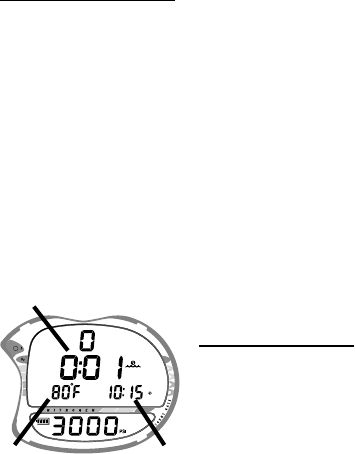
Depth Displays ..................................................................................................................................................... 11
Time and Date Displays ....................................................................................................................................... 12
Temperature Display ............................................................................................................................................. 12
AUDIBLE ALARM ...................................................................................................................................................... 13
LED WARNING INDICATOR ..................................................................................................................................... 14
BACKLIGHT .............................................................................................................................................................. 14
POWER SUPPLY ...................................................................................................................................................... 15
Battery Indicator ................................................................................................................................................... 15
Low Battery Condition .......................................................................................................................................... 15
FO2 MODE ................................................................................................................................................................. 16
FO2 50% Default .................................................................................................................................................. 17
DIVE TIME REMAINING ........................................................................................................................................... 18
ACTIVATION AND SETUP ............................................................................................... 23
ACTIVATION .............................................................................................................................................................. 24
SURFACE MODE ...................................................................................................................................................... 25
SET MODES .............................................................................................................................................................. 26
ENTERING SETTINGS -SET MODE #1 ............................................................................................................... 27
ENTERING SETTINGS -SET MODE #2 ............................................................................................................... 31
4
PRE DIVE PLAN MODE .................................................................................................. 47
DIVE PLANNER ........................................................................................................................................................ 48
DIVE MODES ................................................................................................................... 51
DIVE MODE BAR GRAPHS ...................................................................................................................................... 52
CONTROL OF DISPLAYS ......................................................................................................................................... 52
NO DECOMPRESSION DIVE MODE ....................................................................................................................... 53
DECOMPRESSION DIVE MODE ............................................................................................................................. 56
VIOLATION MODES .................................................................................................................................................. 58
Conditional Violation Mode .................................................................................................................................. 59
Delayed Violation Modes ..................................................................................................................................... 60
Immediate Violation Mode and Violation Gauge Mode ....................................................................................... 62
HIGH PO2 DIVE MODE ............................................................................................................................................. 63
HIGH OXYGEN ACCUMULATION ............................................................................................................................ 65
USER SET DIGITAL GAUGE MODE ........................................................................................................................ 67
POST DIVE MODES ........................................................................................................ 69
POST DIVE SURFACE MODE .................................................................................................................................. 70
TRANSITION PERIOD .............................................................................................................................................. 70
AFTER THE TRANSITION PERIOD (THE FIRST 2 HOURS) .................................................................................. 72
To access the Dive Planner (Plan Mode) ............................................................................................................. 72
To access the Time to Fly Countdown ................................................................................................................. 73
To access the Time to Desaturate Countdown .................................................................................................... 73
LOG MODE .......................................................................................................................................................... 74
AFTER THE FIRST 2 HOURS ................................................................................................................................... 77
DOWNLOADING DATA TO A PC .............................................................................................................................. 78
SIMULATOR (DEMO) MODE .......................................................................................... 79
CONTENTS (continued)
5
CARE, MAINTENANCE, AND SERVICE......................................................................... 87
CARE AND CLEANING ............................................................................................................................................. 88
INSPECTIONS AND SERVICE ................................................................................................................................. 89
BATTERY REPLACEMENT ...................................................................................................................................... 90
REFERENCE ................................................................................................................... 95
DECOMPRESSION MODEL ..................................................................................................................................... 96
TISSUE COMPARTMENT CONTROL ...................................................................................................................... 96
NO DECOMPRESSION LIMITS ................................................................................................................................ 97
OXYGEN EXPOSURE LIMITS ................................................................................................................................. 98
ALTITUDE DIVING .................................................................................................................................................... 99
FLYING AFTER DIVING .......................................................................................................................................... 100
SPECIFICATIONS ......................................................................................................... 102
GLOSSARY ................................................................................................................... 107
INSPECTION / SERVICE RECORD .............................................................................. 109
RESET PROCEDURE .................................................................................................... 111
CONTENTS (continued)
Pay special attention to items marked with this Warning symbol.
6
The ATMOS
ai
is not intended for use by military or commercial divers.
The ATMOS
ai
is intended for use by recreational divers who have successfully completed
a nationally recognized course in scuba diving, and diving with enriched nitrogen-oxygen
(nitrox) mixtures.
 It must not be used by untrained persons who may not have knowledge of the potential
risks and hazards of scuba diving, and diving with nitrox.
 You must obtain scuba certification, and certification in diving with nitrox before using the
ATMOS
ai
, if you have not already done so.
 It should NOT be utilized for any competitive, or repetitive square wave or unplanned de-
compression diving, it is intended solely for recreational use and multilevel diving.
As with all underwater life support equipment, improper use or misuse of this product can
cause serious injury or death.
 Conduct your dives in such a manner so as to insure that you continuously check the
computer's proper function.
 If you do not fully understand how to use this dive computer, or if you have any questions,
you should seek instruction in its use from your authorized AERIS dealer before you utilize
this product.
 Never participate in sharing or swapping of a dive computer. Doing so may result in injury
or death.
If you exceed certain limits, the ATMOS
ai
will not be able to tell you how to get safely back
to the surface. These situations exceed tested limits and can result in loss of some ATMOS
ai
functions for 24 hours after the dive in which a Violation occurred.
The ATMOS
ai
enters Immediate Violation Mode when a situation totally exceeds its capac-
ity to predict an ascent procedure. These dives represent gross excursions into decom-
pression that are beyond the boundaries and spirit of the ATMOS
ai
design. If you are fol-
lowing these dive profiles, AERIS advises you not to use an ATMOS
ai
dive computer.
WARNINGS AND SAFETY RECOMMENDATIONS
7
FEATURES and DISPLAYS
8
WELCOME TO AERIS !
AND
THANK YOU FOR CHOOSING THE ATMOS
ai
!
Your ATMOS
ai
presents the information that you need before, during, and after your air (or nitrox)
dives using a combination of easy to read displays and identification icons. It can also be set to oper-
ate simply as a digital depth gauge/timer.
This instructional guide is intended to help you become familiar with the functions and features avail-
able and show you examples of displays that you could expect to see in the various operational
modes. Ensure that you read through this complete Owner's Guide.
Remember that the rules you learned in your basic scuba certification course(s) still apply to the div-
ing you will do while using a dive computer - some will become even more important. Technology is
no substitute for common sense, and a dive computer only provides the person using it with data, not
the knowledge to use it.
Since the ATMOS
ai can
be used when diving with either Air or Nitrox, the term Breathing Gas is used
in this manual.
Breathing Gas is the gaseous mixture breathed during a dive.
Air is a breathing gas that contains approximately 21% oxygen and 79% nitrogen (nature's com-
mon nitrogen-oxygen mixture).
Nitrox is a nitrogen-oxygen breathing gas that contains a higher fraction of oxygen than air
(>21%).
9
CONTROL BUTTONS
The two Control Buttons allow you to select display options, access specific information when you
want to see it, and activate the Unit and the Backlight.
The Front button is named Advance (Fig. 1a) and the Bottom/Side button Select (Fig. 1b).
BAR GRAPHS
Nitrogen Bar Graph
The Nitrogen Bar Graph (Fig. 1c) represents tissue loading of nitrogen, showing your relative no de-
compression or decompression status. As your depth and elapsed dive time increase, segments will
add to the Graph, and as you ascend to shallower depths, the Bar Graph will begin to recede, indicat-
ing that additional no decompression time is allowed for multilevel diving.
The Nitrogen Bar Graph monitors 12 different nitrogen compart-
ments simultaneously and displays the one that is in control of your
dive. It is divided into a green No Decompression (normal) zone, a
yellow Caution zone (also No Decompression), and a red Decom-
pression (danger) zone.
While you cannot provide a guarantee against the occurrence of de-
compression sickness, you may choose your own personal zone of
caution based upon age, physique, excessive weight, etc., to reduce
the statistical risk.
Fig. 1 - Buttons and NiBG
a
b
c
10
Oxygen Accumulation Bar Graph (O2BG)
The O2 Bar Graph (Fig. 2a) represents oxygen loading, your relative
oxygen tolerance dosage (OTU), showing the maximum of either per
dive accumulated oxygen, or 24 hour period accumulated oxygen.
As your accumulation increases during the dive, segments will add to
the Bar Graph, and as loading decreases, it will begin to recede, indi-
cating that additional exposure is allowed.
NOTE: Displays associated with oxygen and the O2
Bar Graph will only appear if FO2 has been set at a
value other than 'Air' (e.g., a numerical value).
Variable Ascent Rate Indicator (VARI)
The Variable Ascent Rate Indicator (Fig. 2b) provides a visual repre-
sentation of ascent speed (i.e., an ascent speedometer). Green is a
'normal' rate, yellow a 'caution' rate, and red is 'Too Fast'. The seg-
ments of the Variable Ascent Rate Indicator represent 2 sets of
speeds which change at a reference depth of 60 feet (18 meters). Re-
fer to the chart for segment values.
WARNING: At depths greater than 60 feet (18
meters), ascent rates should not exceed 60 feet per
minute (18 mpm). At depths of 60 feet (18 meters)
and shallower, ascent rates should not exceed 30
feet per minute (9 meters per minute).
Fig. 2 - O2BG and VARI
Variable Ascent Rate Indicator
Deeper than 60 feet (18 m)
Segments Ascent Rate =
Displayed FPM MPM
0 0-20 0 - 6
1 21-30 6.5-9
2 31-40 9.5-12
3 41-50 12.5-15
4 51-60 15.5-18
5 >60 >18
60 feet (18 m) & Shallower
Segments Ascent Rate =
Displayed FPM MPM
0 0-10 0 - 3
1 11-15 3.5-4.5
2 16-20 5-6
3 21-25 6.5-7.5
4 26-30 8-9
5 >30 >9
a
b
11
INFORMATIONAL DISPLAYS
Each numeric and graphic display represents a unique piece of information. It is imperative
that you understand the formats, ranges, and values of the information represented to avoid
any possible misunderstanding that could result in error.
Tank Pressure Display
Tank pressure is displayed numerically in the lower window (Fig. 3a). Values of pressure are dis-
played from 0 PSI (BAR) up to 5000 PSI (352 BAR) in increments of 10 PSI (.5 BAR).
Depth Displays
During a dive, the Current Depth display (Fig. 3b), indicates depths from 0 to 330 feet (99.9
meters) in 1 foot (.1 meter) increments. The Maximum Depth reached during that dive will be dis-
played in the upper window (Fig. 3c).
When the unit is set to operate as a Digital Depth Gauge/Timer
(referred to as User Set Gauge Mode), the Depth Display range is
'extended' to 399 feet (120 meters).
At depths greater than 99.9 meters, it will indicate metric values
in increments of 1 meter.
During a Decompression Dive, the required Ceiling Stop Depth is
displayed instead of Max Depth. Max Depth can then be viewed by
pressing the Advance (Front) button.
Fig. 3 - Pressure and Depth
c
a
b
12
Time and Date Displays
Time displays are shown in hour:minute format (i.e., 1:22 represents 1 hour and 22 minutes, not
122 minutes!). The colon that separates hours and minutes blinks once per second when the display
is indicating real time (e.g., Elapsed Dive Time), and is solid (non-blinking) when times are calcu-
lated projections (e.g., Time to Fly).
Due to the importance of the information it presents, the Main Time display is configured with the
largest segments of the LCD in the upper window (Fig. 4a). A second time display is located in the
lower right portion of the window (Fig. 4b). Both displays are identified by a clock icon.
Time of Day can be set for 12 hour format (AM/PM) or 24 hour format.
Date is displayed in the lower screen only to identify dive data while it is viewed in the Log Mode.
When Units of Measure are set for 'Imperial', the Month appears to
the left of Day. When set for Metric, the Month appears to the right
of Day.
Temperature Display
Ambient Temperature is displayed in the upper window (Fig. 4c)
while in the Surface Mode and can be viewed as part of an Alternate
Display when the Advance (Front) button is pressed while in a dive
mode. If the Temperature exceeds a value of '99', 2 dashes ( - - ) will
be displayed on the screen until the unit's temperature decreases to
'99'.
Fig. 4 - Time and Temperature
a
b
c
13
NOTE: The Informational Displays are described in detail as the various oper-
ating modes they appear in are presented throughout this manual.
AUDIBLE ALARM
When warning situations activate the Alarm, the unit will emit a continuous beeping tone for 10 sec-
onds, or until the situation is corrected, or it is acknowledged by pressing the Advance (Front) button
for 2 seconds. If acknowledged by the user and the situation corrected, the Alarm will sound again
upon reentry into the warning situation, or entry into another type of warning situation.
A red LED Warning Light located on the upper left portion of the module is synchronized with the
Audible Alarm and will indicate an Alarm when the unit emits a tone. It will be OFF when the
Alarm is acknowledged, or Set OFF (a user setting).
Warning situations that will sound the Alarm, if it is turned ON (a user setting), include -
Entry into Decompression Mode
PO2 => than the Max PO2 Alarm (a user setting), or => 1.60 ATA.
Descent deeper than the Max Depth Alarm (a user setting).
Nitrogen Bar Graph Alarm (a user setting).
Dive Time Remaining Alarm (a user setting).
Elapsed Dive Time Alarm (a user setting).
O2 Accumulation => allowable per dive limit, or limit for a 24 hour period.
Ascending above a required Decompression stop depth for < 5 min. (Conditional Violation).
Ascent rate exceeds 60 fpm (18 mpm) if > 60 ft (18 m), or 30 fpm (9 mpm) if <= 60 ft (18 m).
Turn Pressure Alarm (a user setting).
End Pressure Alarm (a user setting).
14
During the following situations, the 10 second continuous tone will be followed by a 5 second
steady beep that will not turn off when acknowledged, even if it was user Set OFF -
Ascending above a required Decompression stop depth for more > 5 min. (Delayed Violation).
Decompression requires a ceiling stop depth => 70 FT (18 M).
Being on the surface for 5 minutes after a Conditional Violation (Permanent Violation).
A single short beep (which cannot be disabled) is emitted - after the Diagnostic check, upon auto-
matic return to Surface Mode from Simulator Mode, upon completion of a fast battery change with
calculations/settings saved, and upon change from Delayed to Full Violation after that dive.
BACKLIGHT
To activate the Backlight while in the Surface Mode or during a dive-
press the Select (Bottom) button.
The screens (upper and lower) will be illuminated for button depression time plus 3, 5, or 7 sec-
onds (a user setting). Press and release the button again to activate as desired.
The Backlight does not operate during a Low Battery condition.
NOTE: AERIS recommends that you always carry primary and backup dive
lights when conducting dives that could include low light situations.
14

Hulp nodig? Stel uw vraag in het forum

Spelregels

Misbruik melden

Gebruikershandleiding.com neemt misbruik van zijn services uitermate serieus. U kunt hieronder aangeven waarom deze vraag ongepast is. Wij controleren de vraag en zonodig wordt deze verwijderd.

Product:

Bijvoorbeeld antisemitische inhoud, racistische inhoud, of materiaal dat gewelddadige fysieke handelingen tot gevolg kan hebben.

Bijvoorbeeld een creditcardnummer, een persoonlijk identificatienummer, of een geheim adres. E-mailadressen en volledige namen worden niet als privégegevens beschouwd.

Spelregels forum

Om tot zinvolle vragen te komen hanteren wij de volgende spelregels:

Belangrijk! Als er een antwoord wordt gegeven op uw vraag, dan is het voor de gever van het antwoord nuttig om te weten als u er wel (of niet) mee geholpen bent! Wij vragen u dus ook te reageren op een antwoord.

Belangrijk! Antwoorden worden ook per e-mail naar abonnees gestuurd. Laat uw emailadres achter op deze site, zodat u op de hoogte blijft. U krijgt dan ook andere vragen en antwoorden te zien.

Abonneren

Abonneer u voor het ontvangen van emails voor uw Aeris Atmos ai bij:


U ontvangt een email met instructies om u voor één of beide opties in te schrijven.


Ontvang uw handleiding per email

Vul uw emailadres in en ontvang de handleiding van Aeris Atmos ai in de taal/talen: Engels als bijlage per email.

De handleiding is 1,8 mb groot.


U ontvangt de handleiding per email binnen enkele minuten. Als u geen email heeft ontvangen, dan heeft u waarschijnlijk een verkeerd emailadres ingevuld of is uw mailbox te vol. Daarnaast kan het zijn dat uw internetprovider een maximum heeft aan de grootte per email. Omdat hier een handleiding wordt meegestuurd, kan het voorkomen dat de email groter is dan toegestaan bij uw provider.

Stel vragen via chat aan uw handleiding

Stel uw vraag over deze PDF

Uw handleiding is per email verstuurd. Controleer uw email

Als u niet binnen een kwartier uw email met handleiding ontvangen heeft, kan het zijn dat u een verkeerd emailadres heeft ingevuld of dat uw emailprovider een maximum grootte per email heeft ingesteld die kleiner is dan de grootte van de handleiding.

Er is een email naar u verstuurd om uw inschrijving definitief te maken.

Controleer uw email en volg de aanwijzingen op om uw inschrijving definitief te maken

U heeft geen emailadres opgegeven

Als u de handleiding per email wilt ontvangen, vul dan een geldig emailadres in.

Uw vraag is op deze pagina toegevoegd

Wilt u een email ontvangen bij een antwoord en/of nieuwe vragen? Vul dan hier uw emailadres in.


Info