This user guide contains important installation and
operation information.
Make sure that this user guide is handed over when the
product is given to other persons.
Keep this user guide to consult later.
You will find a list of contents with the corresponding
page numbers in the contents.
Contents
3
Important safety information .......................................................................................................................................... 7
Explanation of symbols .................................................................................................................................................... 7
Intended use .................................................................................................................................................................... 7
General ............................................................................................................................................................................ 7
Power supply ................................................................................................................................................................... 7
Children ............................................................................................................................................................................ 8
EU Directives ................................................................................................................................................................... 8
General ............................................................................................................................................................................ 9
Compatible video walls/decoders .................................................................................................................................... 9
Compatible IP cameras .................................................................................................................................................... 9
Supported camera functions .......................................................................................................................................... 10
External I/O connections and wiring ............................................................................................................................ 12
General .......................................................................................................................................................................... 12
General information ....................................................................................................................................................... 15
Starting the device ......................................................................................................................................................... 15
Switching off the device, locking, rebooting ................................................................................................................... 16
Setting up the system .................................................................................................................................................... 17
System time and date .................................................................................................................................................... 18
Hard disk drive management ......................................................................................................................................... 19
Camera assistant ........................................................................................................................................................... 19
Camera recording .......................................................................................................................................................... 19
Live view ......................................................................................................................................................................... 20
General information on live image ................................................................................................................................. 20
Live image function areas .............................................................................................................................................. 20
Menu bar operation ........................................................................................................................................................ 20
Multiview control ............................................................................................................................................................ 20
Action bar operation ....................................................................................................................................................... 21
PTZ control menu .......................................................................................................................................................... 21
Recording Status ........................................................................................................................................................... 22
Right-click menu ............................................................................................................................................................ 22
General information on playback ................................................................................................................................... 23
Action bar operation ....................................................................................................................................................... 23
Contents
4
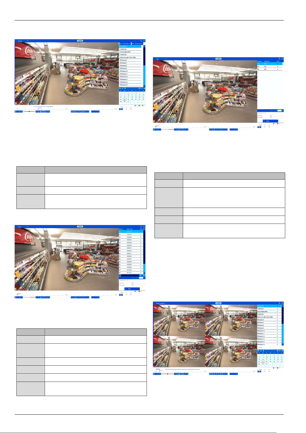
Playback control ............................................................................................................................................................ 23
Audio control .................................................................................................................................................................. 24
Operation time bar and calendar ................................................................................................................................... 25
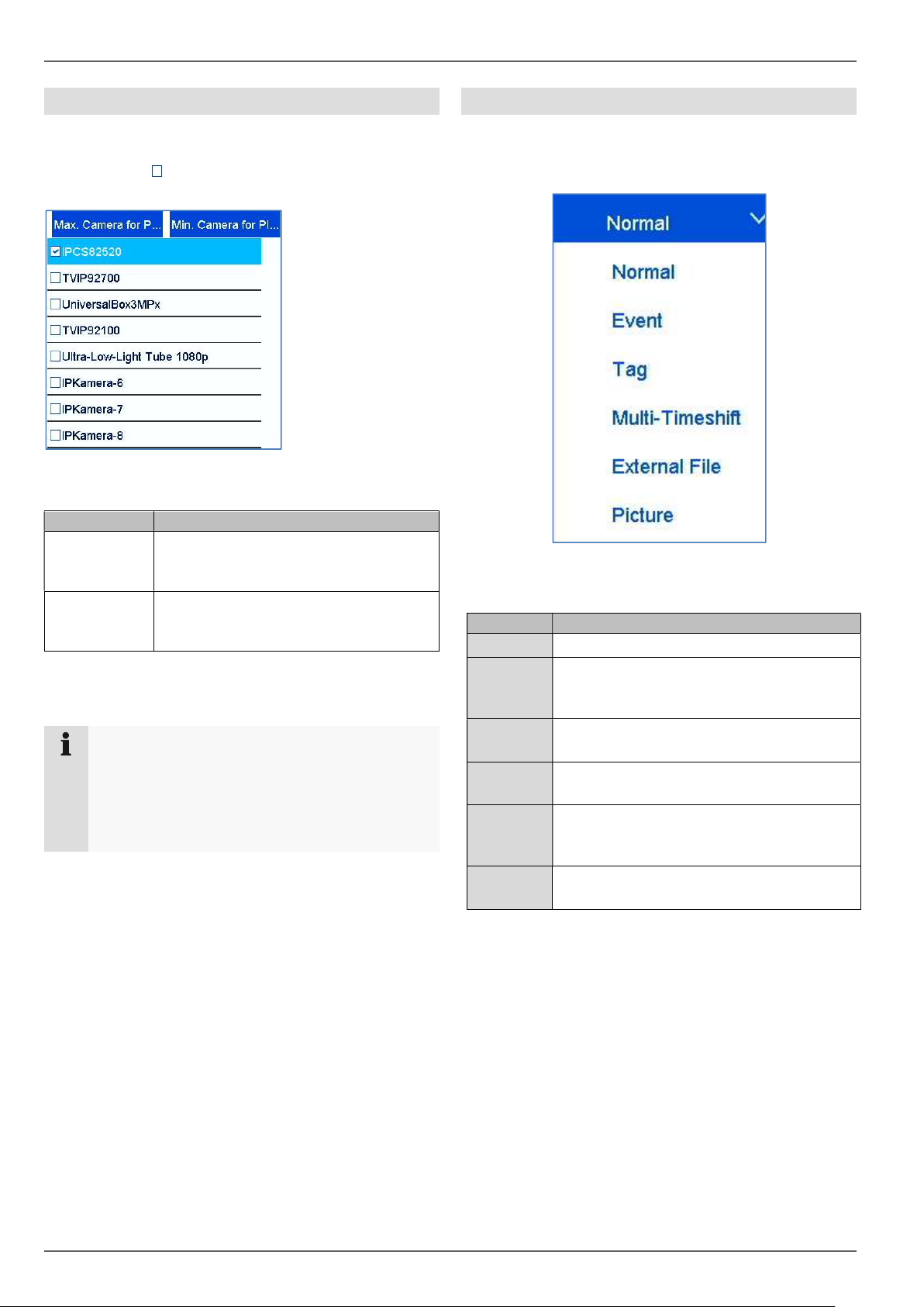
Camera list operation ..................................................................................................................................................... 26
Selecting playback type ................................................................................................................................................. 26
Playback: Normal .......................................................................................................................................................... 27
Playback: Tag ................................................................................................................................................................ 27
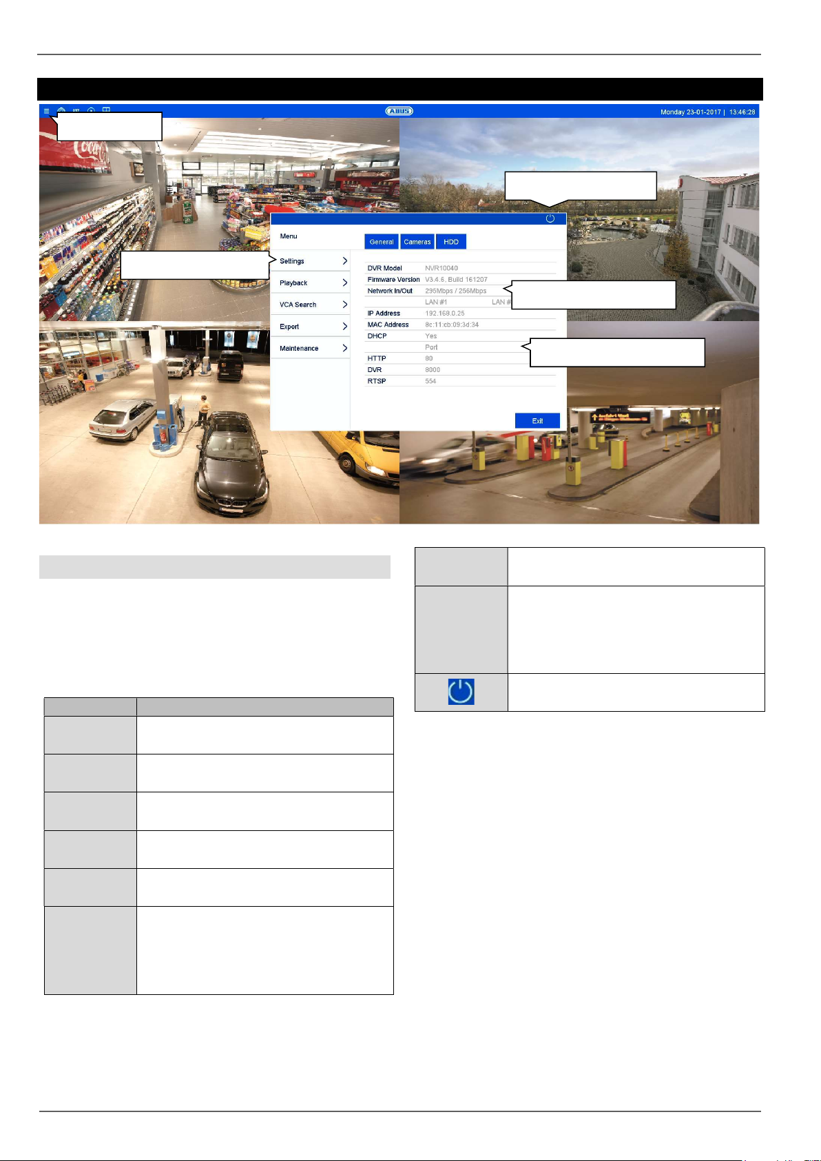
Info menu ........................................................................................................................................................................ 29
General information menu ............................................................................................................................................. 29
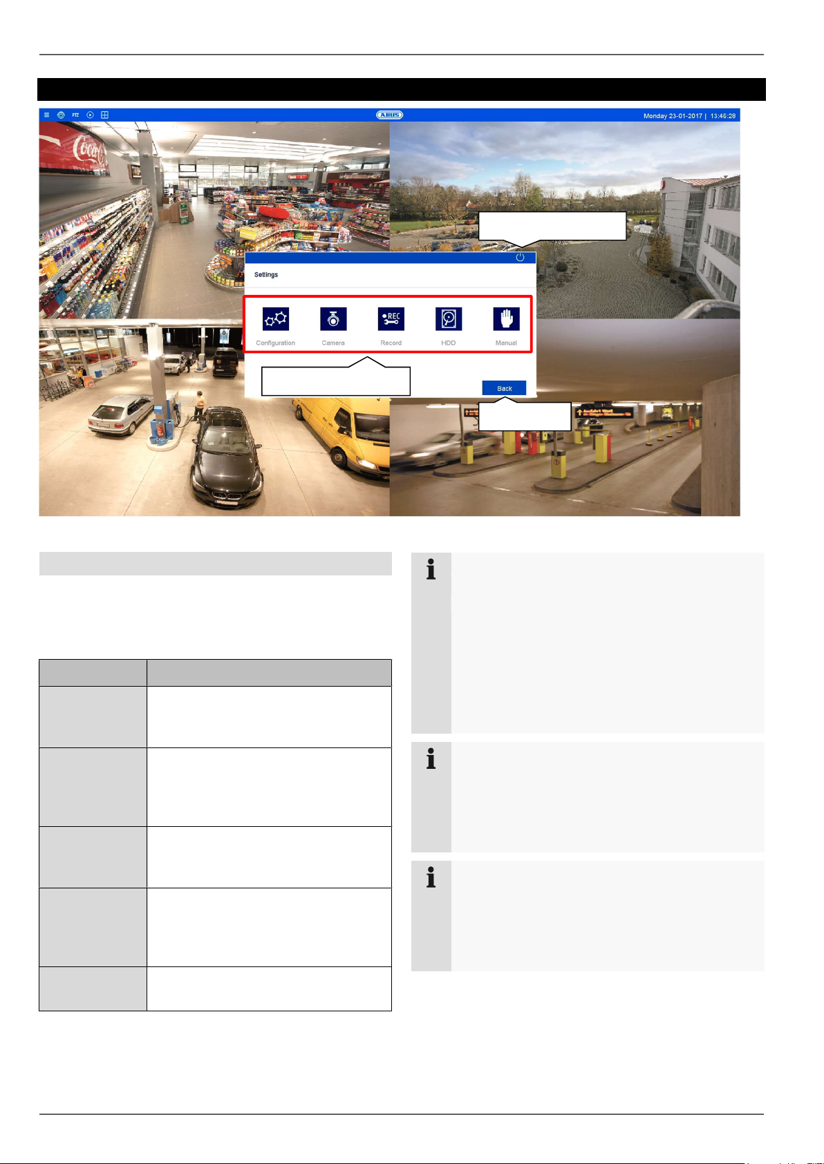
General information on settings ..................................................................................................................................... 30
General information on configuration ............................................................................................................................. 31
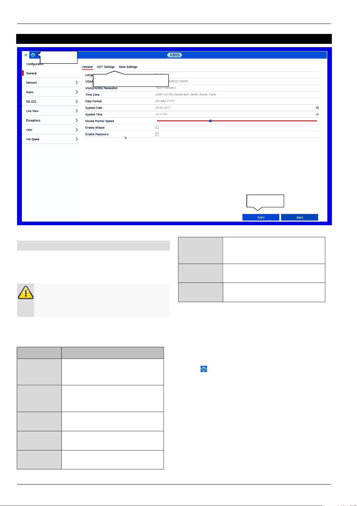
General .......................................................................................................................................................................... 32
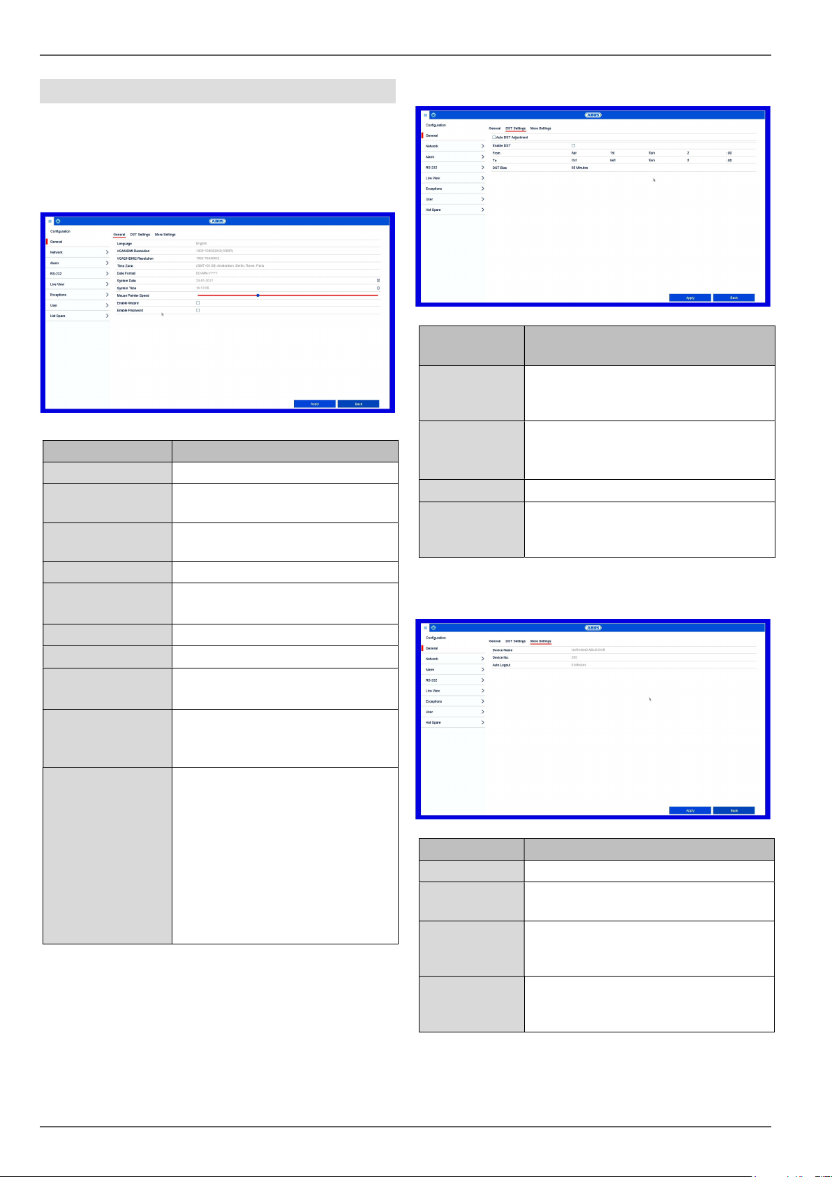
General tab .................................................................................................................................................................... 32
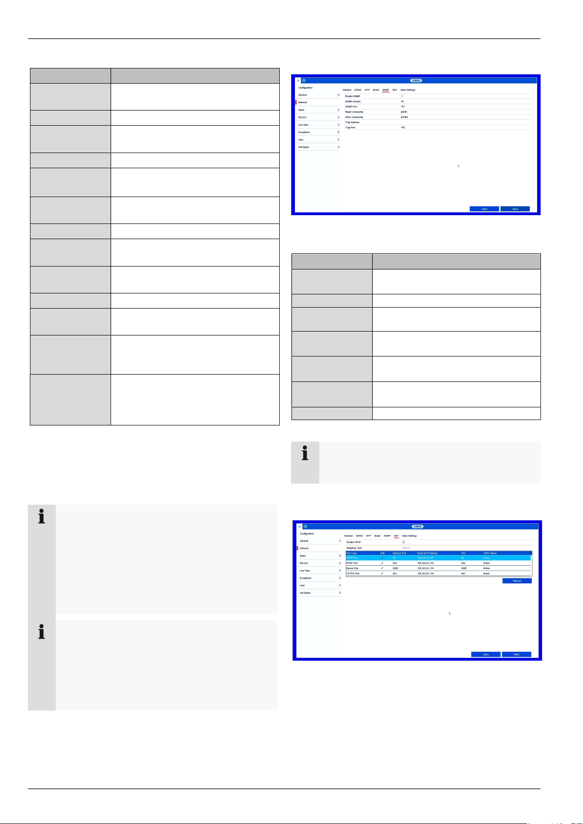
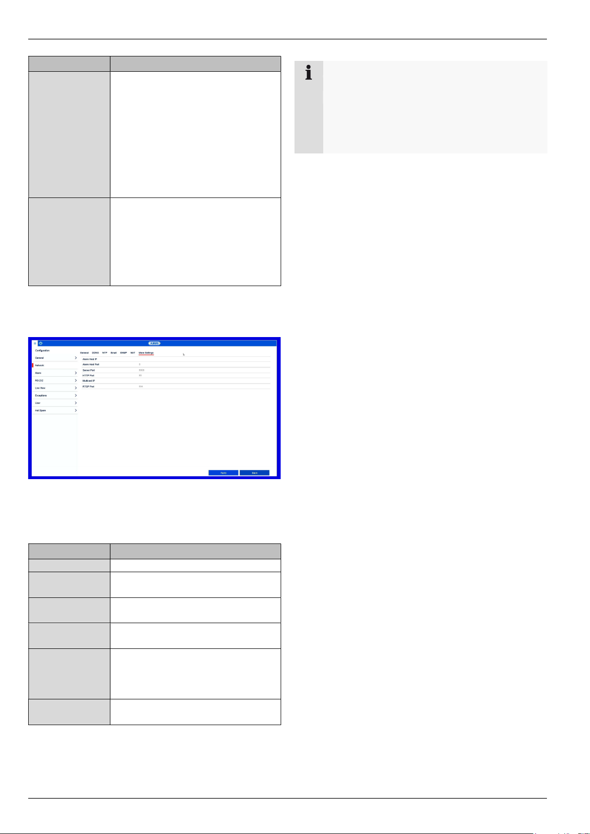
More Settings tab .......................................................................................................................................................... 32
General tab .................................................................................................................................................................... 33
More Settings tab .......................................................................................................................................................... 36
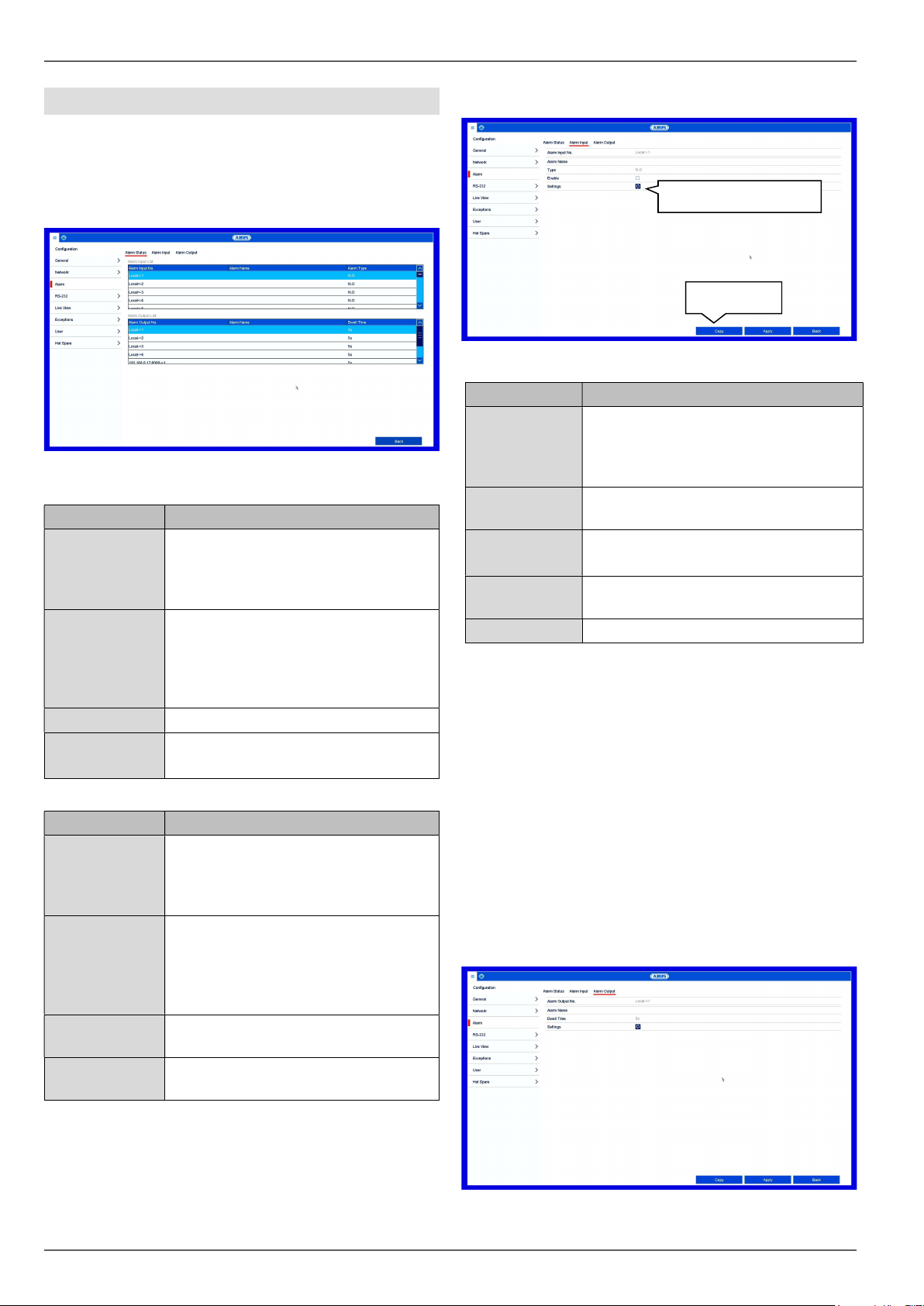
Alarm Status tab ............................................................................................................................................................ 37
Live view ........................................................................................................................................................................ 39
General tab .................................................................................................................................................................... 39
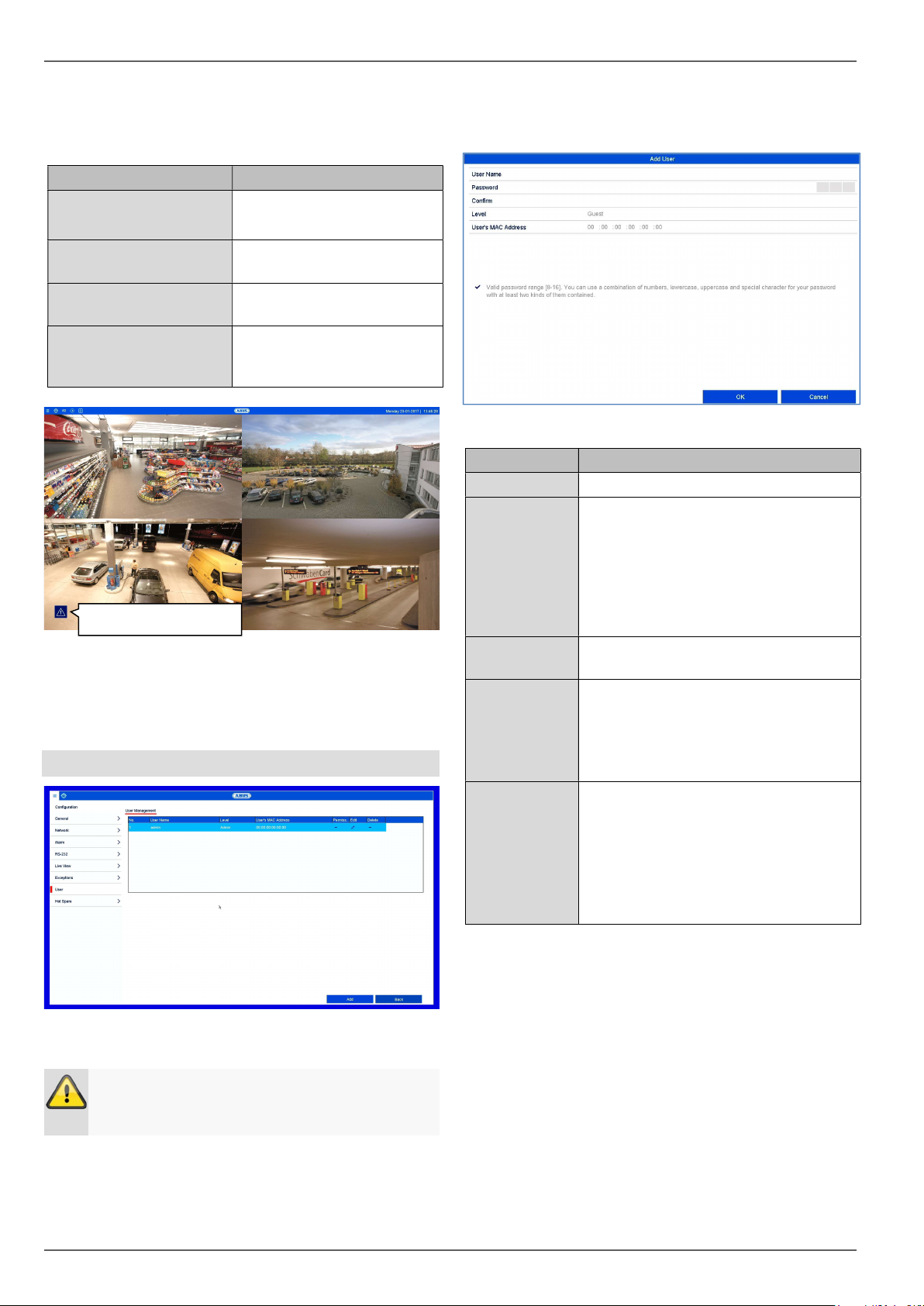
User ................................................................................................................................................................................ 41
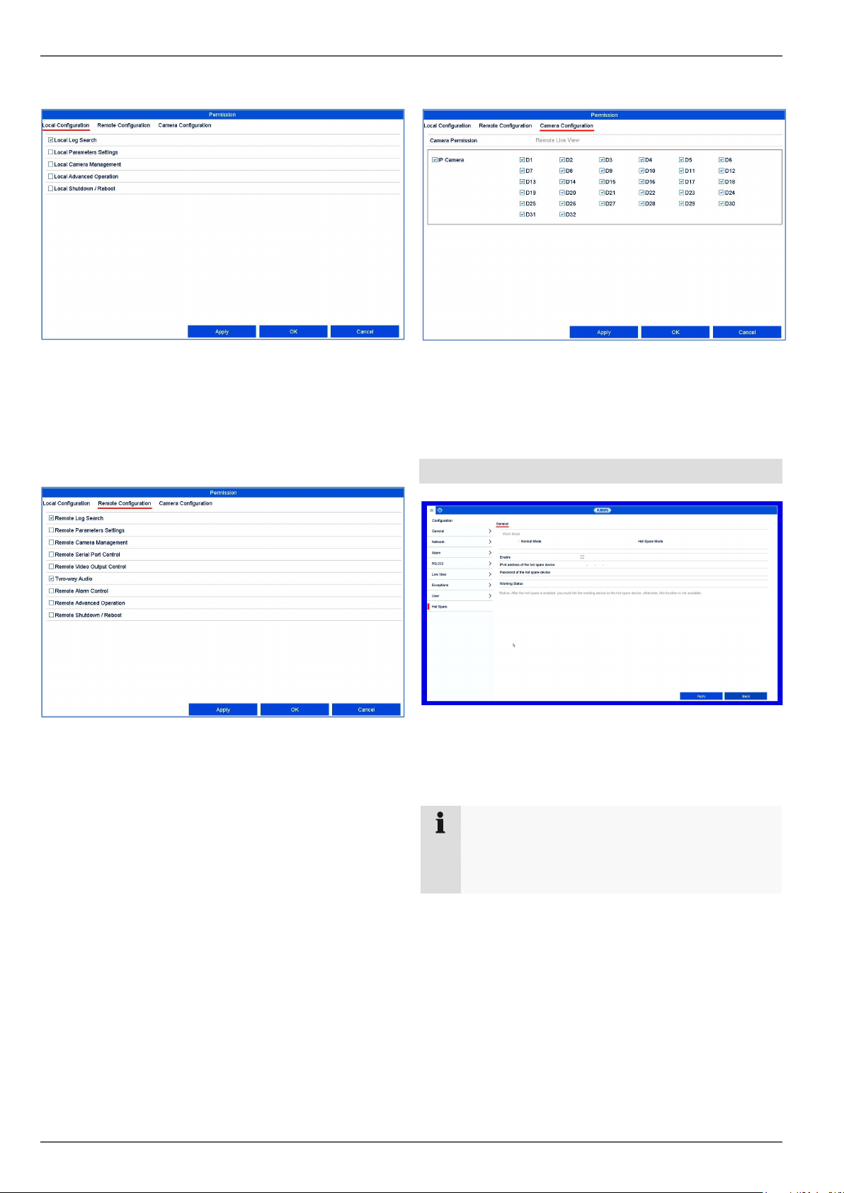
Local configuration tab .................................................................................................................................................. 42
Camera configuration tab .............................................................................................................................................. 42
Hot spare........................................................................................................................................................................ 42
Setting up hot spare mode ............................................................................................................................................ 43
Setting: Camera ............................................................................................................................................................. 44
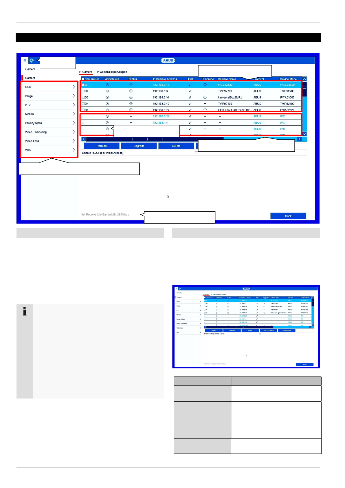
General information on managing cameras................................................................................................................... 44
Contents
5
Camera .......................................................................................................................................................................... 44
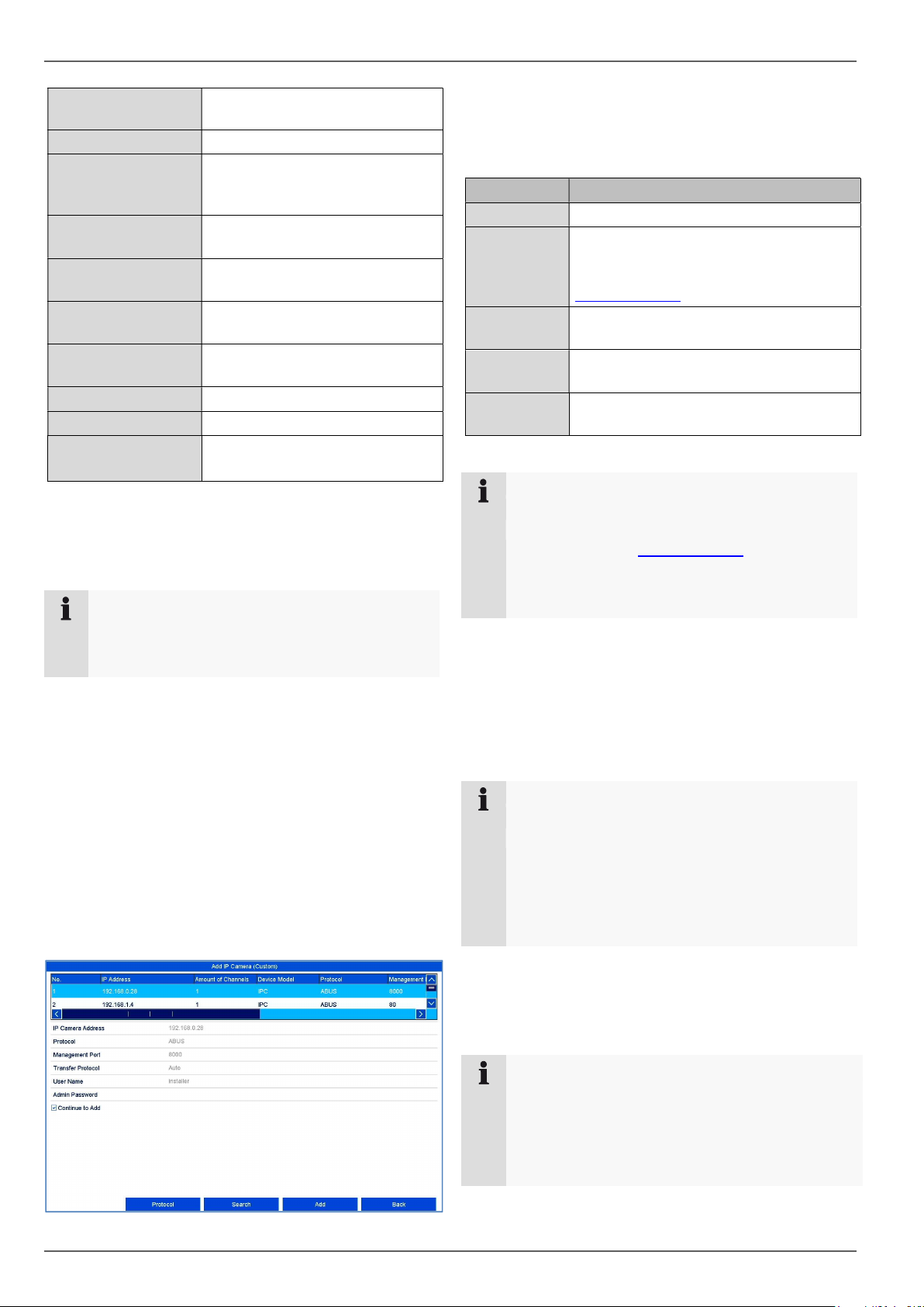
IP Camera tab ............................................................................................................................................................... 44
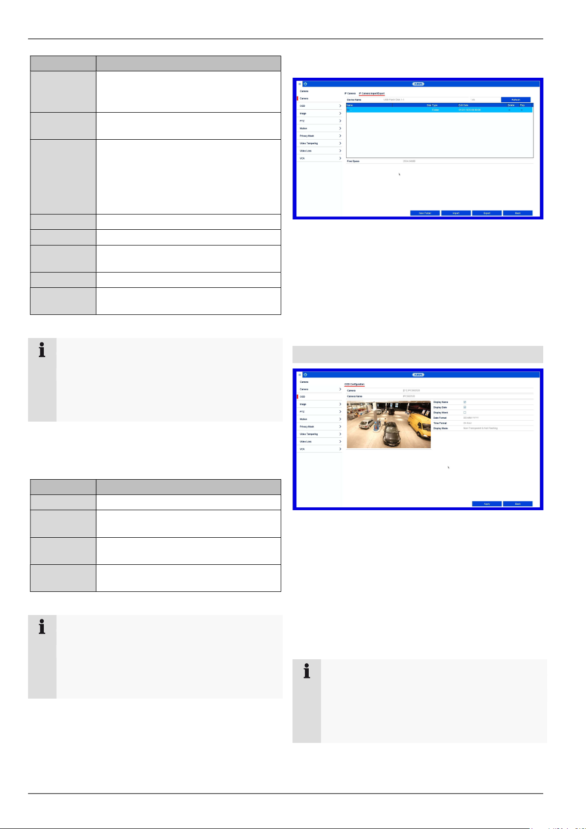
IP camera import/export tab .......................................................................................................................................... 46
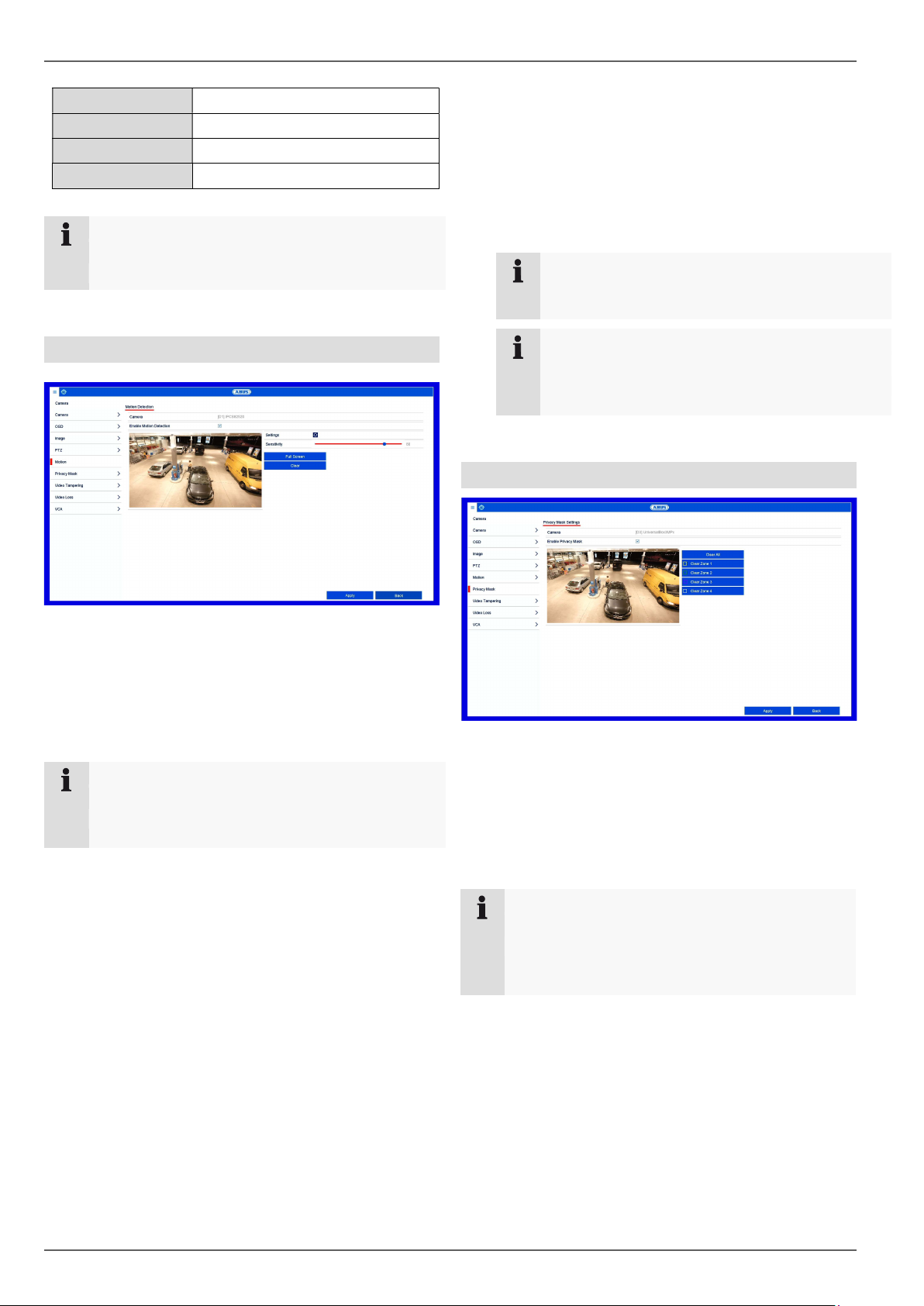
Private Zone ................................................................................................................................................................... 48
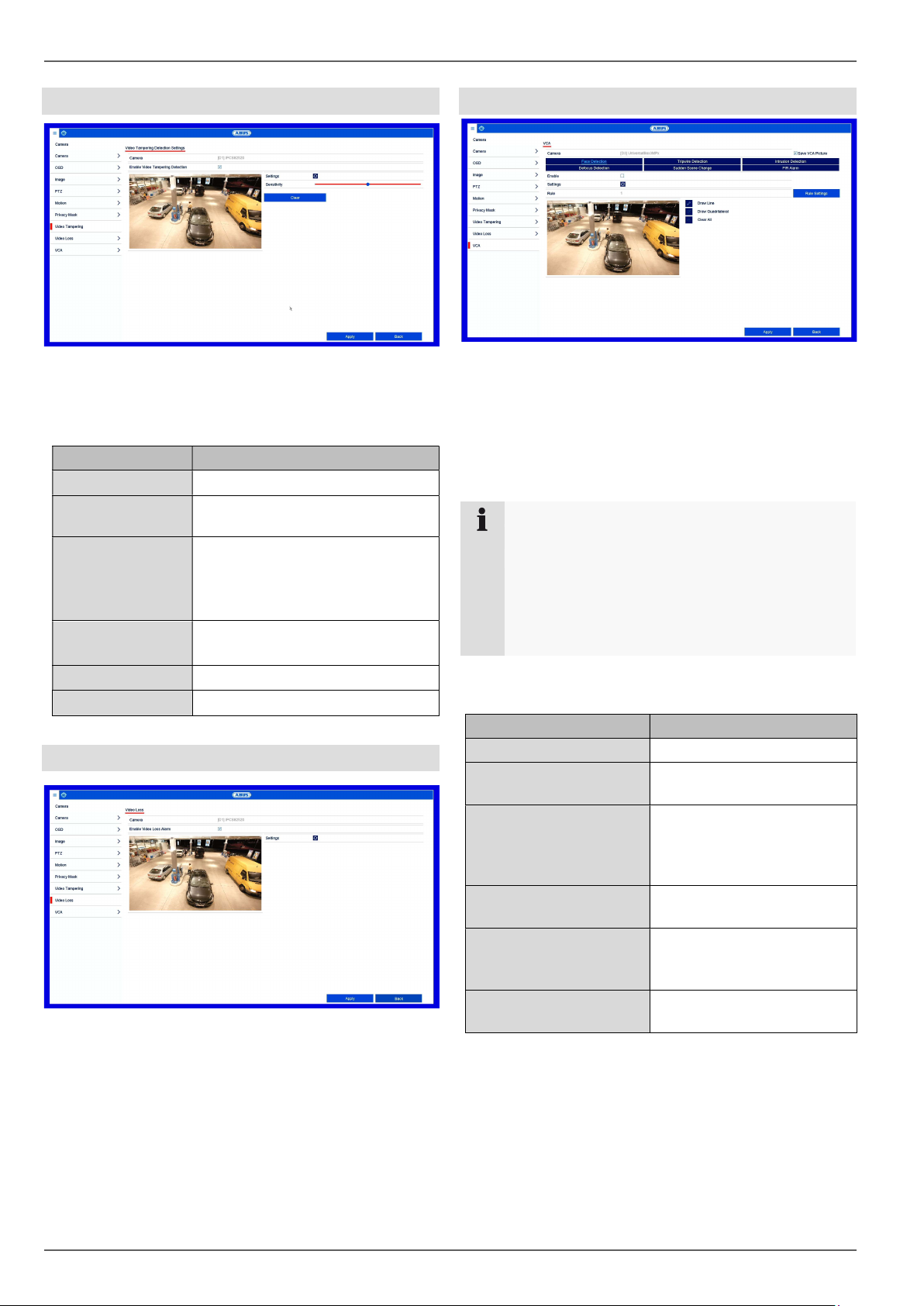
Video Loss ..................................................................................................................................................................... 49
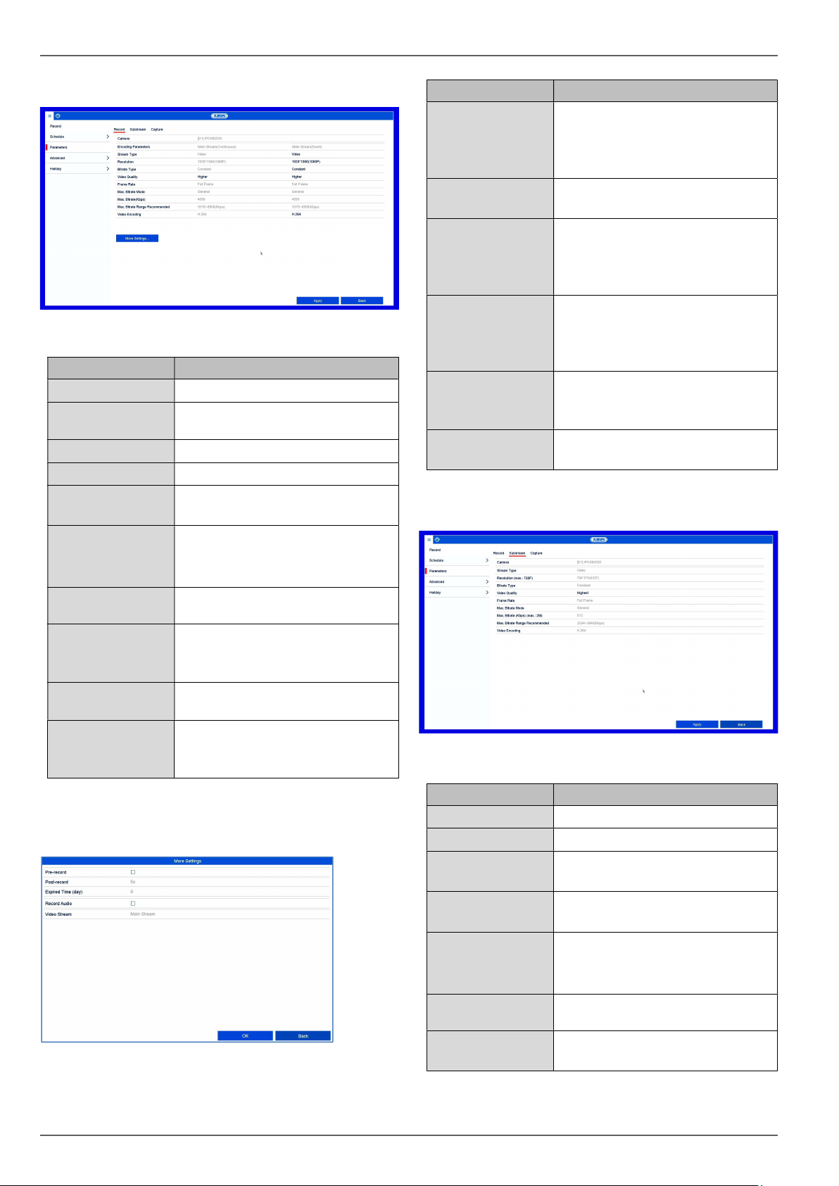
General information on recording .................................................................................................................................. 51
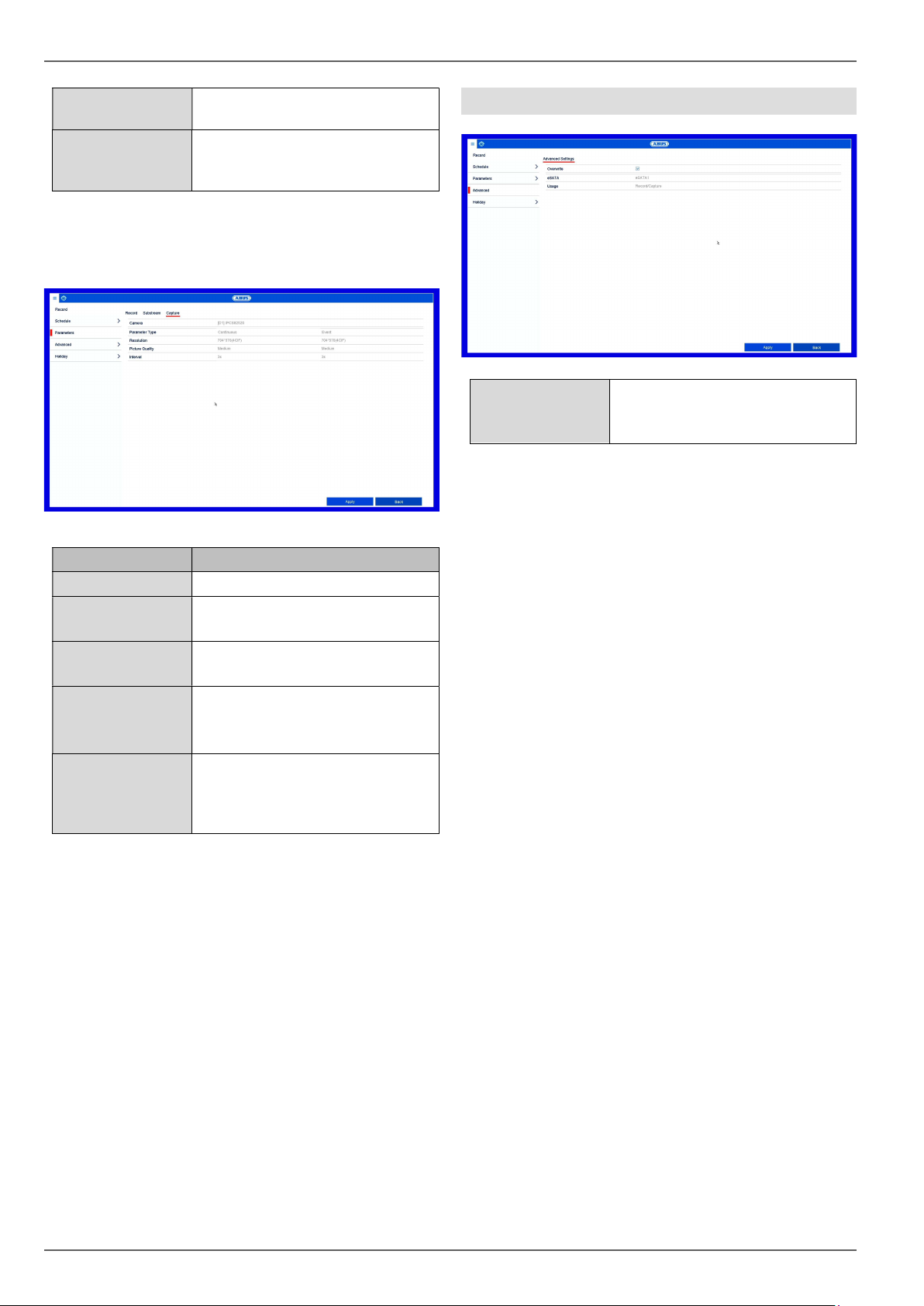
Record tab ..................................................................................................................................................................... 53
General information on HDD.......................................................................................................................................... 56
General .......................................................................................................................................................................... 56
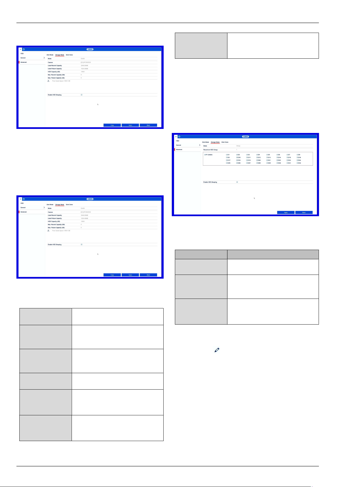
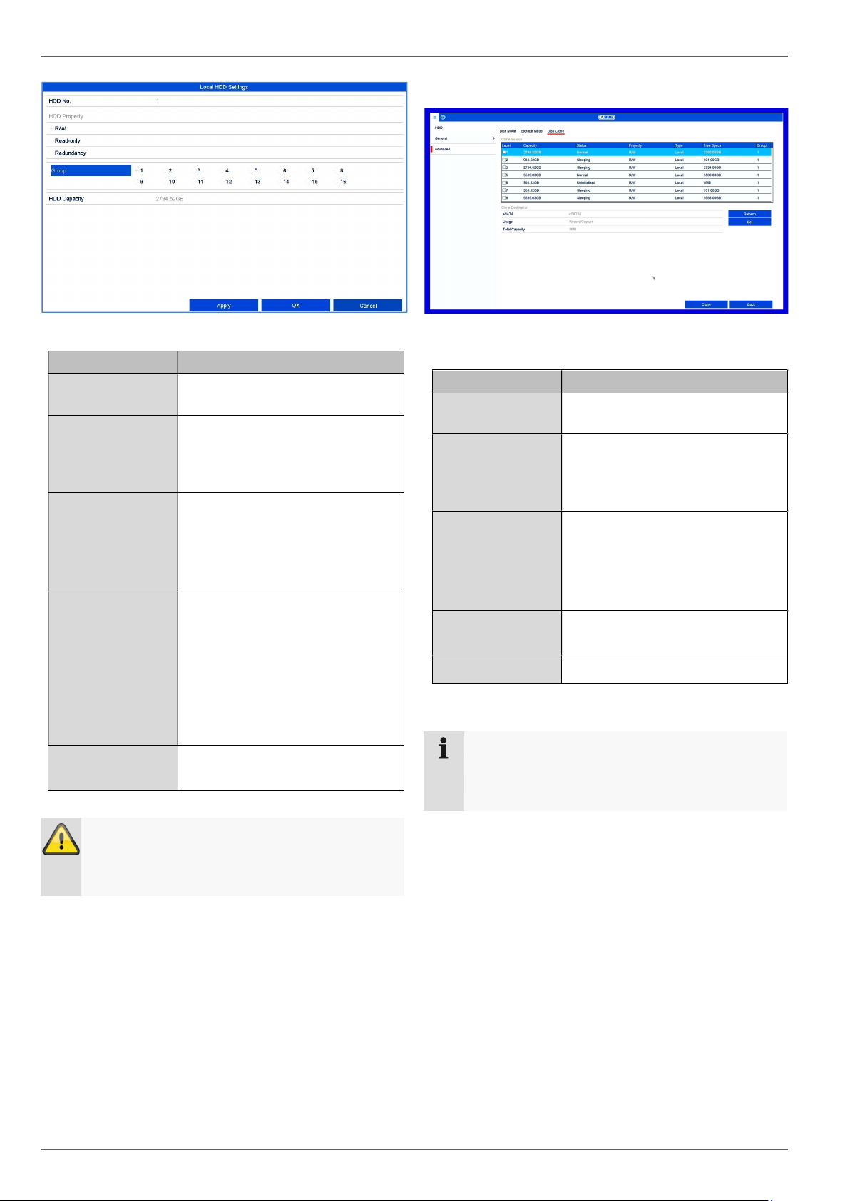
Disk mode tab................................................................................................................................................................ 57
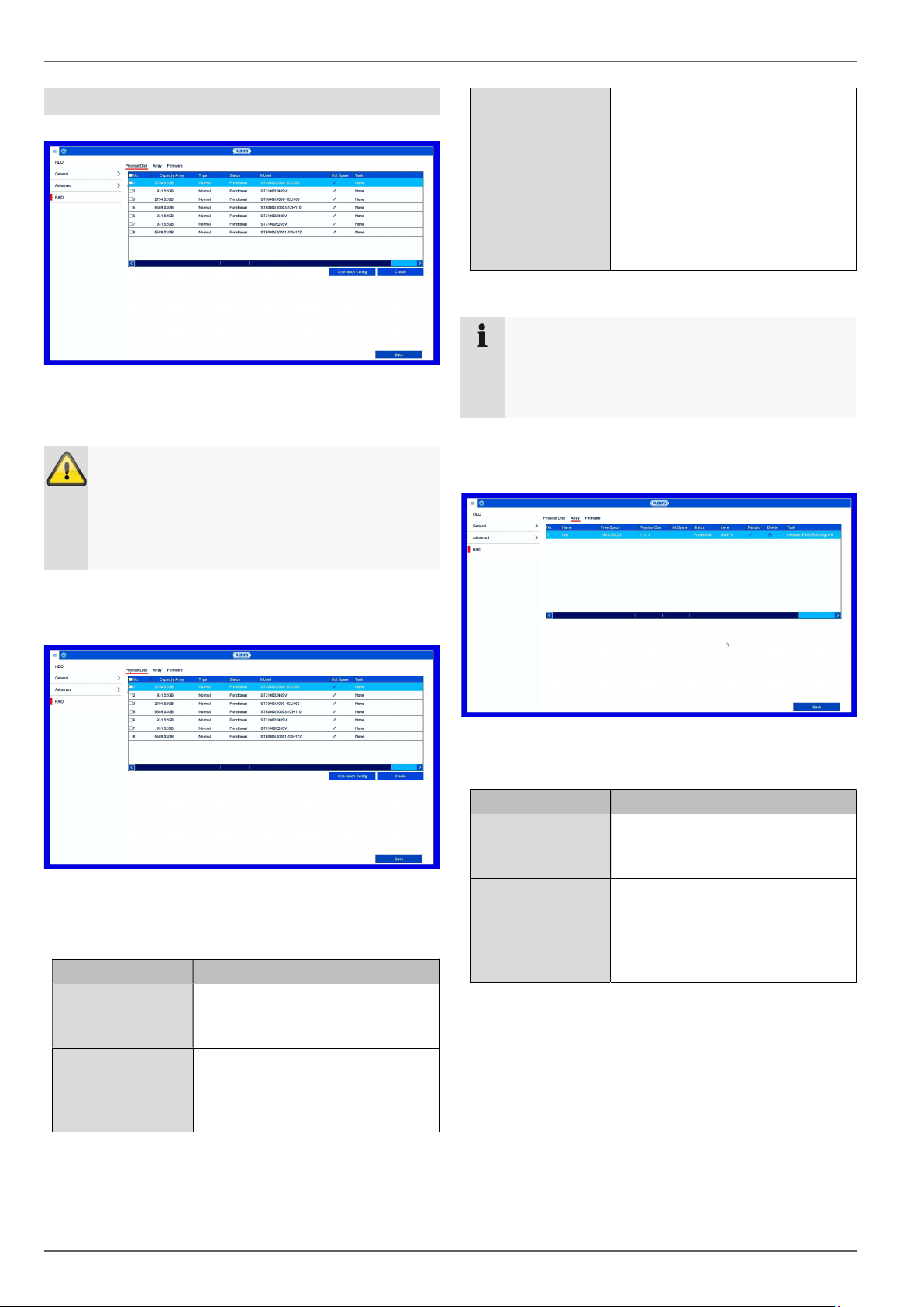
Physical disk tab ............................................................................................................................................................ 60
General information on panic recording ......................................................................................................................... 61
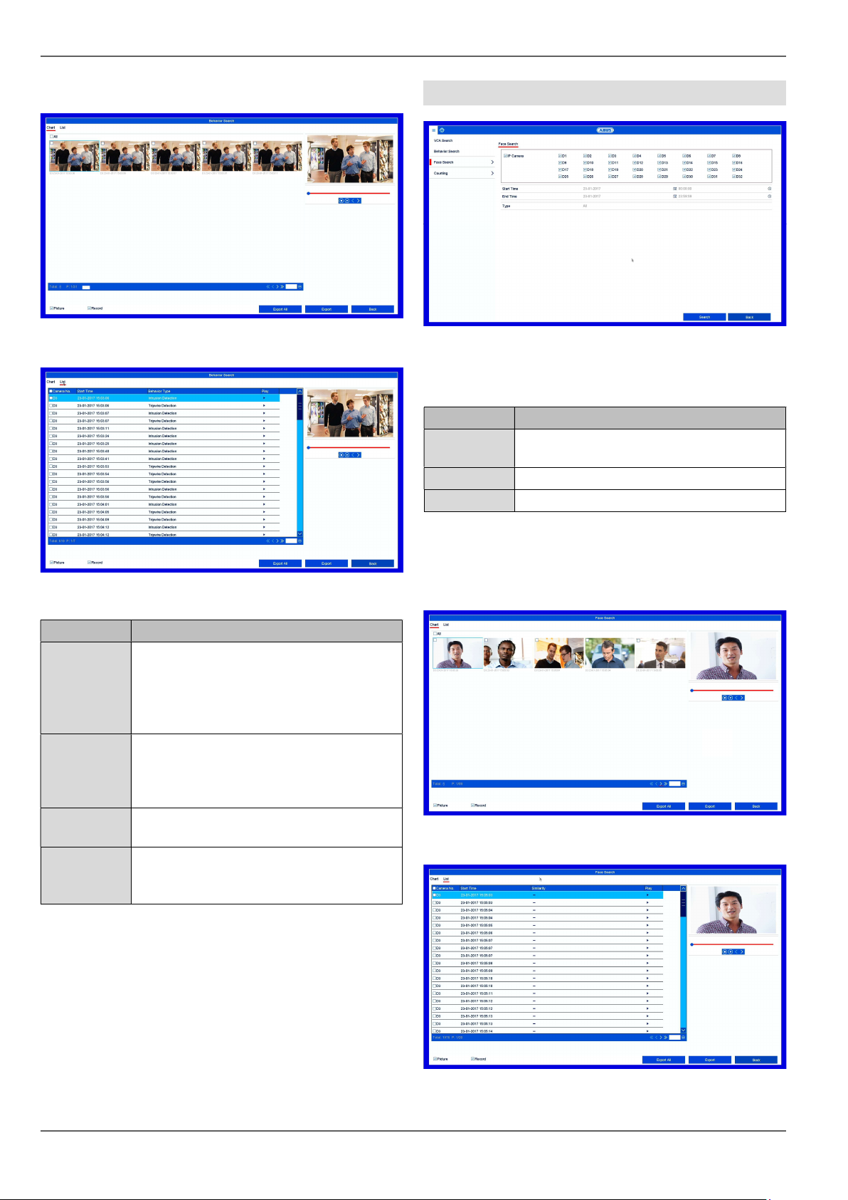
General information on VCA search .............................................................................................................................. 63
Face Search ................................................................................................................................................................... 64
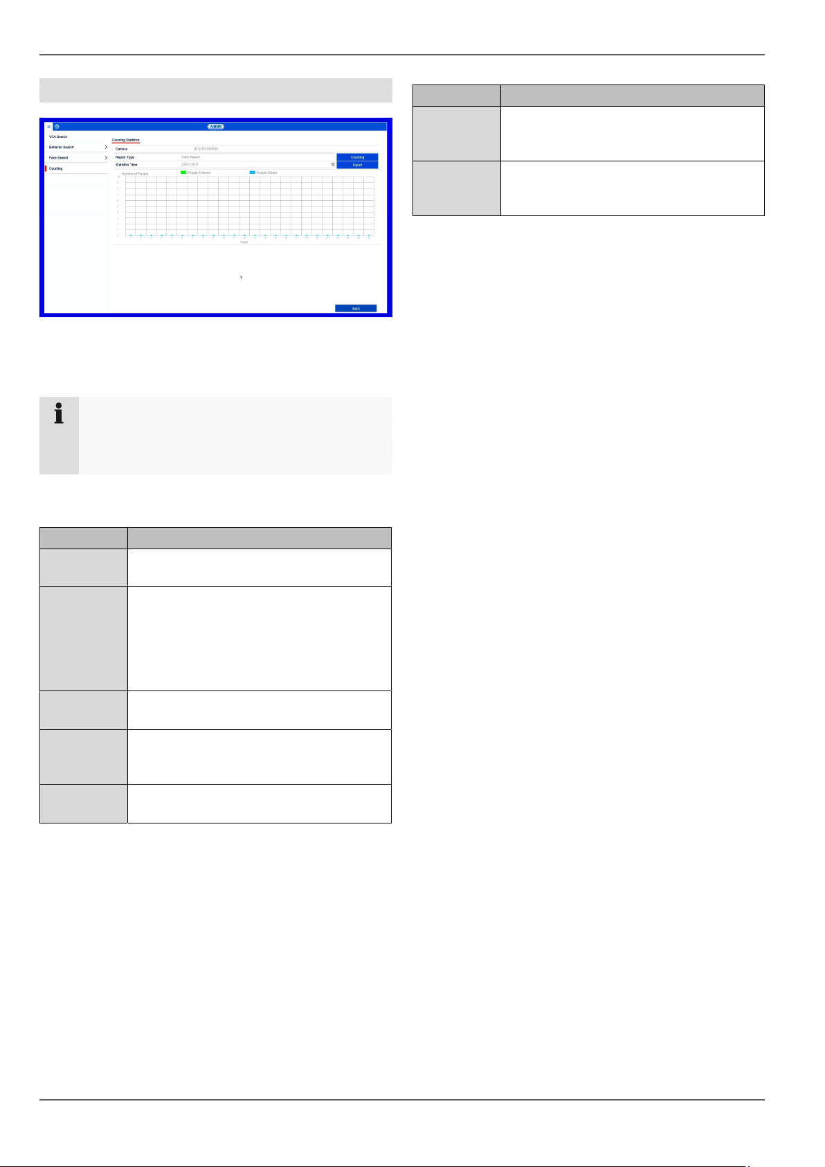
People Counting ............................................................................................................................................................ 65
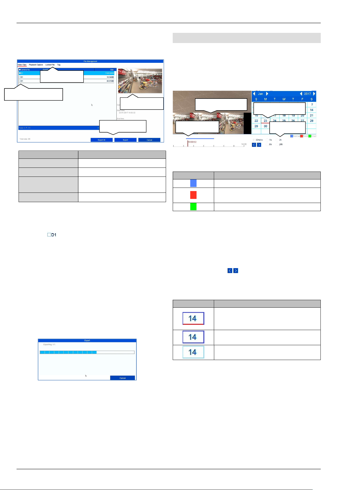
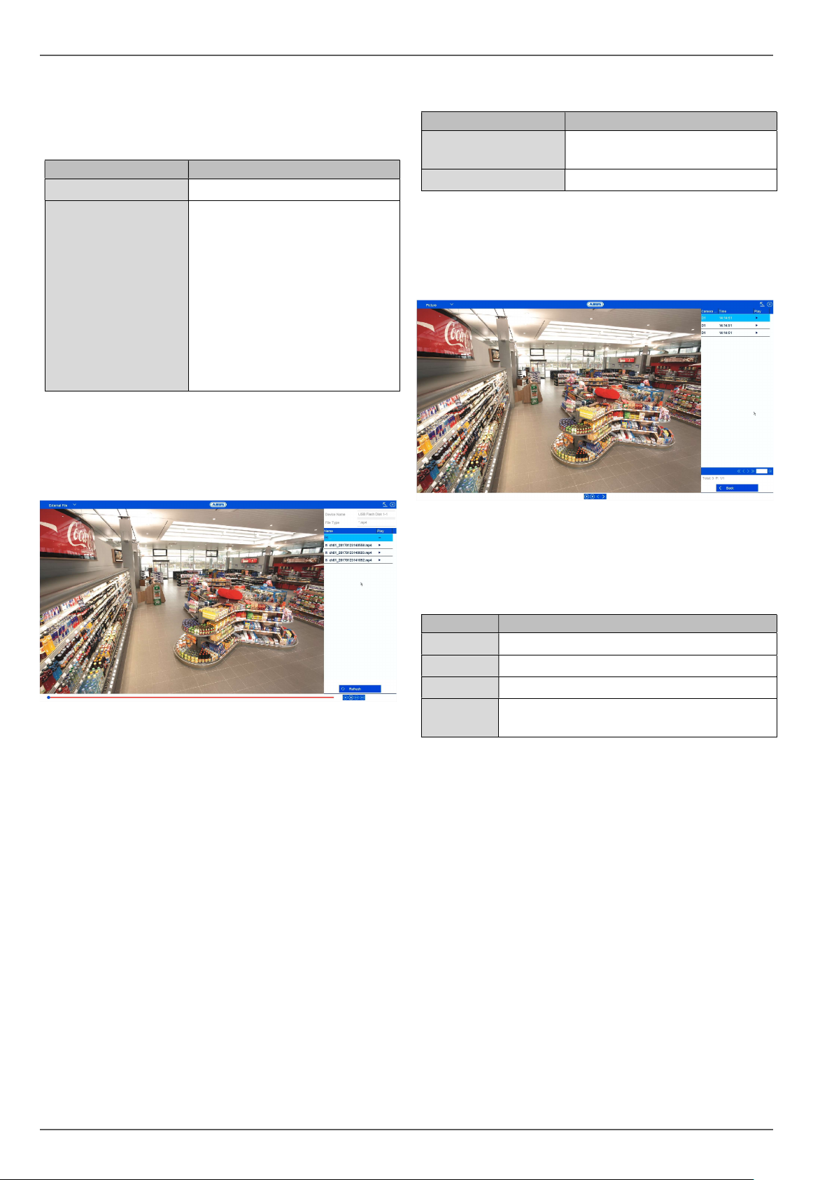
Video Export ................................................................................................................................................................... 66
General information on video export .............................................................................................................................. 66
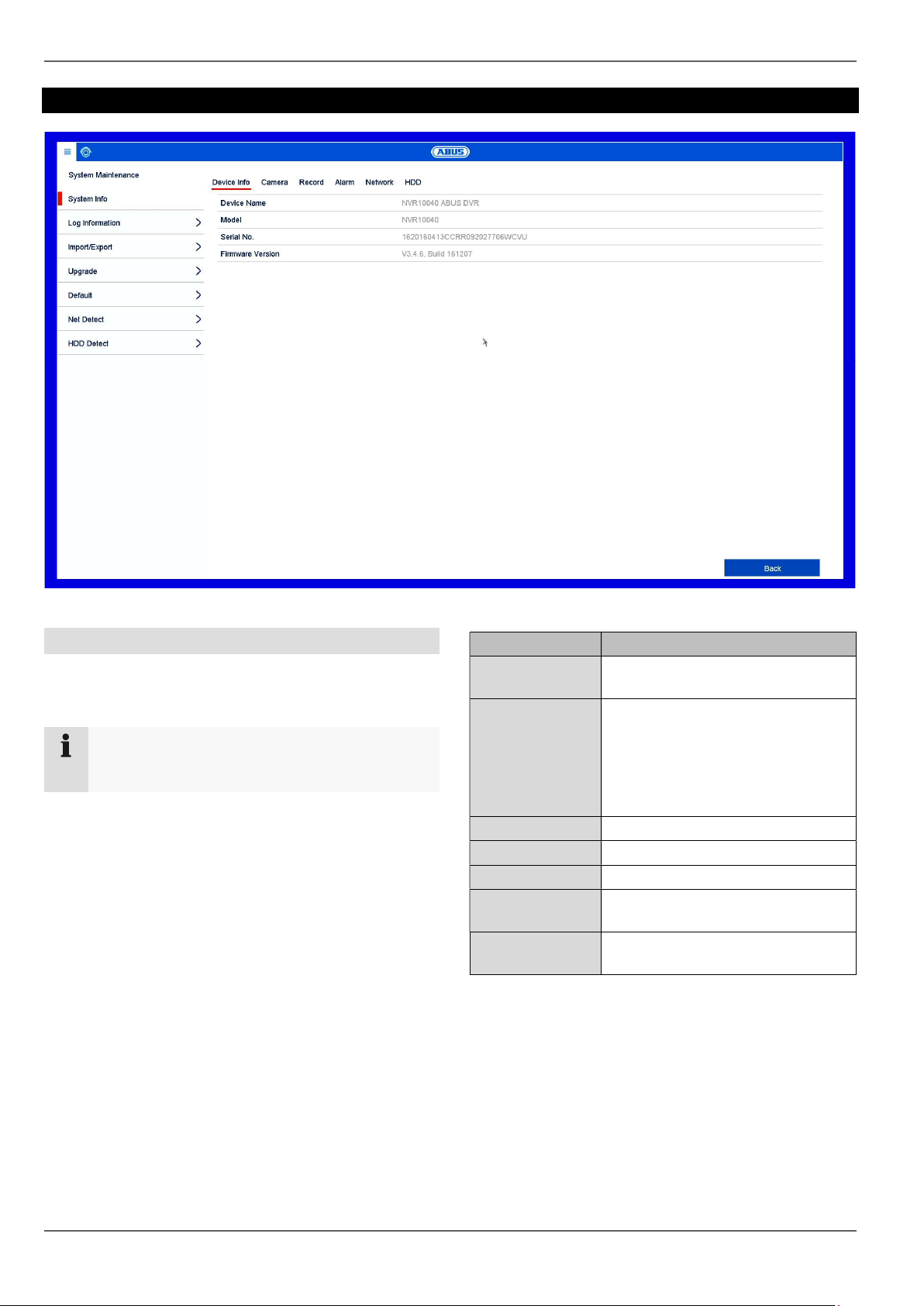
General information on maintenance ............................................................................................................................. 68
System Info .................................................................................................................................................................... 69
Net Detect ...................................................................................................................................................................... 71
Checking the hard disk drive status .............................................................................................................................. 72
Notes on EC directives for waste electrical and electronic equipment .......................................................................... 73
Notes on RoHS EU Directive ......................................................................................................................................... 73
Important safety information
7
Important safety information
Explanation of symbols
The following symbols are used in this manual and on the
device:
Symbol
Signal
word
Meaning
Warning
Indicates a risk of injury or health
hazards.
Warning
Indicates a risk of injury or health
hazards caused by electrical
voltage.
Important
Indicates possible damage to the
device/accessories.
Note Indicates important information.
The following annotations are used in the text:
Meaning
1. …
2. …
Required action to be carried out in a set order
…
…
List without a set order, given either in the text
or warning notice
Intended use
Only use the recorder for the purpose for which it was
built and designed. Any other use is considered
unintended!
This device may only be used for the following
purpose(s):
This recorder is used in combination with video signal
sources (network cameras) and video output devices
(TFT monitors) for object surveillance.
Note
Data storage is subject to national data privacy
guidelines.
When carrying out the installation advise your
customers of the existence of this guideline.
General
Before using this recorder for the first time, please read
the following instructions carefully and observe all
warning information, even if you are familiar with the use
of such recorders.
Warning
All guarantee claims are invalid in the event of
damage caused by non-compliance with this user
manual.
We cannot be held liable for resulting damage.
Warning
In the event of personal or material damage
caused by improper operation or non-compliance
with the safety information, we cannot be held
liable.
All guarantee claims are void in such cases.
Retain this handbook for future reference.
If you sell or pass on the recorder to third parties, you
must include these instructions with the device.
Power supply
Warning
Prevent data loss.
The recorder should only ever be used with a
device that is constantly connected to an
uninterruptible power supply UPS with surge
protection.
Warning
Modifications to the device invalidate the
guarantee.
Important safety information
8
Installation
Observe all safety and operating instructions before
installing the device for the first time.
Only open the housing to install the hard disk drive.
Only install the software on devices that are
expressly suitable for the intended purpose.
Otherwise, damage to the device can occur.
Note
Compatible devices:
- NVR10010
- NVR10020
- NVR10030
- NVR10040
Warning
If in doubt, have the device installed by a
specialist technician.
Children
Do not allow electrical devices to be handled by
children. Do not allow children to use electrical
devices unsupervised. Children may not properly
identify possible hazards. Small parts may be fatal if
swallowed.
Keep packaging film away from children. There is a
risk of suffocation.
This device is not intended for children. If used
incorrectly, parts under spring tension may fly out and
cause injury to children (e.g. to eyes).
EU Directives
This device complies with the requirements of the EU
Low Voltage Directive (2014/35/EU), the EMC
Directive (2014/30/EU) and the RoHS Directive
(2011/65/EU). The declaration of conformity can be
obtained from:
ABUS Security-Center GmbH & Co. KG
Linker Kreuthweg 5
86444 Affing
GERMANY
To ensure this condition is maintained and that safe
operation is guaranteed, it is your obligation to observe
this user guide.
Please read the entire user manual carefully before
putting the product into operation, and pay attention to all
operating instructions and safety information.
All company names and product descriptions are
trademarks of the corresponding owner. All rights
reserved.
If you have any questions, please contact your specialist
installation contractor or specialist dealer.
Disclaimer
This user guide has been produced with the
greatest of care. Should you identify any
omissions or inaccuracies, please contact us at
the address shown on the back of the guide.
ABUS Security-
Center GmbH does not accept any
liability for technical and typographical errors, and
reserves the right to make changes to the product
and user guides at any time and without prior
warning. ABUS Security-Center GmbH is not
liable or responsible for direct or indirect damage
resulting from the equipment, performance and
use of this product. No guarantee is made for the
contents of this document.
Do not allow electrical devices to be handled by children.
Do not leave children unsupervised.
Compatibility
9
Compatibility
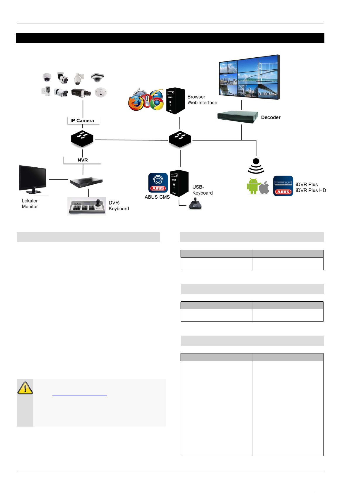
General
ABUS embedded recorders are compatible with a
variety of cameras and additional components. Check
the compatibility with your device and limitations to the
use of the components before use.
Some functions of this recorder (firmware) depend on
the connected devices (e.g. fisheye view of
hemispheric cameras or PTZ cameras).
Please keep in mind that older devices may not be
supported or may be only partially supported.
Note
Check http://www.abus.com to find any additional
information on compatibility with your
camera/recorder.
The following tables show the current versions at
the time of publication of this guide (Q1/2017).
Compatible recorders
Device type
Item number
NVR NVR10010, NVR10020,
NVR10030, NVR10040
Compatible video walls/decoders
Device type
Item number
Video Wall Decoder TVAC26100, TVAC26110,
TVAC26120, TVAC26130
Compatible IP cameras
IP camera type
Item number
IP Camera
TVIP11560, TVIP41500,
TVIP41560, TVIP52502,
TVIP61500, TVIP61550,
TVIP61560, TVIP70000,
TVIP72000, TVIP91100,
TVIP91300, TVIP91600,
TVIP91700, TVIP92100,
TVIP92300, TVIP92500,
TVIP92600, TVIP92610,
TVIP92700, IPCA33500,
IPCA53000, IPCA63500,
IPCA66500, IPCA73500,
IPCA76500, IPCB42500,
IPCB42550, IPCB71500,
IPCB72500, IPCS10020,
IPCS62520, IPCS72520
Compatibility
10
IP camera PT/Z
TVIP21560, TVIP41660,
TVIP81000, TVIP81100,
TVIP82000, TVIP82100,
IPCS82502, IPCS82500
IP camera Hemispheric
TVIP82900, TVIP83900,
TVIP86900
ONVIF See http://www.abus.com
(recorder download area)
RTSP RTSP streaming profile
Compatible keyboards
Device type
Item number
PTZ/DVR control panel TVAC26000
USB keyboard
(only in connection with
ABUS CMS)
TVAC26010
Compatible software
Device type
Item number
ABUS CMS TVSW11000
iDVR Plus
(Smartphone)
APP12300 (iOS)
APP12500 (Android)
iDVR Plus HD
(Tablet)
APP12400 (iOS)
APP12600 (Android)
ABUS IP installer TVSW12000
Supported camera functions
Device type
Item number
Smart Search
(possibly not all functions
depending on the model)
IPCA33500, IPCA53000,
IPCA63500, IPCA66500,
IPCA73500, IPCA76500,
IPCS10020, IPCA62520,
IPCA72520, IPCA66500,
IPCA73500, IPCA76500,
IPCB42500, IPCB42550,
IPCB71500, IPCB72500,
IPCS10020, IPCS62520,
IPCS72520
Virtual alarm inputs and
outputs
IPCA33500, IPCA53000,
IPCA63500, IPCA66500,
IPCA73500, IPCA76500,
IPCS10020, IPCA62520,
IPCA72520, IPCA66500,
IPCA73500, IPCA76500,
IPCB42550, IPCB71500,
IPCB72500, IPCS10020,
IPCS62520, IPCS72520
VCA
(restrictions in creating
the VCA event images
depending on the model)
IPCA33500, IPCA53000,
IPCA63500, IPCA66500,
IPCA73500, IPCA76500,
IPCA62520, IPCA72520,
IPCA66500, IPCA73500,
IPCA76500
Pre-play storage
Unlike flexible PC systems, embedded recorders have
a hardware configuration which is tailored to their
intended purpose. As a consequence, the desired
recording schedule cannot always be achieved in the
special case of pre-play recordings. The available
working memory is a crucial parameter for the pre-play
recording schedule. Depending on the model,
embedded recorders have between 512 MB–2 GB of
working memory to manage all the background
processes of all cameras. In order to create pre-play
recordings, the information for each individual camera,
depending on the resolution, bitstream settings and
pre-play schedule, must be permanently kept in the
memory. A pre-alarm memory of a few seconds is
already hard to achieve with the use of 1080p
cameras. The higher the resolution of the cameras and
the more cameras connected to the recorder, the lower
the chance of having enough memory ready for all
cameras. Due to the variety of models and
configuration settings, as well as the complexity of the
evaluation of current scenes, we cannot provide a
reliable value for the pre-alarm memory. As a result,
we recommend using continuous recording for critical
cameras and then using the Smart Search to easily
filter out events.
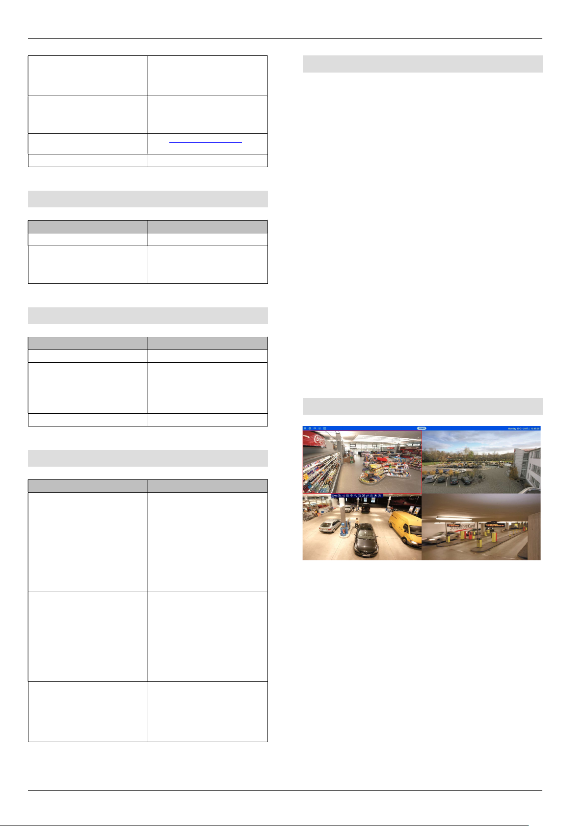
Image display
In order to display the IP camera video streams
(including live images and the playback of recordings)
via the local video output on the recorder
(VGA/HDMI/BNC), the digitally compressed data from
the recorder must be “decoded”. This process requires
processing power on the recorder sufficient for the
camera’s resolution. The higher the resolution and
bitrate of the camera stream, the higher the required
processing power on the recorder for the decoding
process.
Compatibility
11
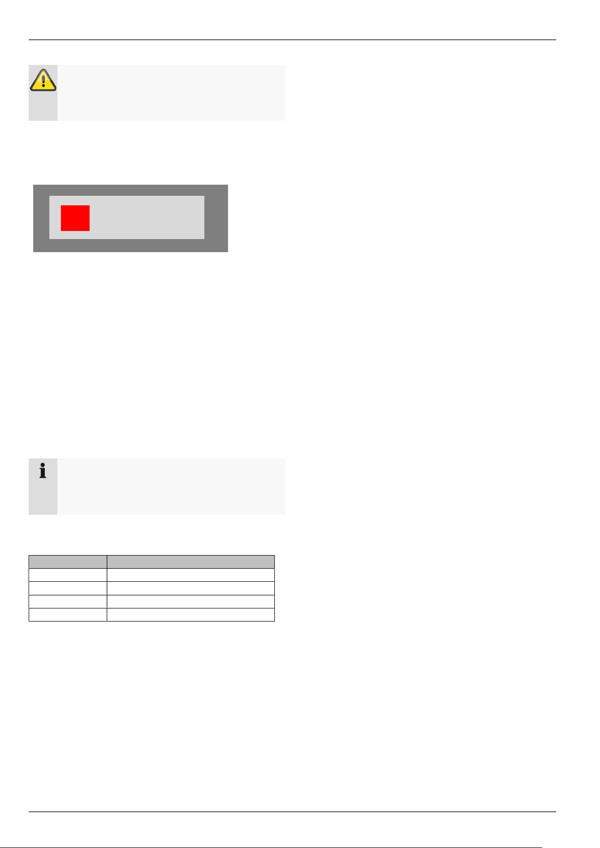
If the number of camera streams to be displayed
exceeds the decoding performance of the recorder, the
following notification will appear on the monitor:
For this reason, the substream of each camera will be
displayed automatically in the multi-view live views with
more than 4 channels (greater than 2x2). The
substream of a camera is therefore usually set to 720p
or lower.
In the playback view, the cameras will be played in
their respective recording quality (main stream).
Depending on the application and camera type, it is
possible that not all cameras will be able to be
displayed at once. As such, you should split up the
cameras into different views in order to avoid any
limitations.
The following stream configurations are possible for
local image output:
During remote playback by browser, CMS software or
app, the remote device undertakes the decoding
process (in order to display the images on the PC
monitor/smartphone) and therefore does not impact on
the processing power of the recorder.
Warning
When problems/limitations in the local live image
view occur when the device is operating, bear this
information in mind.
Note
The NVR systems NVR10010, NVR10020,
NVR10030 and NVR10040 have a decoding
performance of 16 x 1080p.
Resolution
Number of decodable cameras
720p
64 cameras
1080p
16 cameras
3
MPx
8 cameras
6
MPx
4 cameras
NO RESOURCE
External I/O connections and wiring
12
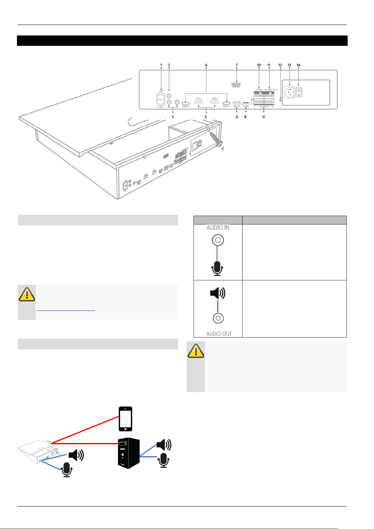
External I/O connections and wiring
General
The ABUS embedded recorders are equipped with
external interfaces for the control of alarm contacts, PTZ
cameras, keyboards and audio devices. The structure
level of the connections depends on the recorder model.
The larger the structure level of the recorder, the more
connections are normally present on the device.
Note
In your recorder’s quickstart manual or at
http://www.abus.com, you will find an exact listing
of the external interfaces in the technical data.
Audio connections/2-way audio
The audio connections on the recorder are only used for
remote 2-way audio communication via a network
connection. This can take place via the web interface on
the recorder, via the ABUS CMS software or via the iDVR
Plus app. The system configuration for this purpose is as
follows:
Note
If the 2-way audio communication takes place via
a PC, you must ensure that a microphone and
loudspeaker are connected. In order to use the
web browser function, the ABUS recorder plug-in
must be installed.
Connection
Description
RCA audio input for the connection
of a separate microphone for 2-
way audio communication. If the
volume is too low, use an
additional preamplifier to raise the
signal levels of the microphone
input.
RCA audio output for the
connection of a separate
loudspeaker for 2-way audio
communication. Passive
loudspeakers must be connected
via a locked amplifier.
Network
Audio OUT
Audio IN
Line OUT
Mic IN
External I/O connections and wiring
13
Alarm inputs
The alarm inputs on the recorder are used for event
control via externally wired detectors (door contacts,
motion detector, smoke detector, light barriers, etc.). On
the recorder side, the inputs can be used to activate a
recording, alert via CMS or send an alarm email, among
other things. The alarm inputs are purely switch contacts
(Normally Open/Normally Closed) which must not be
voltage controlled.
Note
Following the connection of the detector to the
alarm input of the recorder, the behaviour in the
normal state (NO/NC) and the event reaction must
be programmed in the settings menu.
Alarm outputs
The alarm outputs on the recorder are used for the action
control of externally wired devices/actuators (sirens,
lamps, door openers, etc.). The alarm output switching
takes place via integrated relays on the recorder. In order
to prevent damaging the relay/recorder, the device’s
maximum switching power must not exceed the specified
values of 12 V / 1 A.
Note
After the actuator has been connected to the
alarm input of the recorder, the event reaction
must be programmed in the settings menu.
RS-485 output (NVR10030/NVR10040)
The RS-485 output on the recorder is used to control
analogue PTZ cameras.
IP cameras with an integrated PTZ function are fully
controlled via the network.
The use of the interface is intended as an alternative for
the use of IP cameras with external motor control.
Connection
Description
Depending on the recorder model,
1–16 inputs are available. First,
plug the detector contact in an
open input (IN1-16) and then
connect the grounding contact (G).
Connect more detectors in the
same way:
IN1 G
IN2 G
IN3 G
….
IN16 G
It does not matter whether you
connect all detectors to one
grounding contact or divide them
up among the available contacts.
Use terminal blocks in order to
connect multiple detectors to one
grounding contact.
Co
nnection
Description
Depending on the recorder model,
1–8 outputs are available. First,
plug the actuator/device in an
open output (OUT1-8) and then
connect the grounding contact (G).
Connect further actuators in the
same way:
OUT1 G
OUT2 G
OUT3 G
….OUT8 G
It does not matter whether you
connect all actuators to one
grounding contact or divide them
up among the available contacts.
Use terminal blocks in order to
connect multiple actuators to one
grounding contact.
Connection
Description
Connect the PTZ control by using
the Transmit and Receive pins.
Only available on
NVR10030/NVR10040 !
Detector
s
Actuator
_
_
-
External I/O connections and wiring
14
Keyboard output
The keyboard output on the recorder is used to control
the recorder using the optional keyboard (TVAC26000).
The local recorder functions can alternatively (instead of
using a mouse) be called up by using the external
keyboard.
Connection
Description
Connect the keyboard using
connections D- and D+ on the
interfaces DVR-CON Ta and Tb.
Introduction
15
Introduction
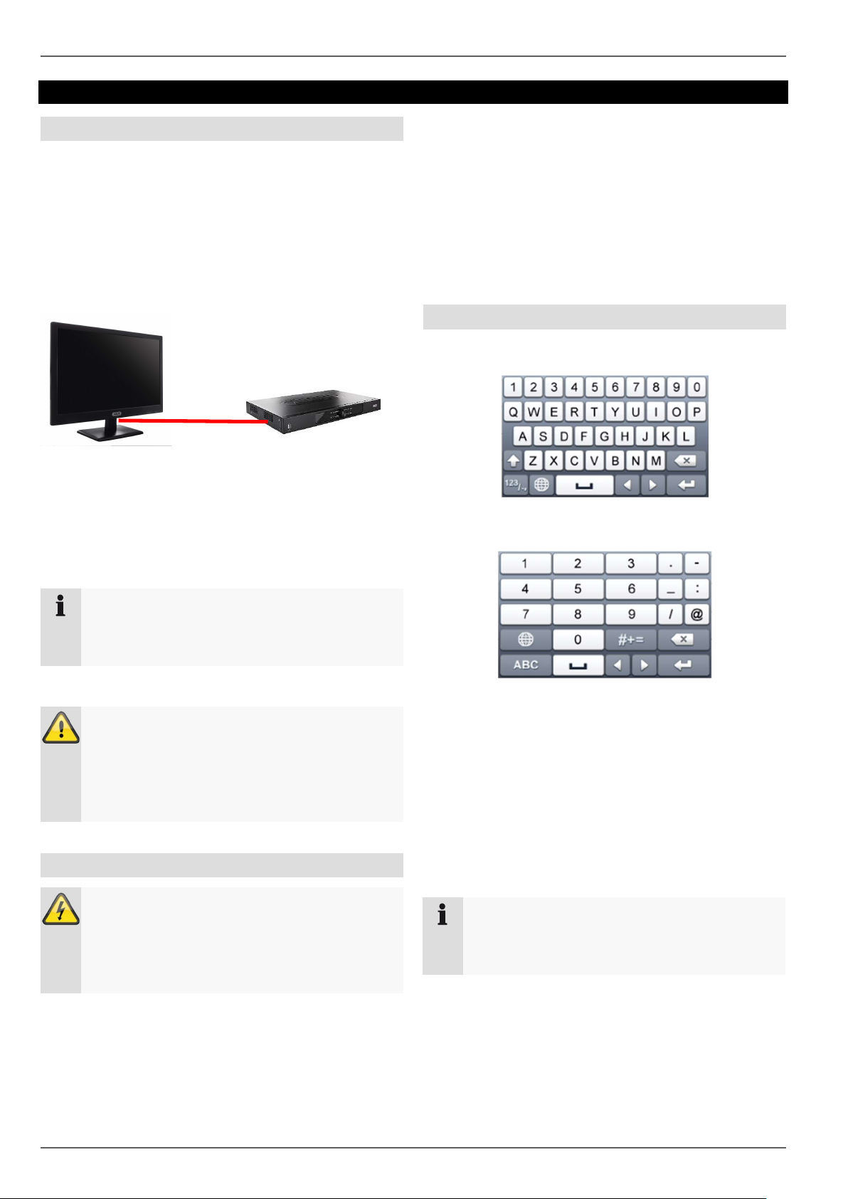
General information
This handbook describes the commissioning and use of
the ABUS embedded recorder via the local user
interface.
For this purpose, the recorder must be connected to a
monitor using the VGA/HDMI interface. During
operation, use the USB mouse which was included in
the scope of delivery.
We recommend that you complete the initial setup using
the local interface in order to set up basic settings like
the network address and the hard disc drive
configuration.
Note
Before the initial commissioning, make sure that
both the recorder and the IP cameras are
connected using the same network.
Note
Make sure that the recorder is connected directly
to your CCTV network (Switch) via a network
cable. For the best possible performance, do not
use a Wi-Fi connection between the recorder and
the CCTV network.
Starting the device
Important:
The device may only be connected to a mains
voltage supply as specified on the type plate.
For security, use an uninterruptable power supply
UPS.
When the device is connected to the power supply, it
starts up automatically and the blue status LED blinks.
1. During the start-up procedure, the device carries
out a self-test (blue LED will blink).
2. The start-up procedure is complete when the
blue LED is lit continuously.
3. Subsequently, the setup wizard (during the first
system start) or the live image display of the
cameras that have been set up will appear (after
the setup wizard has been completed
successfully).
On-screen keyboard
If you click with the mouse in a text input field, the on-
screen keyboard appears:
For simple figure input, the following on-screen keyboard
appears:
The keys have exactly the same function as a computer
keyboard.
To input a figure, click on it with the left mouse key.
To finish the entry, click on Enter.
To delete the figure in front of the cursor, click on .
To switch between upper and lower case text, click
on the framed a. The active setting is indicated above
the keyboard.
To cancel an entry, or to leave the field, click on ESC.
Note
Be aware that alterations to the recorder carried
out via the software must be accepted by clicking
“Apply”/“Confirm” before leaving the tab or menu.
Introduction
16
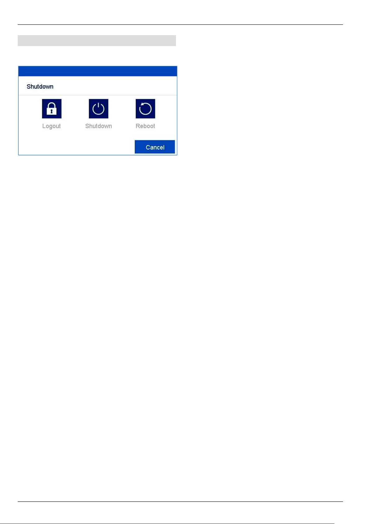
Switching off the device, locking, rebooting
In the main menu, click on Shutdown. The overview
appears.
To switch off, select the Shutdown option and
confirm the query with Yes. The device is switched
off.
Do not press any key during the switch off
procedure.
Now pull out the plug of the power supply unit.
3. To lock the system, select the left hand symbol
Logout. The user interface is locked. To reach the
menu, a password must be entered.
4. To reboot, select the right hand symbol Reboot. The
device carries out a reboot.
Setup wizard
17
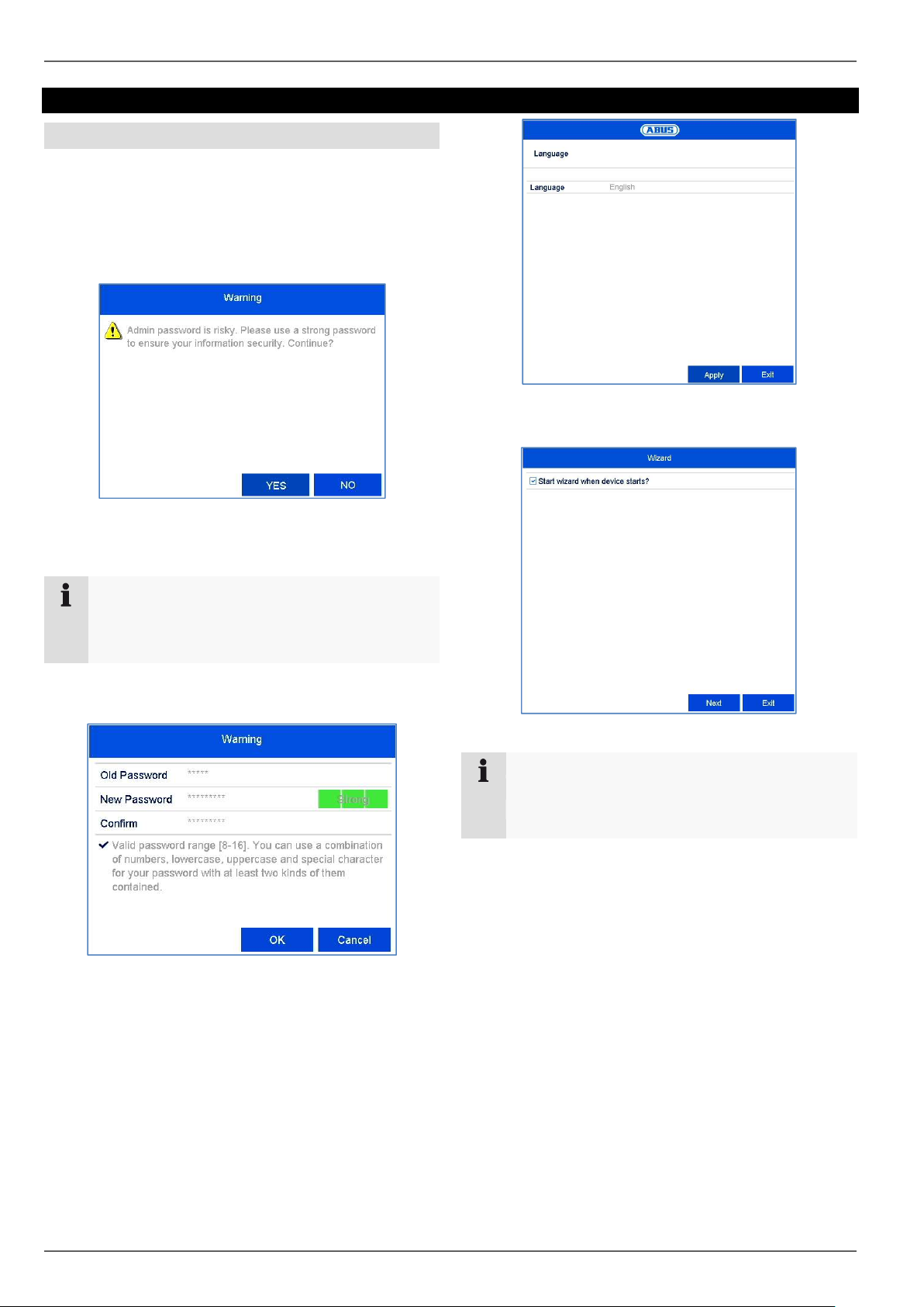
Setup wizard
Setting up the system
The setup wizard guides you through the required basic
settings for the system. The network video recorder will
then be ready for recording and monitoring.
After turning on for the first time, the language selection
appears:
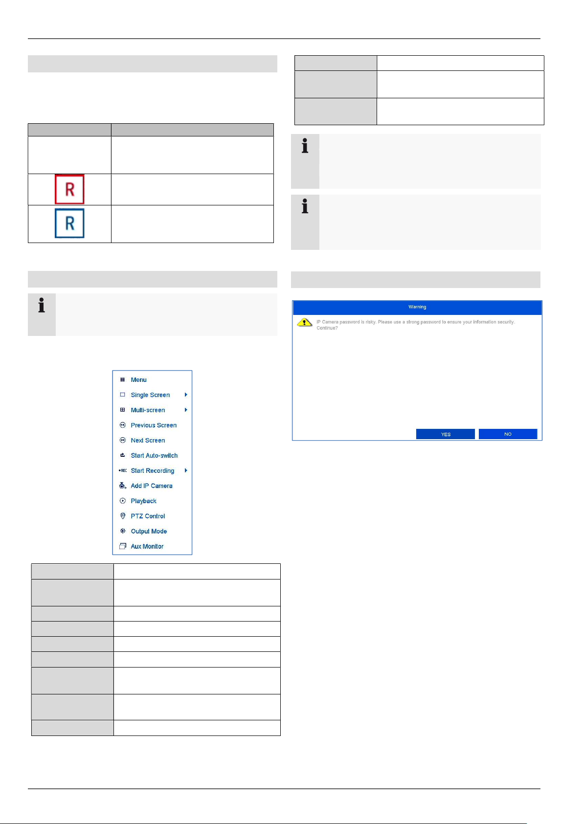
The recorder’s default password is “12345”. This
is a temporary password and must be changed
for security reasons.
Note
If the password is not changed, a warning notice
will appear until the password has been changed
in line with the security policy.
Change the password immediately by clicking on
“Yes”.
Old password: Enter the default password
New password: Enter a new password, bearing
the security policy in mind.
Confirm the password by entering it again and
clicking OK.
Click on the input field and select your language
from the list.
Click on Next to start the wizard.
Note
After the system has been set up the “checkbox”
can be deactivated: the box will be hidden and the
wizard no longer starts automatically.
Setup wizard
18
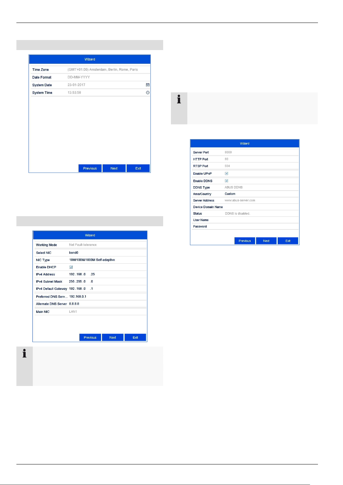
System time and date
Enter the system time consisting of date and
time.
Finish the setting by clicking
on Next.
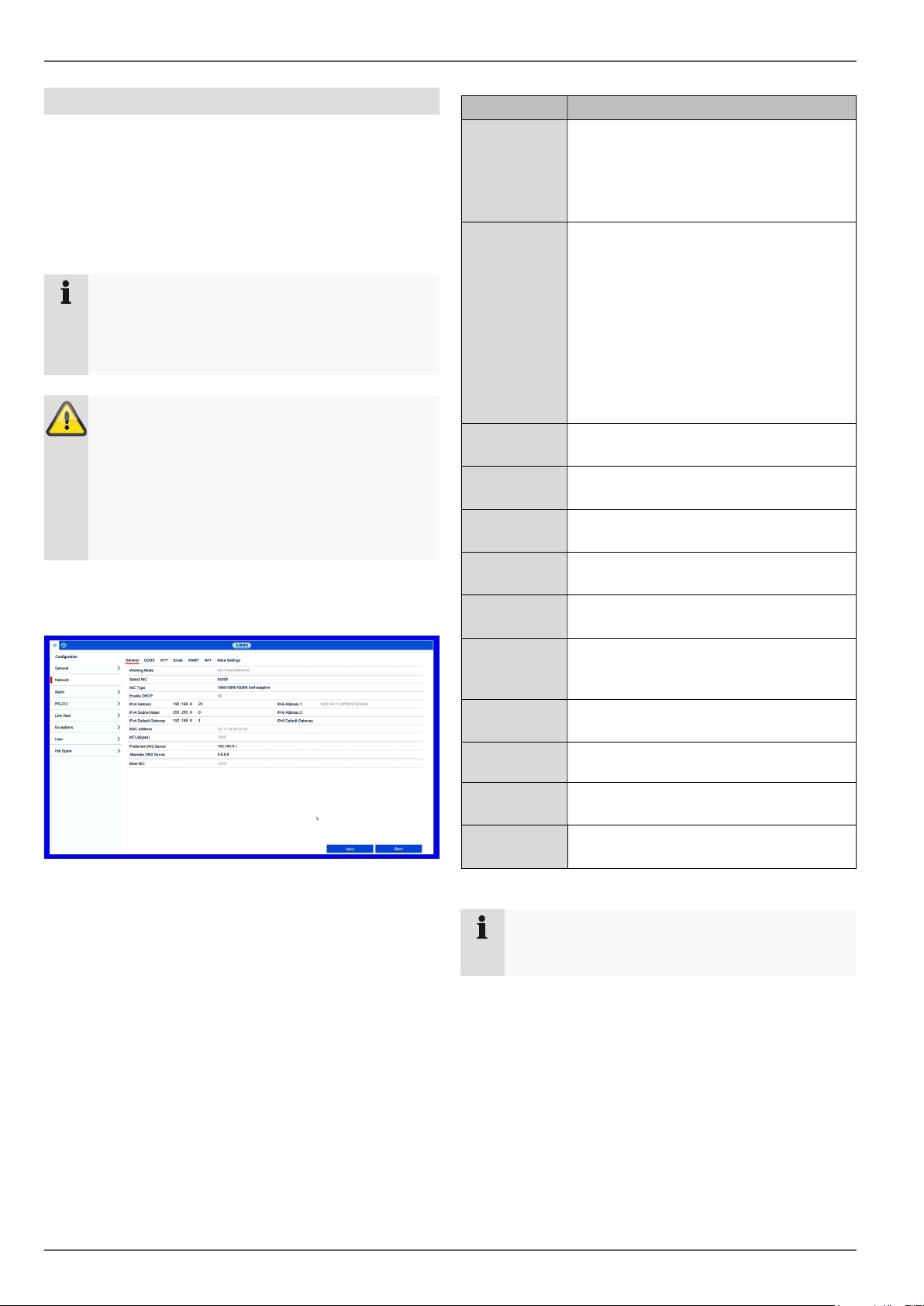
Network settings
Note
Ask the network administrator responsible
whether the DHCP can be selected or the IP
address and additional settings have to be done
manually.
DHCP active: if the DHCP has been set up in the
network router, enable the DHCP “checkbox”. All
network settings are then completed
automatically.
DHCP inactive: enter the data manually (IPv4
address, IPv4 subnet mask as well as the default
set up for the IPv4 Gateway = IPv4 address of
the router, DNS server). A typical address
assignment could appear as follows:
IPv4 address: 192.168.0.50
IPv4 subnet mask: 255.255.255.0
IPv4 default gateway: 192.168.0.1
Preferred DNS server: 192.168.0.1
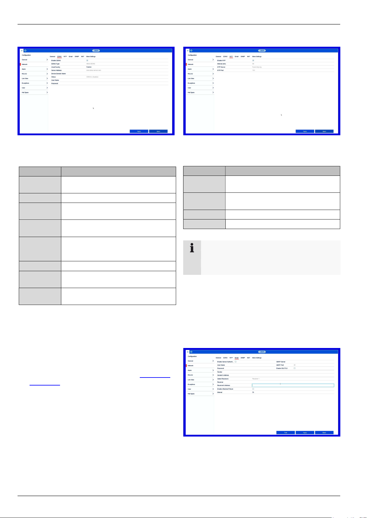
Adjust the network ports here.
To set up remote access through the internet,
activate DDNS using the “checkbox”.
Click on the input field and select the DDNS type.
When using public DDNS providers, save the
server address and the Device Domain Name,
user name and password.
When using the ABUS server as the DDNS
provider, no extra parameters are necessary.
Click on Next.
Note
When the device is accessed remotely via the
internet, it should be given a fixed network
address.
Setup wizard
19
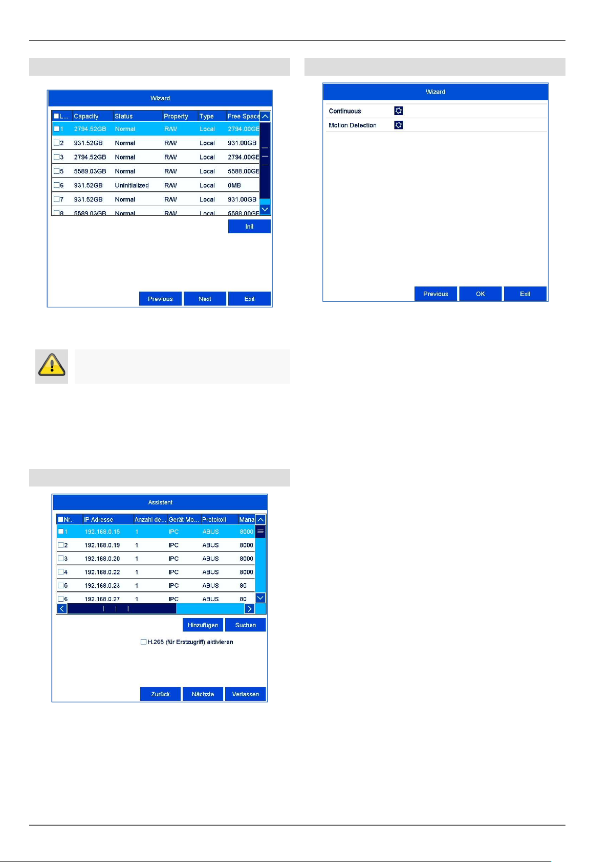
Hard disk drive management
To set up a hard disk drive, enable the “checkbox”
with a left click and then click on Init.
Click on OK to acknowledge the security prompt. The
hard disk drive is set up for use. Progress is shown
on the status bar.
Finish the setting with OK and then click on Next.
Camera assistant
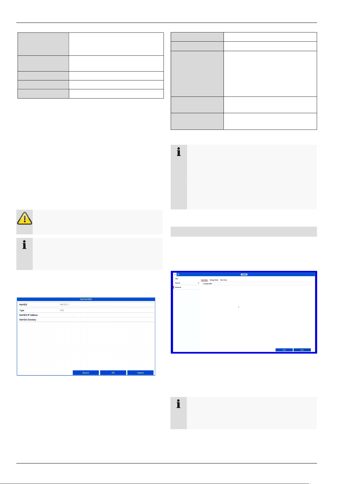
Click on Search to display the cameras on your
network.
To add network cameras, activate the desired
cameras and click on Add.
Click on Next to continue with the setup.
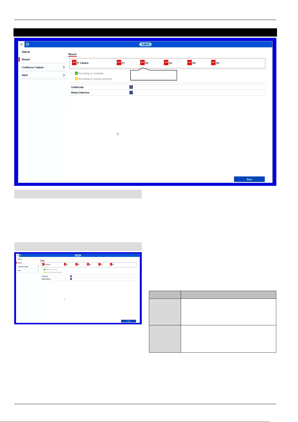
Camera recording
Select the recording type. It is possible to select
between "Continuous" and "Movement detection".
Complete the setting and the setup wizard with OK.
Warning
This will delete all data found on the disc.
Live view
20
Live view
General information on live image
Live view starts automatically when the device is
switched on. The live image function provides the option
to display live images and execute camera commands
from all cameras connected to the recorder. Alongside
playback, this is one of the core functions of the recorder.
By double clicking with the left mouse button, you can
display the selected camera image in full screen or
switch back to the original view.
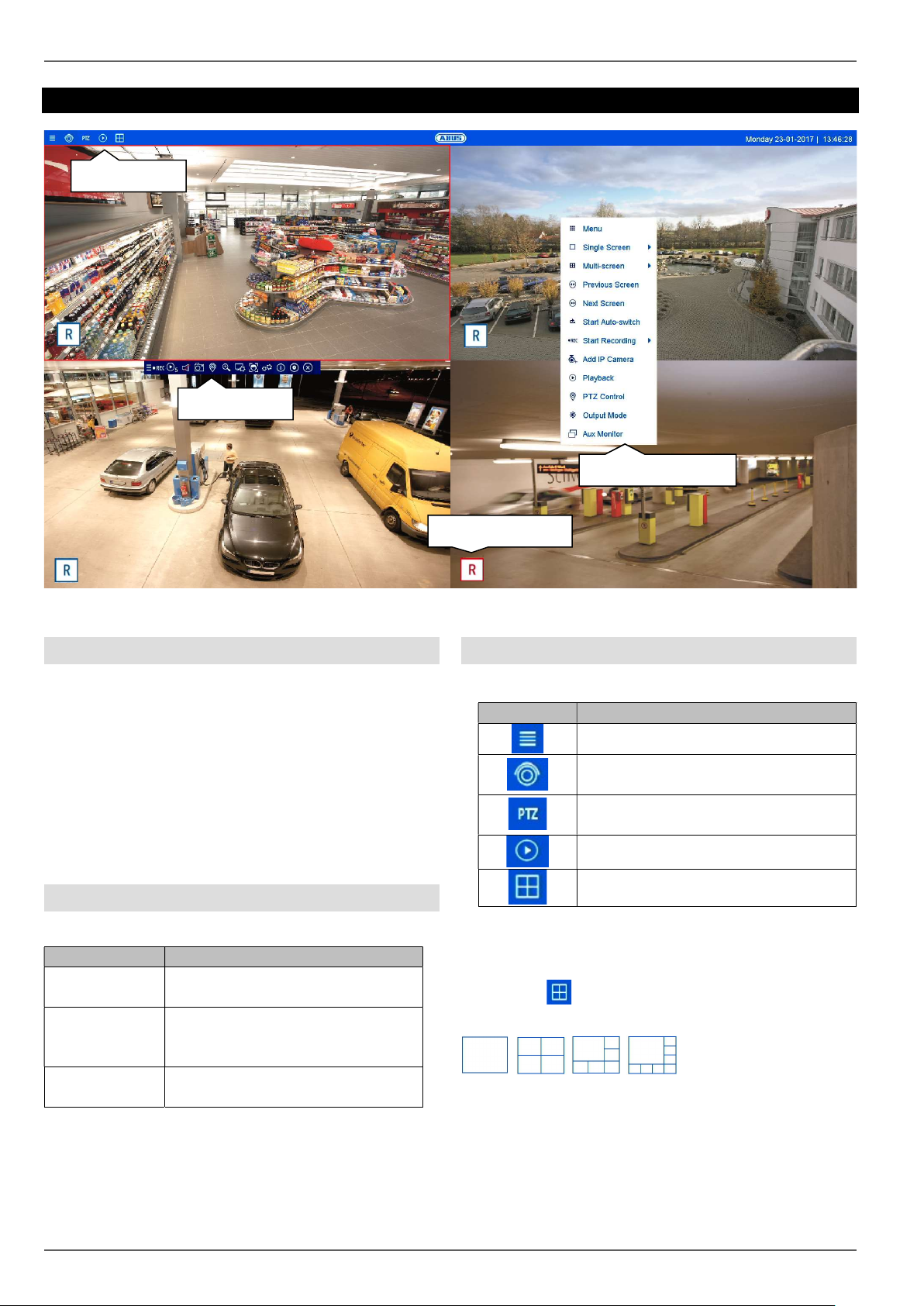
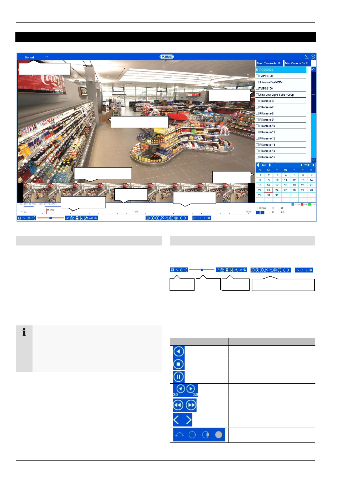
Live image function areas
The live view is divided into the following function areas:
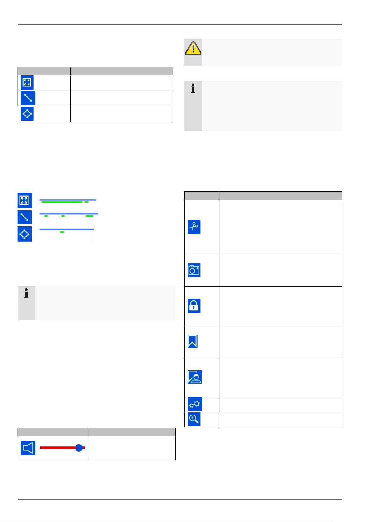
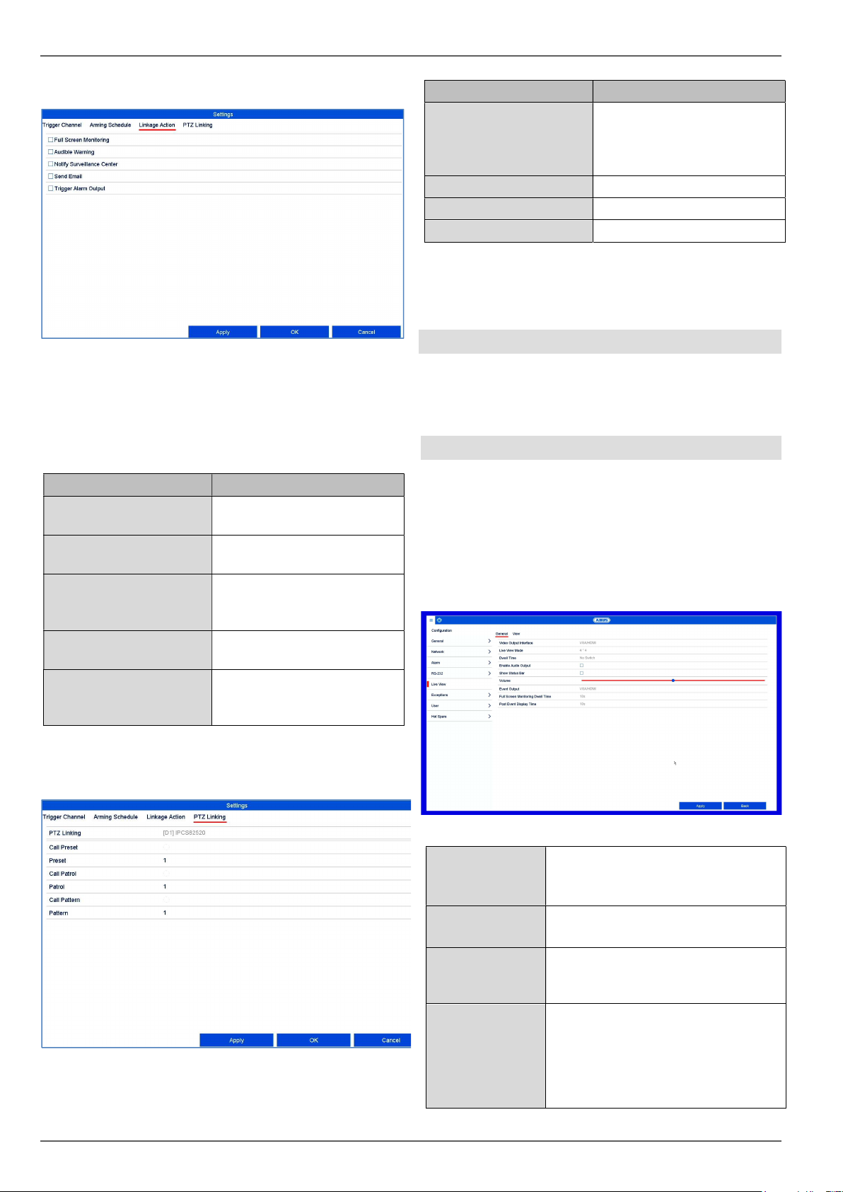
Menu bar operation
The following options are available:
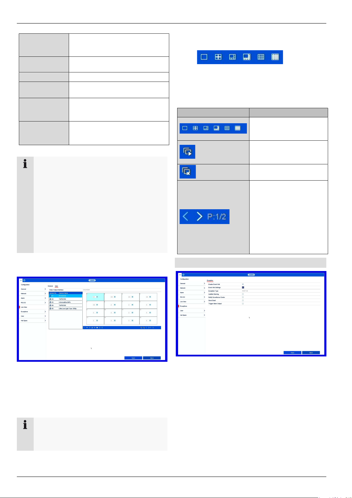
Multiview control
Click on the symbol to open multiview.
Various layouts are available:
Select a suitable layout the live view will be adjusted
accordingly. The settings which define the camera
positions can be individually programmed for each layout
in the configuration menu.
Parameter
Description
Menu bar
Global display of the configuration
and operating menus.
Action bar
Control of the camera commands
and actions for the selected
camera (red frame).
Right
-
click
menu
Extended operating menu for
operating the live view.
Parameter
Description
Opens the configuration menu
Activates the live image view
(deactivated in the live image)
Switch to the PTZ control menu (only
with PTZ cameras)
Switch to the playback view
Opens multiview
Action bar
Menu bar
Right-click menu
Recording status
Live view
21
Action bar operation
In single or multi-screen, click on a camera image. A
Gebruikershandleiding.com neemt misbruik van zijn services uitermate serieus. U kunt hieronder aangeven waarom deze vraag ongepast is. Wij controleren de vraag en zonodig wordt deze verwijderd.
Product:
Spelregels forum
Om tot zinvolle vragen te komen hanteren wij de volgende spelregels:
lees eerst de handleiding door;
controleer of uw vraag al eerder door iemand anders is gesteld;
probeer uw vraag zo duidelijk mogelijk te stellen;
heeft u een probleem en al geprobeerd om dit op te lossen, vermeld dit erbij aub;
heeft u een oplossing gekregen van een bezoeker dan horen wij dat graag in dit forum;
wilt u een reactie geven op een vraag of antwoord, gebruik dan niet dit formulier maar klik op de knop 'reageer op deze vraag';
uw vraag wordt direct op de website gezet; vermijd daarom persoonlijke gegevens in te vullen;
Belangrijk! Als er een antwoord wordt gegeven op uw vraag, dan is het voor de gever van het antwoord nuttig om te weten als u er wel (of niet) mee geholpen bent! Wij vragen u dus ook te reageren op een antwoord.
Belangrijk! Antwoorden worden ook per e-mail naar abonnees gestuurd. Laat uw emailadres achter op deze site, zodat u op de hoogte blijft. U krijgt dan ook andere vragen en antwoorden te zien.
Abonneren
Abonneer u voor het ontvangen van emails voor uw Abus nvr10020 bij:
nieuwe vragen en antwoorden
nieuwe handleidingen
U ontvangt een email met instructies om u voor één of beide opties in te schrijven.
Ontvang uw handleiding per email
Vul uw emailadres in en ontvang de handleiding van Abus nvr10020 in de taal/talen: Engels als bijlage per email.
De handleiding is 14,69 mb groot.
U ontvangt de handleiding per email binnen enkele minuten. Als u geen email heeft ontvangen, dan heeft u waarschijnlijk een verkeerd emailadres ingevuld of is uw mailbox te vol. Daarnaast kan het zijn dat uw internetprovider een maximum heeft aan de grootte per email. Omdat hier een handleiding wordt meegestuurd, kan het voorkomen dat de email groter is dan toegestaan bij uw provider.
Uw handleiding is per email verstuurd. Controleer uw email
Als u niet binnen een kwartier uw email met handleiding ontvangen heeft, kan het zijn dat u een verkeerd emailadres heeft ingevuld of dat uw emailprovider een maximum grootte per email heeft ingesteld die kleiner is dan de grootte van de handleiding.
Er is een email naar u verstuurd om uw inschrijving definitief te maken.
Controleer uw email en volg de aanwijzingen op om uw inschrijving definitief te maken
U heeft geen emailadres opgegeven
Als u de handleiding per email wilt ontvangen, vul dan een geldig emailadres in.
Uw vraag is op deze pagina toegevoegd
Wilt u een email ontvangen bij een antwoord en/of nieuwe vragen? Vul dan hier uw emailadres in.