677159
7
Verklein
Vergroot
Pagina terug
1/48
Pagina verder
Manual
CONTROL PROG
ENGLISH MANUAL
2
INTRODUCTION ............................................................................................... 4
NEWS AND IMPROVEMENTS ................................................................................ 4
GENERAL INFORMATION ABOUT CONTROL PROG ............................................... 4
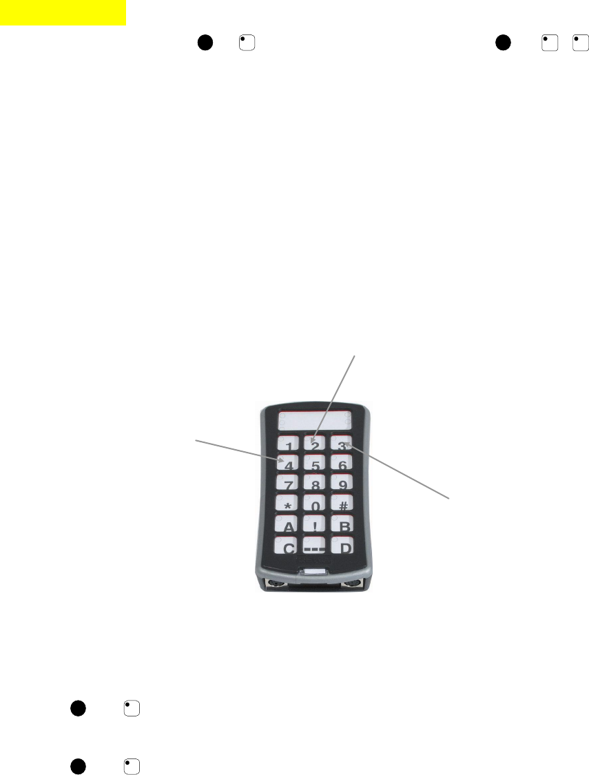
SYMBOLS ............................................................................................................ 6
INSERTING BATTERIES ........................................................................................ 6
BATTERY WARNING ............................................................................................ 6
SETTINGS ........................................................................................................... 7
CHOOSING LEVELS .............................................................................................. 7
REPLICATING CHANNELS FROM ANOTHER TRANSMITTER ................................... 9
LOCKING/UNLOCKING DELETE PROTECTION .................................................... 10
RESETTING CONTROL PROG TO FACTORY SETTING .......................................... 11
PROGRAMMING 4096 CODE .............................................................................. 12
COPYING CODES ............................................................................................... 14
SETTING BEEP VOLUME .................................................................................... 14
SWITCH ON/OFF ACOUSTIC LEVEL INDICATOR ................................................... 14
SETTING ACCEPTANCE DELAY .......................................................................... 15
CREATE AN AUTOMATIC SEQUENCE (MACRO) ................................................... 15
CREATE A MANUAL SEQUENCE .......................................................................... 16
DIRECT CHOICE OF LEVEL ................................................................................. 17
CREATE AUTOMATIC RETURN TO PRE-SET LEVEL .............................................. 18
SCANNING CONTROL .................................................................................. 19
CONNECTING CONTROL SWITCHES ................................................................... 19
QUICK CHOICE OF LEVEL AND ALARM ............................................................... 21
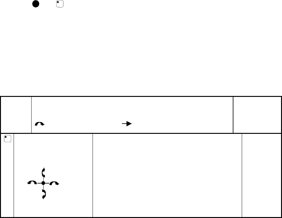
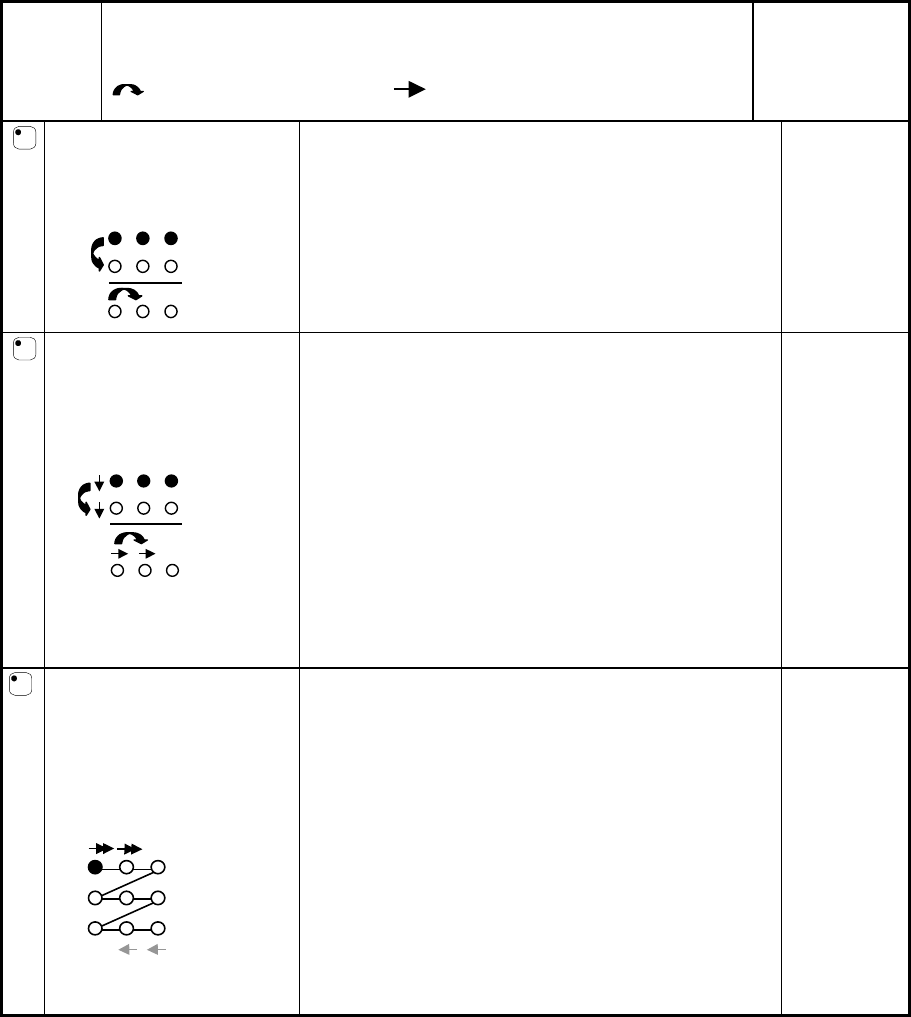
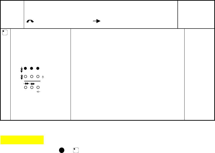
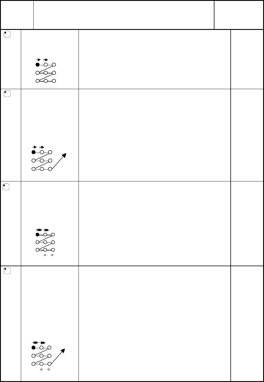
SETTING SCANNING METHOD ............................................................................. 21
CREATE AN INDIVIDUAL SCANNING SEQUENCE ................................................. 25
SETTING SCANNING SPEED................................................................................ 29
TURBO SCANNING ON/OFF ............................................................................... 29
SETTING OF SCANNING REPETITIONS ................................................................ 30
SETTING SCANNING START ............................................................................... 30
SCANNING BLINK ON/OFF .................................................................................. 31
OTHER CONTROL MATTERS .................................................................... 31
SCAN-SWITCH SHORTCUTS ................................................................................ 31
CREATE REMOTE SCANNING ............................................................................. 33
MOUSE SCANNING ............................................................................................. 35
OTHER COMPUTER CONTROL ............................................................................. 38
CONNECTION TO RELAY OUTPUT ...................................................................... 39
MISCELLANEOUS .......................................................................................... 39
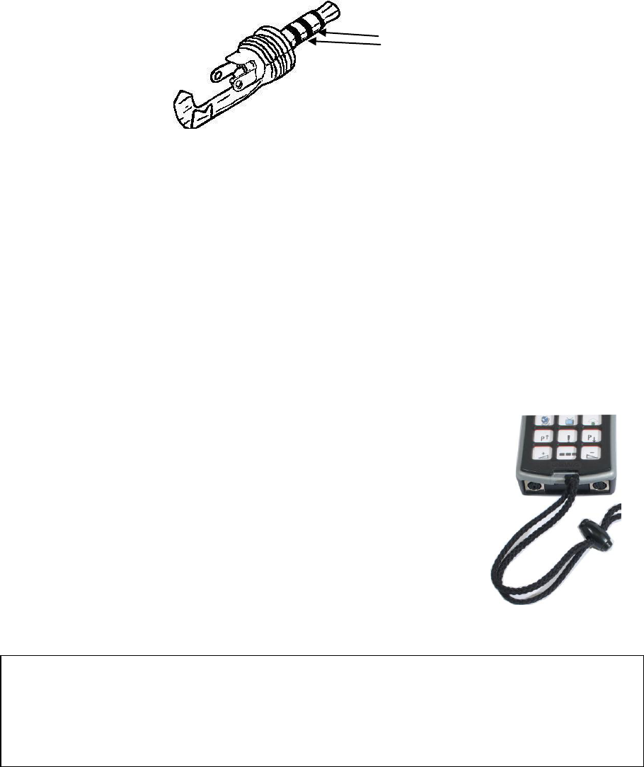
MOUNTING CONTROL PROG .............................................................................. 39
3
LABELLING ....................................................................................................... 40
DATA COMMUNICATION ................................................................................... 40
LOCKING FOR TRANSPORT ................................................................................. 41
CLEANING ......................................................................................................... 41
QUICK GUIDES .................................................................................................. 42
ACCESSORIES .................................................................................................... 45
TECHNICAL DATA ............................................................................................. 46
RECYCLING WASTE ELECTRICAL AND ELECTRONIC EQUIPMENT. ..................... 46
CONFORMITY WITH THE MEDICAL DEVICES DIRECTIVE ................................... 48
4
Introduction
Control Prog is a programmable IR-transmitter, which replaces ordinary remote
controls for TV, VCR and stereo sets. Control Prog has in all 241 different
programming positions and can be controlled by the integral keyboard or by
external control switches such as single- or multifunction switches (as well as
joysticks). When external control switches are used, different scanning options
can be chosen. The different functions can be controlled from a computer but it
is also possible to control functions on a computer from Control Prog.
News and Improvements
Control Prog has been further improved compared to earlier versions of Gewa
Prog III, which means that there will be new features available such as:
New design on casing
Rubber protection for inputs
Increased number of levels (5)
New functions to control a computer
Improved battery warning
Improved labelling of the keyboard
Location for level indication has been moved
Relay output changed
General Information about Control Prog
To be able to use Control Prog there are certain things you should know:
For programming, press the programming button using a pen, for example, at
the same time as you choose a function key. Different function keys are
chosen depending on what you want to program.
If you press the wrong key or if there is a programming mistake you can
always press the programming button on Control Prog. It works as a reset
button.
It is important not to wait too long between the different steps when
programming. After a certain time Control Prog automatically leaves the
programming mode to save power.
If a key on the keyboard or a scanning switch is pressed for more than 20
seconds, Control Prog will stop transmitting to save power.
5
The picture shows the various terms and functions which are described in the
text.
On delivery, Control Prog has the following settings:
Delay time is set to 0.
Sound volume is set to 4.
Only level 2 is open, other levels are closed.
Scanning starts from the top row.
Scanning speed is set to 1.5 seconds.
Scanning blink is activated
Scanning mode is set to alternative 6 (automatic linear scanning, 1 control
switch).
Maximum number of scanning repetitions is set to 2
GewaLink channels 00-127 are on level 1-8.
Inputs for 1 function
switches and outputs
for relay function
Indicator light when
programming
Function keys
0-9, !, *, #, A, B, C, D
Coded key
Computer terminal
Indicator lights
indicating different
levels:
Level 1-5 red
Level 6-10 green
Level 11-15 orange
Programming key
P
(reset)
Joystick terminal
Fig 1
Rubber protection
6
Functions for controlling a computer are placed on level 10
A random code on !-key.
Level indicator is switched off.
Symbols
The following symbols appear in the text:
P
= programming button
X
and
Y
= any key
Y
= any key on another transmitter to be programmed
0
9
*
#
= keys 0-9, * #
!
= coded key
---
= level key
---
= hold level key pressed for approximately 2 seconds
A
B
C
D
= keys A, B, C, D
Inserting Batteries
Unscrew the battery lid screw on the back of Control Prog using a screwdriver
and insert four alkaline LR03 (AAA) 1.5 V batteries. Insert the batteries
according to the marking at the bottom of the battery compartment. Pay
attention to the polarity! It is important to use long life alkaline batteries that are
protected against leaking battery acid. When you have inserted the new
batteries, press
P
Battery Warning
Control Prog has a built-in battery warning
indicating low battery voltage.
A sound signal with short beeps is heard at an interval of 30 seconds. After a
while it starts warning every ten minutes. Replace the batteries as soon as
possible.
7
Settings
Below is described how the different Control Prog functions are set.
Choosing Levels
Control Prog has altogether 15 levels with 16 programmable keys. On delivery
the keys are factory programmed with GewaLink channels 0-127, levels 1-8 (see
table 1). You can freely use one, several or all 15 levels. Five indicator lights
indicate the present level (see fig. 1). Levels 1-5 are indicated by red light, levels
6-10 by green light and level 11-15 are indicated by orange light. To be able to
distinguish the levels from each other they are also indicated by different beeps.
When several levels are active you change to another level by pressing the level
key
---
. Each time you press the key the next level is chosen. If the key is
continuously pressed, Control Prog scans through the levels until the key is
released. This is the case when Control Prog is factory programmed according to
scanning alternative 6. The exact behaviour of the level key depends on the
scanning method, manual or automatic scanning for instance. See under "Setting
of Scanning Alternatives".
Control Prog is delivered with only level 2 open other levels are closed. To
open further levels see under; “Opening/Closing a Level".
When only one level is open, the level key automatically contains one channel
which always is the first channel on the next level. In this way, it is possible to
control 18 functions even if only one level is open. See
1
in table 1.
8
Table 1 shows channels/codes for Control Prog on delivery.
Tabell 1
GewaLink channels
Key on
Control
Prog
Level 1-5
(red indicator)
Level 6-10
(green indicator)
Level 11-15
(orange
indicator)
1
2
3
4
5
6
7
8
9
10
11-15
1
00
16
32
48
64
80
96
112
62
Tab
62
2
1
17
33
49
65
81
97
113
62
62
3
2
18
34
50
66
82
98
114
62
Pg
up
62
4
3
19
35
51
67
83
99
115
62
62
5
4
20
36
52
68
84
100
116
62
Enter
62
6
5
21
37
53
69
85
101
117
62
62
7
6
22
38
54
70
86
102
118
62
Back
Space
62
8
7
23
39
55
71
87
103
119
62
62
9
8
24
40
56
72
88
104
120
62
Pg
Down
62
0
9
25
41
57
73
89
105
121
62
Win
62
*
10
26
42
58
74
90
106
122
62
Alt
F4
62
#
11
27
43
59
75
91
107
123
62
Alt
Tab
62
A
12
28
44
60
76
92
108
124
62
Alt
62
B
13
29
45
61
77
93
109
125
62
Esc
62
C
14
30
46
2
62
78
94
110
126
62
Space
62
D
15
31
47
63
79
95
111
127
62
F5
62
1….
16
32
48
64
80
96
112
62
62
62
00
!
Code
1
If only one level is open the level key automatically becomes one channel. It is
the first channel on the next level.
2
Channel 62 is a stop code and cannot control any function. On the other hand
you can store channels/codes on this key which in turn can control a function.
9
Opening/Closing a Level
1. Press
P
and
---
at the same time. The indicator light for the level key and the
current level are now lit.
2. Press
---
a number of times until you get to the level to be opened or closed.
3. Press
1
to open the chosen level or
2
to close the chosen level. The level
indicator light is automatically moved to the next level, which thereby
directly can be opened or closed.
4. Press
---
for approximately 2 seconds until the indicator light for the level
key flashes green and goes out.
It is possible to open level 1-10 at the same time by pressing
A
or open level 1-
15 by pressing
B
. Level 11-15 can only be opened by pressing
B
Quick guide
Open/close level:
P
+
---
, choose level,
1
or
2
……
---
Open =
1
. Close =
2
Open level 1-10 simultaneously:
P
+
---
,
A
,
Open level 1-15 simultaneously:
P
+
---
,
B
,
Factory setting = level 2 open.
Replicating Channels from another Transmitter
1. Make sure the batteries in both transmitters have full capacity.
Do not place the transmitters in intense light (e.g sunlight)
when programming.
2. Place the two transmitters on a table with the original
transmitter directed towards the rear of Control Prog (fig. 2).
3. Choose level which is to be programmed. Only one level at a
time can be programmed.
4. Press
P
and
1
at the same time. The indicator light on key 1
and chosen level now flashes.
To check that the transmitters are in the right position, keep any
key pressed on the original transmitter. The indicator light for
the level key now flashes green. Move the original transmitter
to the left or to the right until the indicator light goes out. Then
move the original transmitter backwards until the indicator light
goes out (one meter for certain transmitters). Place the original
transmitter between these positions. Certain types of
Fig 2
1
2
3
4
5
6
7
8
9
*
0
#
A
!
B
C
D
10
transmitters only emit a short flash each time the key is pressed. In these
cases, press several times.
5. Press and release the key on Control Prog that is to be programmed. The
indicator light for the level key now emits a steady orange light.
6. Press and hold the corresponding key on the original transmitter pressed.
Release the key when the indicator light for the level key gives a green light.
This might take up to 10 seconds. If the indicator light goes orange again
press the key one or more times until it flashes green and goes out. If the
indicator light flashes red the programming has failed. Try once more from
step 4. If a beep
is heard the level is locked and no programming can be
made. Read the next section how to unlock a level.
7. If the programming of the first key was successful, repeat steps 5 and 6 until
all keys are programmed. Finish by pressing
---
. The indicator light for the
level key flashes green to show that the programming is complete.
8. Now test the programmed functions on the device that is to be controlled.
Quick guide
Programming:
P
+
1
,
X
,
Y
, ….
---
Tip! Control Prog can record codes from most IR transmitters on the market
with a few exceptions. You may have problems with a few or all of the functions
for a certain IR transmitter. In these cases it is possible to try another recording
method. Instead, do as follows in step 4; Press
P
and
1
at the same time but
keep them pressed for approximately 2 seconds until the indicator light for the
level key flashes green and goes out. Control Prog is now in another recording
mode. Otherwise use the same recording procedure.
Locking/Unlocking Delete Protection
In order to protect codes from being deleted by accident when new codes are
programmed it is possible to lock each level separately. Locked level is
indicated by a beep
and no programming can be made. Do as follows to
lock/unlock levels:
1. Press
P
and
---
at the same time. The indicator light for the level key and the
current level are now lit.
2. Change to the level to be locked/unlocked by pressing
---
as many times as
needed.
3. Press
3
to lock or
4
to unlock. The indicator light for the levels is
automatically moved to the next level, which thereby can be locked/unlocked
immediately.
11
4. Press
---
for approximately 2 seconds until the indicator light for the level
key flashes green and goes out.
Quick guide
Lock/unlock delete protection
P
+
---
, choose level,
3
or
4
,….
---
,
Lock level =
3
. Unlock level =
4
.
Resetting Control Prog to Factory Setting
Control Prog makes it possible to erase what is stored for a single key, for all
keys for a single level or for all keys for all levels (1-15) at the same time. The
GewaLink channels 00-127 (factory setting) replace the erased channels. Table
2 shows what happens when resetting Control Prog. Also read under
"Locking/Unlocking Delete Protection".
Table 2
Resetting one
key
The level used for the key must be unlocked before erasure.
Resetting one
level
The corresponding level must be unlocked before erasure.
Resetting all
levels
Levels 1-15 are erased and returned to factory setting even
if these levels are locked.
Other settings are also returned to factory setting and a new
random code is programmed on the !-key.
1. Start by unlocking the level to be reset. This is not necessary if all levels are
to be reset at the same time.
2. Using the level key choose the level for which you want to perform the reset
operation. This will not be necessary if all levels are to be reset at the same
time.
3. Press
P
and
3
at the same time. The indicator light on key 3 and chosen
level are now lit.
4a. Resetting a single key:
Press the key to be reset. The indicator light for the level key flashes green
to show that the operation is complete.
4b. Resetting all keys for a single level:
Press in turn the keys
---
,
1
,
2
,
3
and finish with
---
.
All keys flash red in turn. The indicator light for the level key flashes green
to show that the operation is complete.
12
4c. Resetting all keys for all levels:
Press in turn the keys
!
,
1
,
2
,
3
and finish with
---
.
All keys on levels 1-15 flash red in turn. The indicator light for the level key
flashes green to show that the operation is complete.
Quick guide
Resetting a single key
X
:
Choose level,
P
+
3
, choose key
Resetting all keys for a single level:
Choose level,
P
+
3
,
---
,
1
,
2
,
3
,
---
Resetting all levels to factory setting:
P
+
3
,
!
,
1
,
2
,
3
,
---
Programming 4096 Code
Control Prog is delivered with a special coded channel (4096) on the !-key. The
code is selected at random. This coded channel is normally used for functions
that require strict authorisation such as apartment doors or house doors. The
code has 4096 different combinations. The !-key always has the same code
irrespective of which level you use. If you have to program a new coded channel
there are three methods of doing so.
Method one: Use a coded transmitter as described under “Replicating channels
from another transmitter”. Using this method you can program any key to use a
coded channel.
Method two: Enter a numerical value between 0 and 4095. The indicated code
will always be associated with the !-key. It is then possible to move the code
from this key to other keys (See under “Copying Codes”). Then you can create a
new coded channel if you wish. Do as follows:
1. Press
P
and
!
at the same time. The indicator light on !-key and the current
level are now lit.
2. Enter a number from 0 to 4095.
3. Finish with
---
. The indicator light for the level key flashes green to show that
the operation is complete. Make a note of the chosen code for future usage.
13
Quick guide
Setting a 4096 code:
P
+
!
,
0
4
0
9
5
,
---
Factory setting = random code.
For method three insert a binary code. The binary code will always be
associated with the !-key. Make up the binary code yourself or else use a code
that is already set in an IR receiver or IR transmitter.
There are two types of IR receivers: an older type of receiver where you set the
code with a 12-pole switch or a newer type where the IR receiver is
programmable. The principle is the same when it comes to creating the binary
code. Figure 3 shows a 12-pole switch. Switches 1, 4, 6 and 12 are in the On
position, the others are in the Off position.
The following example describes how the binary code is created according to
figure 3:
1. Press
P
and
!
at the same time. The indicator light on !-key and the current
level are now lit.
2. Enter the code by pressing
!
or
---
.
!
= switch in the On position and
---
=
switch in the Off position. Press twelve times in turn;
!
,
---
,
---
,
!
,
---
,
!
,
---
,
---
,
---
,
---
,
---
,
!
. The indicator light for the level key flashes green to show
that the operation is complete. The code is now on the
!
-key. Make a note of
the chosen code for future usage.
Quick guide
Setting 4096 code binary:
P
+
!
, ……
On position =
!
. Off position =
---
Factory setting = random code.
1 2 3 4 5 6 7 8 9 10 11 12
2048 1024 512 256 128 64 32 16 8 4 2 1
On
Off
Fig. 3
14
Copying Codes
Control Prog makes it possible to copy programmed codes and basic channels to
other places (keys). Note! The code/channel remains in its original place.
1. Choose level and press the key from which the code is to be copied.
2. Choose the level to which you want to copy the code.
3. Press
P
and
8
at the same time. The indicator light on key 8 and the current
level are now lit.
4. Press the key to which you want to copy the code. The indicator light for the
level key flashes green to show that the operation is complete.
Quick guide
Copying code/channel from key
X
to key
Y
:
Choose level, choose
X
, choose level,
P
+
8
, choose
Y
Setting Beep Volume
Control Prog has a beep signal, which sounds when a key is pressed or when
scanning. Set the beep volume between 0 and 9. 0 is no sound at all and 9 is
maximum sound level.
1. Press
P
and
4
at the same time. The indicator light on key 4 and the current
level are now lit.
2. Press a key from
0
-
9
to choose beep volume. The indicator light for the
level key flashes green to show that the operation is complete.
Quick guide
Setting beep volume:
P
+
4
,
0
….
9
Factory setting = 4.
Switch on/off acoustic level indicator
To indicate the current level it is possible to activate an acoustic level indicator.
When the !-key is pressed the current level is indicated by a series of beeps. This
also applies for the first step when scanning.
Levels 1-5 are indicated by 1-5 short tone burst at a high pitch, level 6-10 by 1-5
short tone bursts at a low pitch and levels 11-15 are indicated by 1-5 short tone
bursts at even an lower pitch.
Do as follows to switch on/off the level indicator:
15
1. Press
P
and
4
at the same time. The indicator light on key 4 and the current
level are now lit.
2. Press
*
to switch on or press
#
to switch off. The indicator light for the
level key flashes green to show that the operation is complete.
Quick guide
Switch on level indicator:
P
+
4
,
*
Switch off level indicator:
P
+
4
,
#
Factory setting = Off
Setting Acceptance Delay
An acceptance delay can be set for keys and control switches. The acceptance
delay is the time a key has to be pressed before a function is activated. The
acceptance delay can be set from 0 to 9. 0 is no delay at all and 9 is the
maximum delay (0.9 sec.).
1. Press
P
and
2
, at the same time. The indicator light on key 2 and the
current level are now lit.
2. Press a key from 0-9 to choose the delay time. The indicator light for the
level key flashes green to show that the operation is complete.
Quick guide
Setting Acceptance Delay:
P
+
2
,
0
….
9
Factory setting = 0.
Create an automatic sequence (Macro)
Control Prog is able to send sequences of codes. When you press one key
Control Prog automatically carries out what is equivalent to pressing several
keys. To find a teletext page for instance you need to press four keys. Control
Prog however, can be programmed in such a way that you only need to press
one key. Other available applications are dialling long telephone numbers or
muting the TV at the same time as you answer the telephone. Control Prog can
also be programmed to change levels and remember how long a key should
transmit (max. 25.5 sec). Other programmed sequences can also be a part of a
new sequence.
A sequence can be terminated at any time by pressing any other key. When a
sequence is programmed Control Prog transmits at the same time what is already
16
on the key. A maximum of 47 key presses per sequence can be programmed.
NOTE! The key used for the sequence must not be part of the sequence.
1. Press
P
and
A
at the same time.
2. Press the keys that should be used for the sequence.
3. Choose the level where you want the sequence to be.
4. Press
P
and
B
at the same time. The indicator light on key B and the current
level are now lit.
5. Choose the key where you want the sequence to be. The indicator light for
the level key flashes green to show that the operation is complete.
Quick guide
Create an automatic sequence:
P
+
A
, press sequence, choose level,
P
+
B
,
choose where to store the sequence.
Create a manual sequence
A manual sequence is a variant of an automatic sequence. Such a sequence is
advanced manually one step at a time while an automatic sequence is
automatically transmitted as a whole. When the manual sequence has reached
the end, it will start from the beginning again. Even if you press other keys in-
between, Control Prog will always remember the latest step of the sequence.
You can, for instance, turn the TV on and off using only one key. You can also
create a very simple scanning method stepping through different TV channels.
A sequence can consist of a series of key presses from different levels and can
also remember the duration of the transmission of a key (max 25.5 seconds).
When a sequence is created Control Prog at the same time transmits what is
stored on the key. A maximum of 47 key pressures per sequence can be
programmed. NOTE! The key used for the sequence must not be a part of the
sequence.
Do as follows to create a manual sequence;
1. Press
P
and
A
at the same time.
2. Press the keys that will be part of the sequence. Also change of level.
3. Choose level for the sequence.
4. Press
P
and
C
at the same time. The indicator light on key C and the current
level are now lit.
5. Press
B
..
6. Choose key for the sequence. The indicator light for the level key flashes
green to show that the operation is complete.
17
Quick guide
Create manual sequence:
P
+
A
, press sequence, choose level,
P
+
C
,
B
,
where to store the sequence.
Direct choice of level
Control Prog makes it possible to create direct access keys which mean that you
can reach a level by pressing a selected key. If you are at level 1 for instance and
press key 2 you will directly reach level 2. By pressing key 3 you will directly
reach level 3 etc. When you are at level 2, 3 or 4 you can press a new direct
access key to return to level 1. You need to create the direct access keys for
these levels in advance. See fig. 4.
Do as follows to create direct access keys:
1. Choose the level you want to reach with a direct access key.
2. Press
P
and
A
at the same time.
3. Choose the level where the direct access key is to be stored.
4. Press
P
and
B
at the same time. The indicator light on key B and the current
level are now lit.
5. Choose and press the key, which is to be the direct access key. The indicator
light for the level key flashes green to show that the direct access key is
stored.
Press key 2 and you will
directly get to level 2.
Fig 4
Press key 2 and you
will directly get to
level 3.
Press key 4 and you
will directly get to
level 4.
It is also possible to create
a direct access key in
level 2, 3 and 4 to return
to level 1.
Level 1
18
Quick guide
Create a direct access key:
Choose level to be reached through direct choice,
P
+
A
, choose level where a
direct access key is to be stored,
P
+
B
, choose the key which is to be a direct
access key.
Create automatic return to pre-set level
Control Prog can be set to always return to a special pre-set level when several
levels are open. This pre-set level can for instance be functions for making
telephone calls, or other functions you use often and want to reach quickly.
After approximately 5 minutes Control Prog returns to the pre-set level. Do as
follows to turn on/off automatic return to pre-set level:
1. Press
P
and
---
at the same time. The indicator light for the level key and the
current level are now lit.
2. Choose return level for Control Prog.
3. For automatic return press
5
and press
6
to switch off. The indicator light
for the level key flashes green to show that the operation is complete.
Quick guide
Turn on/off automatic return:
P
+
---
,
5
or
6
Turn on =
5
. Turn off =
6
.
Factory setting = turned off
19
Scanning Control
It is possible to connect external scanning control switches to enable control of
241 functions via a single switch. Settings can be programmed such as different
scanning methods, scanning speed, scanning start, number of scanning
repetitions, turbo scanning and scanning blink. It is even possible to create an
individual scanning method. 1-5 control switches or joystick can be connected
depending on scanning method. Read the section below for a description.
Connecting Control Switches
There are several ways of connecting control switches depending on the number
of switches that will be needed. It is possible to connect one or two 1-function
control switches to Sw 1 and Sw 2. At input Multi you can connect control
switches for all four directions and Enter. It is possible to control 8 directions
and Enter with a Joystick.
1 control switch: Input Sw 1, Sw 2 or Multi. All terminals can be used when
only one control switch is used.
2 control switches: Input Sw 1 () and Sw 2 ().
3 control switches: Input Sw 1 (), Sw 2 () and Multi (Enter).
Alternatively all three control switches can be connected to Multi.
5 control switches: Input Multi (, , , and Enter).
Enter: Execute by pressing the control switch connected to Multi (Enter).
You can also execute by using Sw 1 or Sw 2 depending on what scanning
method you have chosen. See table 4!
Joystick with 8 directions + Enter: Input Multi.
20
Table 3
Number
of
functions
Direction with
joystick
Soldering points on 6-
pole mini Din-contact
1
1, 3
2
1, 4
3
1, 2
4
1, 5
5
Enter
1, 6
6
+ gives
1, 3, 4
7
+ gives
1, 2, 4
8
+ gives
1, 2, 5
9
+ gives
1, 3, 5
1
2
3
4
5
6
7
8
1
2
3
4
5
6
Com
Enter
Fig 6
Terminal for control
switches and outputs
for relay function, 3.5
mm phone plug
Data connection
8-pole mini DIN
outlet
Terminal for multiple
function control switch,
joystick e.g., 6-pole
mini DIN outlet
Data
Sw 2
Sw 1
Multi
5
1
2
6
7
9
4
3
8
Fig. 5
Functions 1-5 can be replaced with singel control
switches.
21
Quick choice of level and alarm
When scanning with an external control switch it is possible to change levels
quickly. By holding the control switch pressed when starting scanning. Control
Prog will change over to stepping between different levels. This is a quick way
of being able to choose level. Note! At least two levels must be open.
If the control switch is held pressed for longer time, Control Prog will control
the coded key. If a relay adapter, which is connected to an alarm transmitter is
connected, it is possible to call for help. The control switch only needs to be
pressed until the alarm is activated. See further sections on the connection of
relay adapters.
Setting scanning method
Control Prog has 12 different scanning methods. The differences between the
various alternatives are described in table 4. Do as follows to choose the
scanning method:
1. Press
P
and
5
at the same time. The indicator light on key 5 and the current
level are now lit.
2. Choose scanning method according to table 4 and press the corresponding
key. The indicator light for the level key flashes green to show that the
operation is complete.
Table 4
Setting
Scanning method
= manual scanning. = automatic scanning
Number of
control
switches
0
Manual scanning in
four directions.
Press once for each step in any direction.
Execute by pressing Enter button.
3 to 5
&
joystick
22
Table 4
Setting
Scanning method
= manual scanning. = automatic scanning
Number of
control
switches
1
Manual repeating
scanning in four
directions.
Press once for each step in any direction.
If the control switch is pressed
continuously Control Prog scans
automatically in the chosen direction.
Execute by pressing the Enter button.
3 to 5
&
joystick
2
Manual scanning in
four directions.
Change of levels at
the beginning of and
at the end of each
line.
Press once for each step in any direction.
If scanning continues at the end of the
line, Control Prog automatically changes
levels. Execute by pressing the Enter
button.
3 to 5
&
joystick
3
Manual scanning in
four directions with
repetition and change
of levels at the
beginning of and at
the end of each line.
Press once for each step in any direction.
If the control switch is pressed
continuously Control Prog scans
automatically in the chosen direction. If
scanning continues at the end of the line,
Control Prog automatically changes
levels. Execute by pressing the Enter
button.
3 to 5
&
joystick
23
Table 4
Setting
Scanning method
= manual scanning. = automatic scanning
Number of
control
switches
4
Manual linear
scanning.
Press (Sw 1) once for each step in
numerical order 1, 2, 3…
Execute using Sw 2.
2
5
Repeated manual
linear scanning.
Press (Sw 1) once for each step in
numerical order, 1, 2, 3... If the control
switch is pressed continuously Control
Prog scans automatically. Execute using
Sw 2.
2
6
Automatic linear
scanning.
Press the Sw 1 or Sw 2 key to start the
scanning. Control Prog then
automatically starts scanning in
numerical order 1, 2, 3… Press again to
execute.
1
7
Automatic row and
column scanning.
Press the Sw 1 or Sw 2 key to start the
scanning. Control Prog then
automatically starts scanning vertically.
Press once more and Control Prog scans
horizontally. Press a third time to
execute.
1
24
Table 4
Setting
Scanning method
= manual scanning. = automatic scanning
Number of
control
switches
8
Manual row and
column scanning.
Start scanning vertically by pressing the
Sw 2 key. Press the Sw 1 key to scan
horizontally. Execute by pressing the
first control switch once again. It is also
possible to execute by pressing a special
control switch (Enter).
2 to 5
9
Automatic and
manual row/column
scanning.
Start scanning vertically by pressing the
Sw 2 key. Press the Sw 1 key to scan
horizontally. Scanning is automatic but
you can speed it up by pressing a control
switch in the same direction as that of the
scanning (or one in the opposite
direction). Execute by pressing the first
control switch once again. It is also
possible to confirm by pressing a special
control switch (Enter).
2 to 5
*
Automatic linear
scanning with
reverse scan
(overscan).
Press the Sw 1 or Sw 2 key once to start
numeric, automatic scanning, 1, 2, 3…
Press the key a second time and the
scanning stops, then continues slowly
backwards. Execute by pressing a third
time. NOTE! Control Prog starts at 4
times higher speed but then reverses with
the set speed.
1
25
Table 4
Setting
Scanning method
= manual scanning. = automatic scanning
Number of
control
switches
#
Automatic line and
column scanning
with reverse scan
(overscan).
Press the Sw 1 or Sw 2 key once to start
automatic scanning vertically. Press the
key a second time and the scanning stops
then continues slowly backwards
vertically. Press a third time to start
horizontal scanning. Press the key a
fourth time and the scanning stops then
continues slowly backwards. Execute by
pressing the key a fifth time. NOTE!
Control Prog starts at 4 times higher
speed but then reverses with the set
speed.
1
Quick guide
Set scanning method:
P
+
5
, choose scanning method.
Factory setting = Scanning method 6.
Create an individual scanning sequence
With Control Prog it is possible to create an individual scanning sequence which
can be stored on any key, for instance to make it possible to scan to keys which
only have functions for different TV channels or channels to dial individual
telephone numbers. It is also possible to change between different levels in the
scanning sequence. On creation of a scanning sequence the scanning method is
chosen according to table 5 which is applicable for individual scanning
sequences only. Other scanning sequences may contain other scanning methods.
The scanning method, which is normally used according to table 4, is not
affected. A sequence may consist of a maximum of 96 steps. NOTE! The key on
which the sequence is stored must not be a part of the sequence.
26
Table 5
Setting
Scanning method
Only for individual scanning sequences
Number of
control
switches
0
Manual linear
scanning.
Move to the key where a scanning sequence
is stored and activate it. Then scan by
pressing the key (Sw 1) once for each step in
the same order as when the sequence was
created. Execute using Sw 2 or Enter.
2 to 3
1
Manual linear
scanning
followed by
normal
scanning.
Move to the key where a scanning sequence
is stored and activate it. Then scan by
pressing the key (Sw 1) once for each step in
the same order as when the sequence was
created. Execute using Sw 2 or Enter.
Otherwise normal scanning follows.
2 to 3
2
Repeated
manual linear
scanning.
Move to the key where a scanning sequence
is stored and activate it. Then scan by
pressing the key (Sw 1) once for each step in
the same order as when the sequence was
created. If the control switch is pressed
continuously Control Prog scans
automatically. Execute using Sw 2 or Enter.
2 to 3
3
Repeated
manual linear
scanning
followed by
normal
scanning.
Move to the key where a scanning sequence
is stored and activate it. Then scan by
pressing the key (Sw 1) once for each step in
the same order as when the sequence was
created. If the control switch is pressed
continuously Control Prog scans
automatically. Execute using Sw 2 or Enter.
Otherwise normal scanning follows.
2 to 3
27
Table 5
Setting
Scanning method
Only for individual scanning sequences
Number of
control
switches
4
Automatic
linear scanning.
Move to the key where a scanning sequence
is stored and activate it. Control Prog will
start automatic scanning in the order the
sequence was created. Execute by pressing
the Sw 1 or Sw 2 key once more.
1
5
Automatic
linear scanning
followed by
normal
scanning.
Move to the key where a scanning sequence
is stored and activate it. Control Prog will
start automatic scanning in the order the
sequence was created. Execute by pressing
the Sw 1 or Sw 2 key once more. Otherwise
normal scanning follows.
1
6
Automatic
linear scanning
with reverse
scan (overscan).
Move to the key where a scanning sequence
is stored and activate it. Control Prog will
start automatic scanning in the order the
sequence was created. Press again and the
scanning stops and then reverses slowly.
Execute by pressing the Sw 1 or Sw 2 key
once more. NOTE! Control Prog starts
scanning at 4 times the normal speed but
then reverses with the set speed.
1
7
Automatic
linear scanning
with reverse
scan (overscan)
followed by
normal
scanning.
Move to the key where a scanning sequence
is stored and activate it. Control Prog will
scan automatic in the order the sequence was
created. Press again and the scanning stops
and then reverses slowly. Execute by
pressing the Sw 1 or Sw 2 key once more.
Otherwise normal scanning follows. NOTE!
Control Prog starts scanning at 4 times the
normal speed but then reverses with the set
speed.
1
28
Do as follows to create an individual scanning sequence:
1. Press
P
and
*
at the same time. The indicator light on key * and the current
level are now lit.
2. Press
1
.
3. Press the key on which the sequence is to be saved.
4. Choose the scanning method according to table 5.
5. Press the keys that are part of the sequence.
6. Finish by holding key
---
pressed (approximately 2 seconds) until the
indicator light for the level key flashes green and goes out.
Quick guide
Create an individual scanning sequence:
P
+
*
,
1
, choose where to store the
sequence, choose scanning method, press sequence,
---
.
Tip 1: It is possible to combine an individual scanning sequence with direct
control, e.g. to make Control Prog always start scanning using an individual
scanning sequence. The individual scanning sequence can then contain
important functions. It can for instance be used to trigger an alarm, open a
telephone line, answer a hall telephone and open a door. If no choice is made for
these functions, Control Prog continues with normal scanning. Scanning method
1, 3 or 5 must then be set.
Do as follows to create this combination:
Create a key with an individual scanning sequence. Choose one of the scanning
methods 1, 3 or 5 in this sequence. Then program the same key with direct
control. Change the number of scanning repetitions to 1. Control Prog will now
start the scanning, first by stepping through the sequence, and if no choice has
been made in the sequence, Control Prog continues with normal scanning.
Tip 2: It is also possible to make Control Prog only scan the left column and
nothing more. The middle and the right column can then be used for marking of
each function.
Do as follows to create this.
Create a key with an individual scanning sequence that consists of the left
column. NOTE! The key on which the sequence is to be saved must not be a
part of the sequence. Choose one of the scanning methods 0, 2, 4 or 6 in this
29
sequence. Then program direct control on the same key. Control Prog will now
only step through the left column.
Setting Scanning Speed
The scanning speed can be programmed from 0.1 to 6.0 seconds in 0.1 second
steps. The scanning speed is set to 1.5 seconds on default. Do as follows to
program the scanning speed:
1. Press
P
and
6
at the same time. The indicator light on key 6 and the
current level are now lit.
2. Choose the speed. General rule: The speed you want, 0.7 seconds for
instance, is multiplied by 10, and the result is the key/keys to be used.
Example: 0.7 x 10 = 7. Consequently you press key 7 to get the scanning
speed 0.7 seconds. For the highest speed 0.1 seconds you press 1. For the
lowest speed 6 seconds you press 60.
3. Finish by pressing
---
. The indicator light for the level key flashes green to
show that the operation is complete.
Quick guide
Setting scanning speed:
P
+
6
,
1
….
6
0
,
---
Factory setting = 1.5 seconds.
Turbo Scanning On/Off
Turbo scanning can be used to speed up the scanning speed four times. This
setting is intended for advanced users with advanced requirements. Turbo
scanning always starts out from the chosen scanning speed but then the time is
divided by a factor 4. This results in a more precise setting especially within the
interval 0.1-1.0 seconds, e.g. 0.5 seconds divided by 4 gives 0.125 seconds. The
scanning indicator light stops flashing which makes it easier to observe at these
high speeds. Do as follows to turn turbo scanning on/off:
1. Press
P
and
6
at the same time. The indicator light on key 6 and the current
level are now lit.
2. To turn turbo scanning on press
A
and to turn it off press
B
. The indicator
light for the level key flashes green to show that the operation is complete.
Quick guide
Turbo scanning on/off:
P
+
6
,
A
or
B
Turn on =
A
. Turn off =
B
.
Factory setting = Off
30
Setting of Scanning Repetitions
It is possible to decide the number of repetitions that Control Prog shall carry
through on scanning. From the moment the scanning has been started and until
the scanning has returned to the starting point is one repetition if nothing is
executed. It is possible to choose between 1 - 4 repetitions. Do as follows to set
the number of repetitions:
1. Press
P
and
7
at the same time. The indicator light on key 7 and the current
level are now lit.
2. Press
#
.
3. Choose the number of repetitions 1 - 4. The indicator light for the level key
flashes green to show that the operation is complete.
Quick guide
Setting of scanning repetitions:
P
+
7
,
#
,
1
….
4
Factory setting = 2 repetitions.
Setting Scanning Start
You can choose where you want Control Prog to start the scanning, line 1 - line
6 or the level key. Line 1= key 1, 2, 3, line 2= key 4, 5, 6 etc. If key 0 is chosen
the level key starts the scanning. One advantage of starting the scanning using
the level key is that you will get more quickly to a specific key. Default setting
for Control Prog is to start scanning on line 1.
Do as follows to set the scanning start:
1. Press
P
and
7
at the same time. The indicator light on key 7 and the current
level are now lit.
2. Choose a line by pressing one of the keys 0-6. The indicator light for the
level key flashes green to show that the operation is complete.
Quick guide
Setting scanning start:
P
+
7
,
0
….
6
Factory setting = Line 1
31
Scanning blink on/off
For each time Control Prog advances one step when scanning the light flashes a
number of times. For certain users flashing light can be irritating and confusing.
It is then possible to turn it off and have a fixed light. The drawback is that the
power consumption of Control Prog thereby increases 40 %. Do as follows to
turn the flashing on/off:
1. Press
P
and
6
at the same time. The indicator light on key 6 and the current
level are now lit.
2. Press
*
to turn on or
#
to turn off. The indicator light for the level key
flashes green to show that the operation is complete.
Quick guide
Turn flashing on/off:
P
+
6
,
*
or
#
Turn on =
*
. Turn off =
#
.
Factory setting = Flashing activated.
Other Control Matters
Scan-switch shortcuts
Control Prog makes it possible to directly control functions using external
control switches, e.g. key 1 on Control Prog is controlled by an external control
switch, key 2 is controlled by the next external control switch, etc. A maximum
of 9 functions can be controlled in this way. However, to be able to use more
than 5 functions a joystick must be used. You can add 9 functions for each level.
On the other hand, it is not possible to choose level with external control
switches. It is only possible to choose a certain level by using the level key
directly.
When scan-switch shortcuts are entered, choose where the first function is to be
stored; other functions are automatically stored in sequence (table 3). It is
possible to limit the number of functions to be used by storing them on one of
the 8 last keys. If for instance a scan-switch shortcut is stored on key D, only
this key is activated independently of the number of connected control switches
or the direction in which the joystick is moved. If, on the other hand, scan-
switch shortcuts are stored on key B for example, "right" will activate key B,
"down" will activate key C and all other directions will activate key D. In this
example, a joystick does not necessarily have to be used. Three control switches
32
can represent the different directions. In the table below you can see how the
joystick should be moved to activate different keys depending on where the
scan-switch shortcuts are stored. To connect external control switches or a
joystick, see section; Connection of control switches.
Table 6
Keys activated depending on the chosen storage space
Storage-
space
Number of
functions
8
9
0
*
#
A
B
C
D
8
9 functions
(maximum)
Enter
9
8 functions
Enter
,
0
7 functions
Enter
, ,
*
6 functions
Enter
, , ,
#
5 functions
Enter, , , ,
A
4 functions
, Enter, , ,
,
B
3 functions
, , Enter, ,
, ,
C
2 functions
, , , Enter,
, , ,
D
1 function
, , , ,
Enter, , ,
,
Tip: It is possible to combine direct control with an individual scanning
sequence. Read this section too!
To create/erase direct control, do as follows:
1. Press
P
and
*
at the same time. The indicator light on key * and the current
level are now lit.
2. Press
0
.
3. Choose level and press the key on which the first function is to be stored. The
indicator light for the level key flashes green to show that the operation is
complete.
Other functions are automatically stored in sequence according to table 3 and
33
figure 5.
If a scan-switch shortcut is to be erased instead hold
---
pressed
(approximately 2 seconds) until the indicator light for the level key goes out.
Quick guide
Create a scan-switch shortcut:
P
+
*
,
0
, choose level, choose where to store
the shortcut.
Erase a scan-switch shortcut:
P
+
*
,
0
, choose level,
---
.
Create Remote Scanning
It can sometimes be difficult to control functions that require rapid change of
channels or repeatedly transmit the same channel during a short time and at the
same time use scanning as e.g. as needed to control the functions of a page-
turner. Using Control Prog with normal scanning this is rather difficult. If on the
other hand Remote Scanning is chosen it is easy to control page-turners or
similar applications. Remote Scanning can always be stored on any key. When
you activate this key, either by pressing the key or by scanning to this key, it is
possible to directly control the keys 1-9 using the joystick or external control
switches. You can remain in this position as long as you wish. On the level
where Remote scan is stored it‟s always keys 1-9 that are activated. A maximum
of 9 functions can be controlled in this way. To control more than 5 functions a
joystick is required. Table 7 shows the keys that are activated depending on in
what direction a joystick is moved. It is always possible to replicate new
channels/codes on these keys. The indicator lights on key 1-9 flash when a
joystick is moved in different directions. Also, see section "Connection of
control switches".
Table 7
Number of
functions
Joystick
direction
Key that is
activated
1
6
2
8
3
4
4
2
5
Enter
5
6
9
7
7
8
1
9
3
Functions 1-5 can be replaced by one
function control switches.
34
There are two different settings for Control Prog when Remote Scanning is set;
dwell time, and time out.
Dwell time: The time required to leave Remote Scanning (1-25 sec.,
recommended setting 5 sec.). If you keep a control switch pressed or the joystick
is constantly displaced in any direction during the dwell time then Control Prog
leaves Remote Scanning.
Time out: The time needed for Control Prog to leave Remote Scanning
automatically (1-255 sec, recommended setting 240 sec).
There are two different ways of creating Remote Scanning:
Automatic setting of dwell time (5 sec) and time out (240 sec).
Manual setting of dwell time and time out.
Do as follows to create Remote Scanning Control with automatic setting:
1. Press
P
and
*
at the same time. The indicator light on key * and the current
level are now lit.
2. Press
2
.
3. Choose level and press the key where the function is to be stored.
4. Finish by pressing
---
. The indicator light for the level key flashes green to
show that the operation is complete.
Now test by scanning to the key or pressing the key where Remote Scanning
is stored. If a joystick is connected, it is possible to control all the keys 1-9.
Do as follows to create Remote Scanning with manual setting.
1. Press
P
and
*
at the same time. The indicator light on key * and the current
level are now lit.
2. Press
2
.
3. Choose level and press the key where the function is to be stored.
4. Choose and store the dwell time (1-25 sec).
5. Press.
---
.
6. Choose and store the value for time out (1-255 sec).
35
7. Finish by pressing
---
. The indicator light for the level key flashes green to
show that the operation is complete. Now test by scanning to the key or
pressing the key where Remote Scanning is stored. If a joystick is connected,
it is possible to control all the keys 1-9.
Quick guide
Create Remote Scanning with automatic setting:
P
+
*
,
2
, choose level,
choose where to store,
---
.
Create Remote Scanning with manual setting:
P
+
*
,
2
, choose level, choose
where to store, choose dwell time,
---
, choose time out,
---
.
Mouse scanning
Control Prog can control the mouse of a PC, i.e. move the cursor in eight
different directions, click the mouse button, and hold it down. Mouse scanning
is stored on any key in Control Prog. When you activate this key, either by
pressing the key or by scanning to this key, it is possible to directly control the
mouse with a joystick. You can remain in this position as long as you wish. The
indicator lights on key 1-9 flash when a joystick is moved in different directions.
To be able to control the mouse you must have an Access PC interface
connected to the computer. Also, study the Access PC interface manual to find
out how to install. Also see section "Connecting control switches". There are
four different Control Prog settings for the Mouse scanning to decide on: ID-
code, latch time, dwell time and time out.
ID code: Set in the same way as for the Access PC-interface (0-15 where A-F
corresponds to 11-16).
Latch time: The time needed before a mouse button on a standard mouse is
locked when you press it. Use the Enter function to lock (0.1 -25.5 sec,
recommended setting 1.5 sec). Release by touching Enter.
Dwell time: The time needed to leave mouse scanning (1-25 sec., recommended
setting 5 sec.). Control Prog leaves the mouse scanning state if the mouse is
moved constantly in any direction during a set time.
Time out: The time needed before Control Prog automatically leaves mouse
scanning (1-255 sec., recommended setting 240 sec.).
NOTE! The latch time must be set shorter than the dwell time, which in its turn
must be set shorter than time out.
36
The following settings should be done in the control panel in Windows XP:
Numeric keyboard: Under Settings/Control Panel/Accessibility
Options/Mouse, tick the option for control from numeric keyboard.
Mouse pointer: The speed for the mouse pointer can be changed under
Settings/Control Panel/Mouse/Motion in Win XP.
There are two ways of creating Mouse scanning:
With automatic setting of standard values for ID-code (0), latch time (1.5
sec.), dwell time (5 sec.) and time out (240 sec.).
Manual setting of ID-code, latch time, dwell time and time out.
Do as follows to create mouse scanning with automatic setting:
1. Press
P
and
*
at the same time. The indicator light on key * and the current
level are now lit.
2. Press
3
.
3. Choose and press the key where the mouse scanning is to be stored.
4. Finish by pressing
---
. The indicator light for the level key flashes green to
show that the operation is complete.
Do as follows to create mouse scanning with manual setting:
1. Press
P
and
*
at the same time. The indicator light on key * and the current
level are now lit.
2. Press
3
.
3. Choose and press the key where the mouse scanning is to be stored.
4. Feed the ID code used for the Access PC Interface (0-16) into Control Prog.
5. Press
---
.
6. Choose the latch time and feed it into Control Prog (0.1-25.5 sec.). If you
want a latch time of 1.5 seconds press 15 or if you want 15 seconds press
150.
7. Press
---
.
8. Choose and feed the dwell time into Control Prog (1-25 sec.).
9. Press
---
.
10. Choose and feed the time for time out into Control Prog (1-255 sec.).
37
11. Finish by pressing
---
. The indicator light for the level key flashes green to
show that the operation is finished.
Computer settings:
1. In Settings/Control Panel/Accessibility Options/Mouse mark the square for
"Use Mouse Keys". Under Settings find "Use Mouse Keys when NumLock
is:" and select OFF.
2. When needed, adjust the speed of the mouse pointer under Settings/Control
Panel/Mouse/Motion in Win XP
3. Check that NumLock on the keyboard is not activated.
4. Check that the left mouse button is activated. In the lower right corner of the
screen, there is a picture of a mouse. There you can see which mouse key is
activated. Change this by using the keys (÷), (*), (-) on the computer
keyboard to the right of the NumLock key.
If the settings are correct, it will now be possible to move the pointer on the
computer display in different directions by pressing the arrow keys on the
keyboard.
Then test Control Prog by scanning to the key or pressing the key where
Mouse scanning is stored. If a joystick is connected, it is possible to control
all functions.
Quick guide
Create mouse scanning with automatic setting:
P
+
*
,
3
, choose where to
store,
---
.
Create mouse scanning with manual setting:
P
+
*
,
3
, choose where to store,
choose ID code,
---
, choose latch time,
---
, choose dwell time,
---
, choose time
out,
---
.
38
Other computer control
With Control Prog it is possible to wirelessly
control all functions on an ordinary computer
keyboard. On level 10 some ordinary functions
have been programmed but it is also possible to
download optional functions to any level or
place. To have access to this function Control
Prog must be connected to a computer and the
software Gewa Control Tool must be installed
(included on a CD). Connect a data cable (art no
425618) to the data output (fig. 6) on Control
Prog and connect the other end to the COM-port
on the computer. For connection to a USB-port
use an adapter (art no 425620).
The figure shows the pre-programmed functions
on level 10.
Access PC interface (art no 6632) must be connected to the computer in order to
control the keyboard functions. Read the Access PC interface manual how to
install.
Pg
up
Tab
Enter
Back
Space
Win-
dows
Alt
Tab
Alt
F4
Esc
Alt
F5
Space
Pg
Dow
n
!
Fig 7
39
Connection to Relay Output
Control Prog has two relay outputs and each give a relay closure when the coded
key is pressed. A radio transmitter for instance can be connected. The relay
adapter is connected to the Control Prog data terminal (fig. 6). Each time the
coded key is pressed the relay functions are activated in parallel.
Tip: If you want both a coded function for instance to open the door and to start
an alarm signal at the same time it is possible to copy a code from the coded key
to any other key, which can then be used to open the door. For the coded key
you can then create a new code which does not influence the door but activates
the relay outputs.
Miscellaneous
Mounting Control Prog
Rubber feet are mounted on the lower surface of Control
Prog to prevent it from sliding away. In some cases Control
Prog needs to be permanently mounted. As an additional
accessory, there is a holder, which can be secured to
Control Prog. This holder can in its turn be mounted on a
table with a „G‟ clamp or attached to a tube with a „U‟
clamp. The holder can also be mounted on a mobile stand
(First Aid Stand).
You can attach a necklace to be able to wear it around your
neck or secure it to e.g. a wheelchair.
Warning!
The string lock is a safety detail to prevent strangling. Check that the neck
strap ends can easily be drawn out if the transmitter is snagged. Never make
knots on the neck strap!
Phone plug 3.5 mm, 4-pol
Connecting poles
Max 120 mA, 24V AC/DC
Fig 8
40
Labelling
As standard the keys are marked with figures.
The labelling can be replaced by personal
design. On the enclosed CD there is a Word
document with templates and picture to create
a personal labelling.
The label is printed on overhead or white paper
and put into the slit on Control Prog. Before
the marking label is attached the keyguard
must be removed. A plastic leg at each corner
holds the keyguard. Put a knife blade between
the keyguard and Control Prog. Remove the
keyguard carefully and smoothly, otherwise
the plastic legs may break.
Two A-4 sheets for notes are included.
Data Communication
Transferring Data between Two Control Prog Transmitters
You can easily transfer all programmed channels and settings from one Control
Prog to another. This can be done for instance before servicing a transmitter or
when replacing a transmitter. Before transferring data you must understand the
following limitations.
If the transmitters have the same program versions, transfer is possible
without any problems. Look at the back of Control Prog to check the
program version (e g Ver:1.0). If the transmitters have different program
versions all functions might not work properly when transferred to another
transmitter.
To transfer data, do as follows:
1. Make sure that the batteries in both transmitters have full capacity.
2. Connect a data cable (Art.no: 425622) between the data terminals of the two
transmitters (fig. 6).
3. Press
P
and
D
at the same time on the transmitter that will receive data.
After approximately 15 seconds the transfer is finished.
Marking Label
Keyguard
Fig. 9
41
Quick guide
Transfer of data between two transmitters:
P
+
D
Transferring Data between Control Prog and a Computer
Control Prog is prepared for communication with a PC. Accompanying disks
contain the program Gewa Control Tool that is used for back up. Install the
Gewa Control Tool on your computer. Connect the cable (art.no 425618) to the
computer terminal (fig. 6) of Control Prog and connect the other end of the cable
to the COM port of the computer. For connection to a USB-port use an adapter
(Art.no 425620 Adapter USB/serial). Start the computer program and choose the
settings you want for Control Prog. The cable can be ordered from Gewa AB or
a reseller.
Locking for transport
When moving the Control Prog between different places it is possible to lock the
keyboard and control switches to prevent Control Prog from starting by accident
and avoid unnecessary power consumption. Do as follows to lock/unlock:
Press
P
and
0
at the same time to lock. The indicator light for the level key
flashes green to show that the operation is complete. To unlock just press
P
.
Quick guide
Locking for transport:
P
+
0
Unlock:
P
Cleaning
To clean Control Prog wipe with a damp cloth (weak solution of washing up
liquid). Wipe dry after cleaning.
If Control Prog is connected to a computer, switch off the computer before
cleaning.
42
Quick Guides
Opening/closing levels
P
+
---
, choose level,
1
or
2
……
---
(factory setting = level 2 is open)
Open =
1
. Close =
2
Open levels 1-10 simultaneously:
P
+
---
,
A
Open levels 11-15 simultaneously:
P
+
---
,
B
,
Replicating channels
P
+
1
,
X
,
Y
, ….
---
Locking/unlocking delete protection
P
+
---
, choose level,
3
or
4
,
---
Lock level =
3
. Unlock level =
4
.
Resetting Control Prog to factory setting
Resetting a single key:
Choose level,
P
+
3
, choose
X
Resetting all keys for a single level:
Choose level,
P
+
3
,
---
,
1
,
2
,
3
,
---
Resetting all levels and other settings:
P
+
3
,
!
,
1
,
2
,
3
,
---
Setting 4096-code
P
+
!
,
0
….
4
0
9
5
,
---
(factory setting = random code)
Creating binary 4096-code
P
+
!
, …... (factory setting = random code)
On =
!
. Off =
---
.
Copying codes
Choose level, choose
X
, choose level,
P
+
8
, choose
Y
Setting beep volume
P
+
4
,
0
….
9
(factory setting = 4)
43
Switching on/off acoustic level indicator
On:
P
+
4
,
*
(factory setting = off)
Off:
P
+
4
,
#
Setting Acceptance Delay
P
+
2
,
0
….
9
(factory setting = 0)
Creating an automatic sequence (Macro)
P
+
A
, create sequence, choose level,
P
+
B
, choose where to store the
sequence
Creating a manual sequence
P
+
A
, create sequence, choose level,
P
+
C
,
B
choose where to store the
sequence.
Creating a direct access key
Choose level to be reached through direct access,
P
+
A
, choose level where a
direct access key is to be stored,
P
+
B
, choose the key which is to be a direct
access key.
Automatic return to pre-set level on/off
P
+
---
,
5
or
6
(factory setting = off)
On =
5
. Off =
6
.
Setting scanning method
P
+
5
, choose scanning method (table 4) (factory setting = 6)
Creating an individual scanning sequence
P
+
*
,
1
, choose where to store the sequence, choose scanning method (table
5), choose sequence,
---
Setting scanning speed
P
+
6
,
1
….
6
0
,
---
(factory setting = 15)
Turbo scanning on/off
P
+
6
,
A
or
B
(factory setting = off)
On =
A
. Off =
B
.
Setting scanning repetitions
P
+
7
,
#
,
1
….
4
(factory setting = 2 repetitions)
44
Setting scanning start
P
+
7
,
0
….
6
(factory setting = row 1)
Scanning blink on/off
P
+
6
,
*
or
#
(factory setting = flashing activated)
On =
*
. Off =
#
.
Create / erase scan-switch shortcut
Create:
P
+
*
,
0
choose level, choose where to store the first function.
Erase:
P
+
*
,
0
choose level,
---
Create Remote Scanning
Create Remote Scanning with automatic setting:
P
+
*
,
2
, choose level,
choose where to store,
---
.
Create Remote Scanning with manual setting:
P
+
*
,
2
, choose level, choose
where to store, choose dwell time,
---
, choose time out,
---
.
Create mouse scanning
Create mouse scanning with automatic setting:
P
+
*
,
3
, choose where to
store,
---
.
Create mouse scanning with manual setting:
P
+
*
,
3
, choose where to store,
choose ID code,
---
, choose latch time,
---
, choose dwell time,
---
, choose time
out,
---
.
Data transfer between two transmitters
P
+
D
Locking Control Prog for transport
Lock:
P
+
0
Unlock:
P
45
Accessories
Accessories Included with Control Prog
Art.no.
Denomination
Description
Qty
------
CD
Gewa Control Tool
1 pc
------
Note sheet
A4 sheet for notes concerning
programmed channels
2 pcs
425720
Keyguard
1 pc
890410
Neck strap
1 pc
Other Control Prog Accessories
Art. no
Denomination
Description
8105
Holder
For fixing of Control Prog to stand
8375
Battery LR03 1.5 V
1.5 V Alkaline
425620
Adapter USB/Serial
Adapter for connection to Control Prog /PC
(USB-port)
425618
Data cable 8-pole
mini DIN/D-sub 9
Cable for connecting Control Prog/PC (serial
port)
425622
Data cable 8/8-pole
mini DIN
Cable for connecting Control Prog/Control
Prog
425624
6-pole mini DIN
plug with 1.5 meter
cable
6-pole mini DIN plug with 1.5 meter cable for
connection to terminal for multi function
46
Technical Data
Power consumption (stand-by):
Approx. 12 µA
Power consumption (scanning):
Approx. 5 mA
Power consumption
(transmitting):
Approx. 35 mA (GewaLink channel)
Max load relay outputs
Max 120 mA, 24V AC/DC
Relay output type
3,5 mm jack plug 4-pole
Input control switch type
3,5 mm jack plug 2-pole
Battery life (scanning only):
Approx. 250 days (100 x scanning/day and
100 sec. transmitting/day with GewaLink
channel)
Battery life (keyboard use
only):
Approx. 2 years (100 sec. transmitting/day
with GewaLink channel)
Programming positions:
241
Key force:
< 1 N (100 g)
Range:
20-30 m (GewaLink-channels)
EMC-standard emission:
” immunity:
EN 61000-6-4:2001, EN 60601-1-1-2:2001
EN 61000-6-2:2001, EN 60601-1-1-2:2001
Data connection:
RS-232 compatible voltage level, 9600 bits/s,
8 data bits, no parity, 2 stop bits
Measurements (L x W x H):
134 x 70 x 25 mm
Weight (batteries included):
180 g
Operating temperature (not
valid for batteries):
-20 - +45C
Recycling Waste Electrical and Electronic
Equipment.
Control Prog contains electronics components that must be recycled.
When the product is of no use, hand it in to a recycling centre for waste
electrical and electronic equipment.
47
48
Conformity with the Medical Devices Directive
Control Prog is marketed as a technical aid for people with disabilities and
meets the requirements in Medical Devices Directive 93/42/EEC including
relevant EMC and electrical safety requirements
Art.no: 808631 Doc: Control Prog GB. Ver: D. Date: 2011-03-04.
Abilia AB, Kung Hans väg 3, Sollentuna, Box 92, 191 22 Sollentuna, Sweden
Phone +46 (0)8-594 694 00 | Fax +46 (0)8-594 694 19 | info@abilia.se | www.abilia.se
7

Hulp nodig? Stel uw vraag in het forum

Spelregels

Misbruik melden

Gebruikershandleiding.com neemt misbruik van zijn services uitermate serieus. U kunt hieronder aangeven waarom deze vraag ongepast is. Wij controleren de vraag en zonodig wordt deze verwijderd.

Product:

Bijvoorbeeld antisemitische inhoud, racistische inhoud, of materiaal dat gewelddadige fysieke handelingen tot gevolg kan hebben.

Bijvoorbeeld een creditcardnummer, een persoonlijk identificatienummer, of een geheim adres. E-mailadressen en volledige namen worden niet als privégegevens beschouwd.

Spelregels forum

Om tot zinvolle vragen te komen hanteren wij de volgende spelregels:

Belangrijk! Als er een antwoord wordt gegeven op uw vraag, dan is het voor de gever van het antwoord nuttig om te weten als u er wel (of niet) mee geholpen bent! Wij vragen u dus ook te reageren op een antwoord.

Belangrijk! Antwoorden worden ook per e-mail naar abonnees gestuurd. Laat uw emailadres achter op deze site, zodat u op de hoogte blijft. U krijgt dan ook andere vragen en antwoorden te zien.

Abonneren

Abonneer u voor het ontvangen van emails voor uw Abilia Manual Control bij:


U ontvangt een email met instructies om u voor één of beide opties in te schrijven.


Ontvang uw handleiding per email

Vul uw emailadres in en ontvang de handleiding van Abilia Manual Control in de taal/talen: Engels als bijlage per email.

De handleiding is 0,73 mb groot.


U ontvangt de handleiding per email binnen enkele minuten. Als u geen email heeft ontvangen, dan heeft u waarschijnlijk een verkeerd emailadres ingevuld of is uw mailbox te vol. Daarnaast kan het zijn dat uw internetprovider een maximum heeft aan de grootte per email. Omdat hier een handleiding wordt meegestuurd, kan het voorkomen dat de email groter is dan toegestaan bij uw provider.

Stel vragen via chat aan uw handleiding

Stel uw vraag over deze PDF

Andere handleiding(en) van Abilia Manual Control

Abilia Manual Control Gebruiksaanwijzing - Nederlands - 48 pagina's

Abilia Manual Control Gebruiksaanwijzing - Deutsch - 48 pagina's


Uw handleiding is per email verstuurd. Controleer uw email

Als u niet binnen een kwartier uw email met handleiding ontvangen heeft, kan het zijn dat u een verkeerd emailadres heeft ingevuld of dat uw emailprovider een maximum grootte per email heeft ingesteld die kleiner is dan de grootte van de handleiding.

Er is een email naar u verstuurd om uw inschrijving definitief te maken.

Controleer uw email en volg de aanwijzingen op om uw inschrijving definitief te maken

U heeft geen emailadres opgegeven

Als u de handleiding per email wilt ontvangen, vul dan een geldig emailadres in.

Uw vraag is op deze pagina toegevoegd

Wilt u een email ontvangen bij een antwoord en/of nieuwe vragen? Vul dan hier uw emailadres in.


Info