NL 1
algemeen
inleiding
Als u deze handleiding doorleest, bent u snel op
de hoogte van alle mogelijkheden die dit toestel
u biedt. U vindt informatie voor uw veiligheid en
over het onderhoud van het toestel.
Bewaar deze handleiding. Een eventueel
volgende gebruiker van dit toestel kan daar zijn
voordeel mee doen.
inhoud
algemeen . . . . . . . . . . . . . . . . . . . . . . . . . . 1 - 2
inleiding . . . . . . . . . . . . . . . . . . . . . . . . . . . . . . . . . 1
voor uw veiligheid . . . . . . . . . . . . . . . . . . . . . . . . . 2
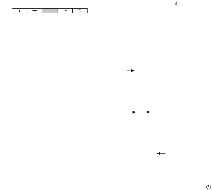
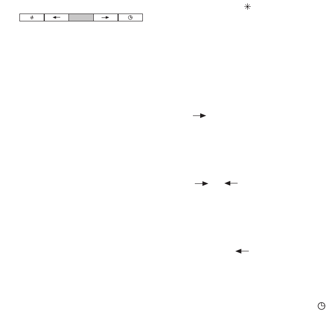
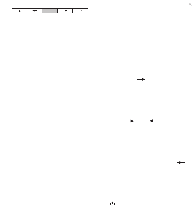
bediening . . . . . . . . . . . . . . . . . . . . . . . . . . . . . . . . 3
verlichting . . . . . . . . . . . . . . . . . . . . . . . . . . . . . . . . 3
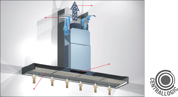
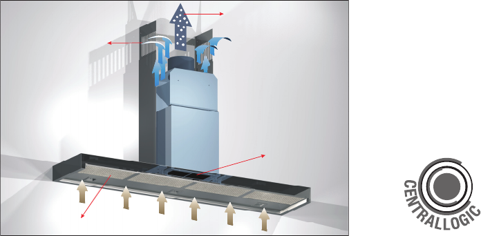
ventilator . . . . . . . . . . . . . . . . . . . . . . . . . . . . . . . . . 3
storingen . . . . . . . . . . . . . . . . . . . . . . . . . . . . . 4
hoe blijft het toestel mooi . . . . . . . . . . . . . 5 - 6
algemeen . . . . . . . . . . . . . . . . . . . . . . . . . . . . . . . . 5
buitenzijde . . . . . . . . . . . . . . . . . . . . . . . . . . . . . . . 5
metalen vetfilters . . . . . . . . . . . . . . . . . . . . . . . . . 5
koolstoffilter . . . . . . . . . . . . . . . . . . . . . . . . . . . . . . 6
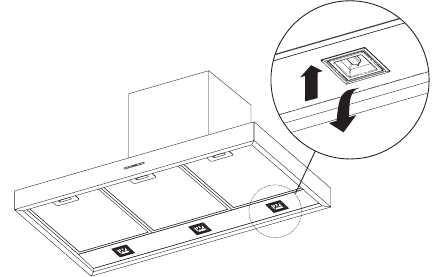
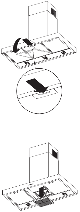
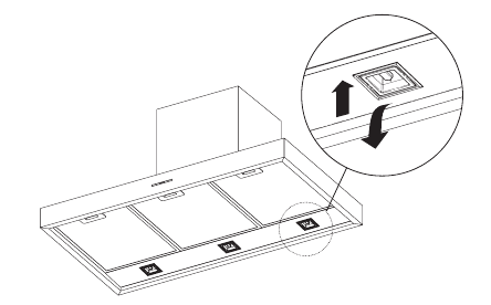
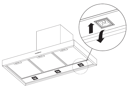
vetfilters verwijderen / plaatsen . . . . . . . . . . . . 6
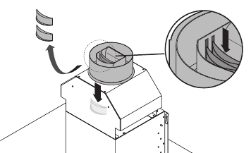
koolstoffilter verwijderen . . . . . . . . . . . . . . . . . . 6
installatie . . . . . . . . . . . . . . . . . . . . . . . . . . 7 - 8
opmerkingen vooraf . . . . . . . . . . . . . . . . . . . . . . . 7
elektrische aansluiting . . . . . . . . . . . . . . . . . . . . . 7
afvoer . . . . . . . . . . . . . . . . . . . . . . . . . . . . . . . . . . 8
instellen Volume regelklep . . . . . . . . . . . . . . . . . .8
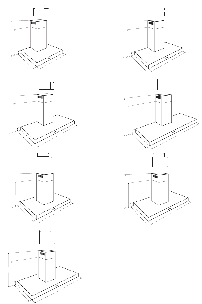
toestelmaten . . . . . . . . . . . . . . . . . . . . . . . . . . . . . 9
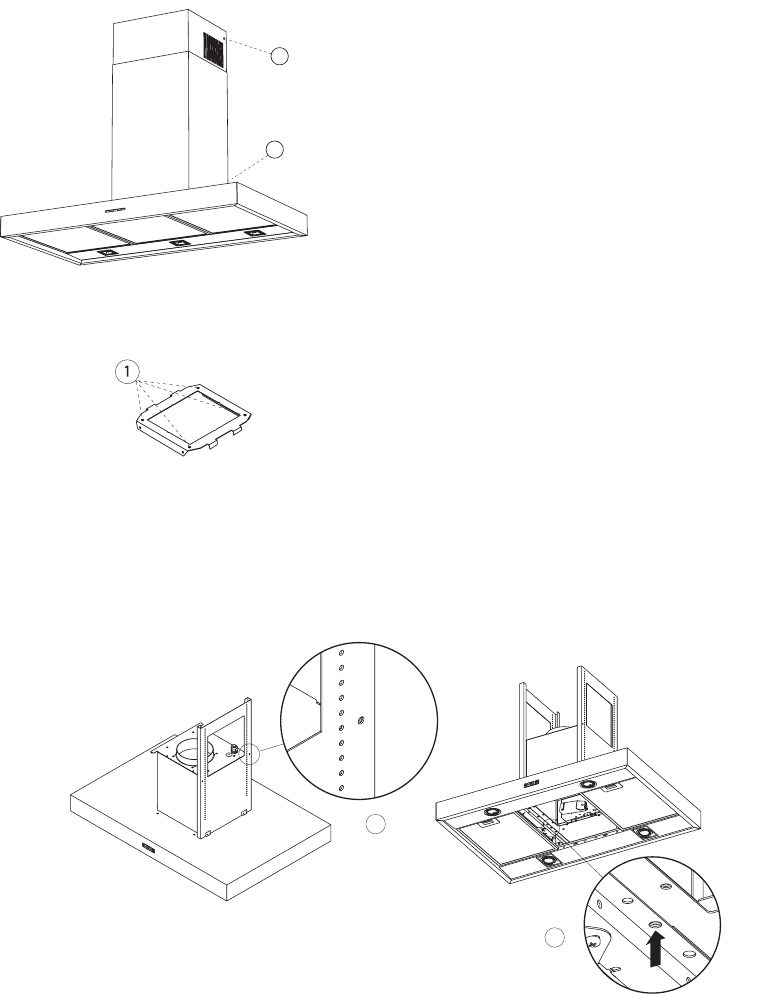
montage . . . . . . . . . . . . . . . . . . . . . . . . . . 10 -12
algemeen . . . . . . . . . . . . . . . . . . . . . . . . . . . . . . . 10
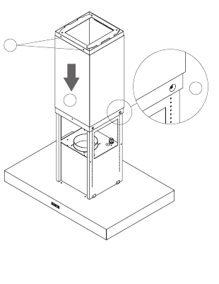
montage wandmodel . . . . . . . . . . . . . . . . . . . . . 10
montage eilandmodel . . . . . . . . . . . . . . . . . . . . . 11
technische gegevens . . . . . . . . . . . . . . . . . . . 12
milieuaspecten . . . . . . . . . . . . . . . . . . . . . . . 13