AS 625 KM / AS 585 KM
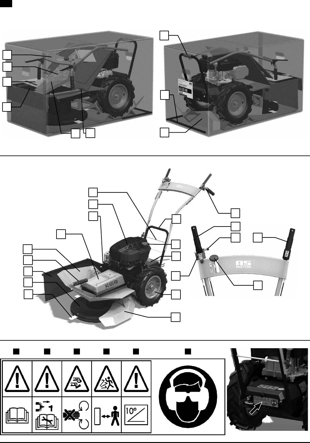
Cutting disk top cover . Drive cover Machine frame . Handle
( Front handle 1 Bolt ( Tank cap 1 Disk drive clutch lever
) Side cover with a holder , Engine ) Gearbox cover , Lock button
/ Cutting disk = Side cover screw / Strap with cables = Travel clutch lever
2 Blade (4 pcs) 7 Cutting disk bottom cover 2 Wheels (7 Gas lever
Table 5: Legend on Fig. 2
1.4 Operating Instructions
1.4.1 Machine Assembly
Gripping points for unpacking from the box (per
Fig. 1
): grab the cutting disk at the front or use hole under the gearbox cover , and the
machine frame tube in the rear (.
1.4.1.1 Machine Assembly Procedure
Assemble the machine per the following procedure:
(We recommend completing the assembly by two persons)
1. Per
Fig. 1
- take out both halves of the disk cover 2, bag ., bolt /, cover support =, both side cover components 1, and
bottom disk cover ,. Remove the cardboard insert between the handlebars and the engine from the box.
2. Grab the machine, using its gripping points at the front and in the back ( and remove it from the box.
3. Lift the handlebars ) per
Fig. 1
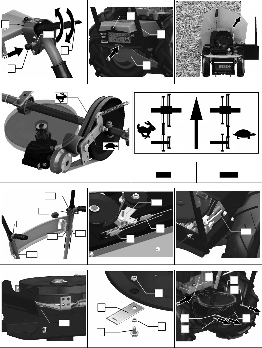
, turn them a attach per
Fig. 10
step G to the frame (select one of the 3 holes in the height-
adjusting handlebars and one of the two holes in the frame). Following G , pass the screw through, attach the flat washer, and
firmly tighten the handlebars with the wing nut . The bowden cables of the control levers must not be crossed - this would
reduce their service life! Remove the tightening straps from the bag and attach the bowden cables to the handlebars at the top
end of the handlebar tube bend. To fasten, 2 strapping tapes are sufficient. Cut the loose ends of the straps.
4. Following
Fig. 10
G), attach the bottom disk cover ( to the left side of the frame by means of 4 screws : and fasten it.
Tighten the screws.
5. Following
Fig. 10
G), fit the screw : into the hole in the right rear part of the frame, but do not tighten it. Insert the right
(bigger) part of the cover ) between the bottom plastic cover of the disk and machine frame, so the screws : and @ in the
frame fit into the three grooves in the cover marked with an arrow. Manually tighten the screw connection :. Do not tighten the
screw connection @ for the time being. Attach the right side of the cover by three screws : per G/. Manually tighten the
screw connection : per G/.
6. Following
Fig. 10
G2, insert a screw: into the rear part hole and slide the smaller left part of the cover towards the frame
from the machine’s left side and fasten it with two screws : per G.. Manually tighten the screws:. Connect both halves of
the cover together in the front section per G) by means of the two connections !. Tighten the screw connection !.
7. Following
Fig. 10
G1, fit the handle holder2 onto the left cover reinforcement and secure it with two screw connections!.
Attach the rubber handle component. to the fixed holder.
8. Tighten all the screw connections : and @ per G(, G), G/, G2 and G. !
9. Following
Fig. 10
G,, attach the rear (shorter) side cover to its shorter holder arm,, and then attach the side (longer) cover
to its longer holder arm1. Pull the strapping tapes through the cover holder holes and secure both covers1 and, against
sliding by tightening the tapes. Please shorten the loose ends of the tapes. Slide the shorter arm of the cover holder into the hole
in the frame. Tighten the fastening screw = per
Fig. 2
and make sure the side cover does not spontaneously fall.
1.4.2 Commissioning
$ (depending on different national regulations)!
A
17
'
1. Check the engine oil level or fill the engine with the specified type and amount of oil. Fill the tank with the prescribed quantity
and type of petrol.
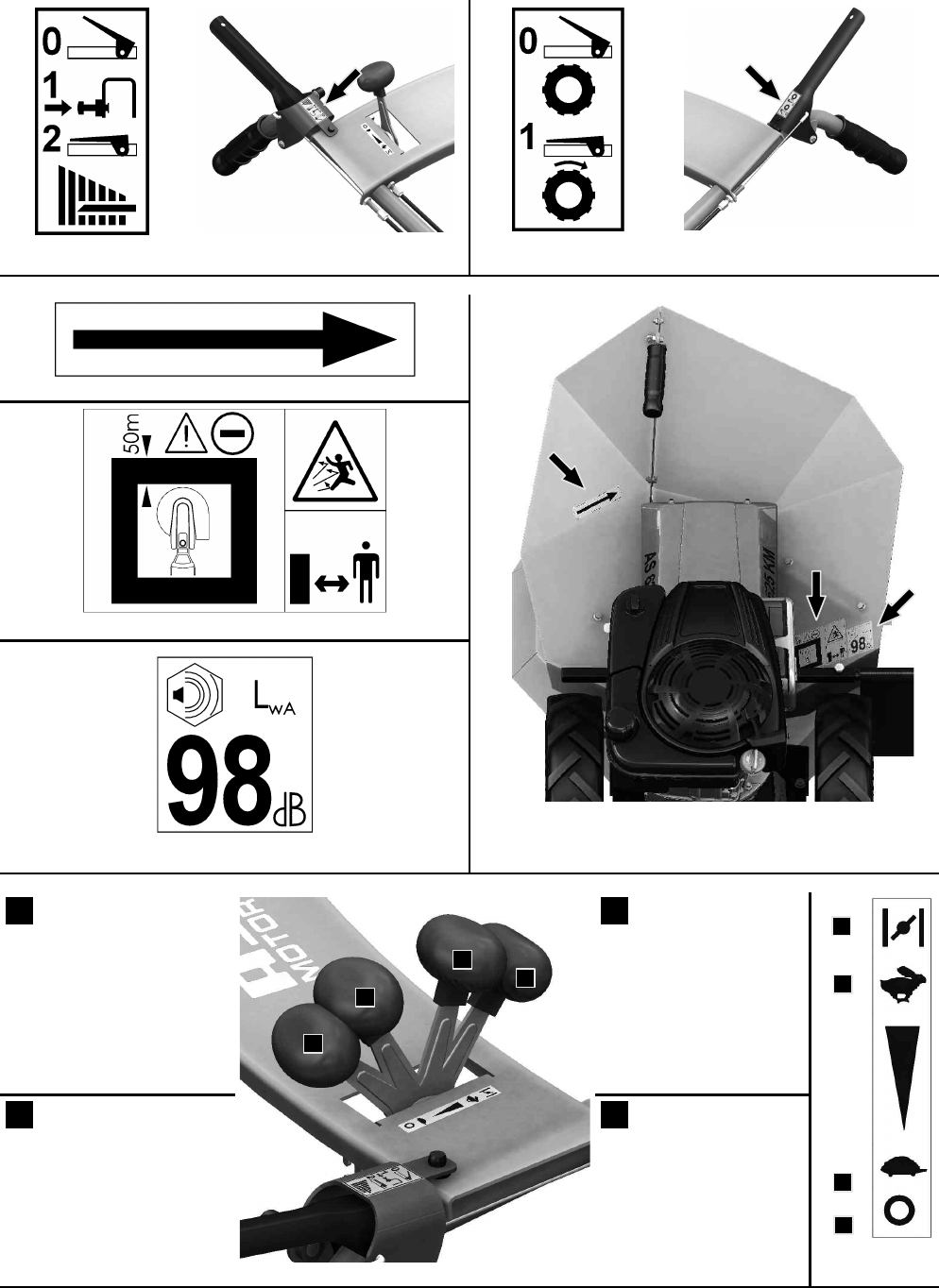
2. .(234 – Move the accelerator lever to its @-%3 or 4H
18
position. The accelerator lever positions are described in
Fig. 9
.
All four of the main positions described are locked by a simple, protruding system in the lever body.
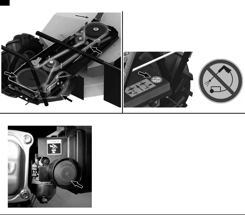
2,234 – Move the accelerator lever to its 4H position. When the engine is cold, press the PRIMER three times to inject
the fuel to the carburettor
19
-
Fig. 23
.
$$+'I$
AJ&4J'
3. Start the engine by pulling on the hand starter cord
20
.
4. .(234 – Let the new or cold engine run for about 30 seconds with the choke engaged (accelerator lever in the @-%3
position)
21
. After that, move the accelerator lever to the 4Hposition. Let the engine run in this position for about 30 seconds.
1
The original operating instructions and their Czech translation are attached to the machine.
,
The 4H position is used in the case of an automatic choke engine. For more information, see the engine operating instructions, please.
=
The engine startup instructions are described in detail in the engine operating instructions.
(7
The engine startup instructions are described in detail in the engine operating instructions.
(
In the case of an engine with automatic choke, let the engine run for about 30 seconds with the accelerator lever in the 4H position.
9